FEDERAL PIONEER H-2 Maintenance manual

V
.
CONTENTS
GENERAL
DESCRIPTION
General
Basic
Breaker
Types
Breaker
Description
RECEIVING
,
HANDLING
AND
STORAGE
PAGE
2
2
2
4
BREAKER
OPERATION
Drawout
Mounted
Breakers
.
Drawout
Racking
Mechanism
Fixed
Mounted
Breakers
.
.
.
Power
Terminal
Connections
Secondary
Control
Circuits
.
Pre
Service
Inspection
Manual
Closing
Electrical
Closing
4
4
4
4
4
4
6
6
BREAKER
MAINTENANCE
Removing
the
Faceplate
Lubrication
Close
Latch
Adjustment
Mechanism
Latching
and
Trip
Shaft
Adjustment
.
.
Spring
Discharge
Interlock
Shunt
Trip
UnderVoltageTripTypes
A
&
B
Shunt
Close
Closing
Spring
Charging
Motor
Motor
Closing
Spring
Limit
Switch
Latch
Check
Switch
Contact
Maintenance
Main
Power
Contacts
Contact
Differential
Main
Moving
Contact
Deflection
Arcing
Contacts
Slow
Close
Device
Arc
Chutes
Arc
Chute
Hood
Overload
Protection
Fuse
Mounting
Anti
-
Single
Phase
Device
and
Blown
Fuse
Indicator
Secondary
Control
Contacts
Auxiliary
Switch
Door
Interlock
Key
Interlocks
Spare
Parts
6
>
6
8
10
11
11
12
13
14
14
14
15
15
15
16
16
16
19
19
19
19
19
20
20
20
20
21
Page
1
Courtesy of store.ips.us
This
manual
applies
to
breakers
commencing
Serial
number
BH
.
For
breakers
with
serial
numbers
TH
consult
Instruction
Manual
C
-
3
-
211
-
1
dated
March
1976
.
For
breakers
with
serial
numbers
T
consult
Instruction
Manual
C
-
3
-
414
dated
August
1966
.
C
Before
placing
in
service
read
this
instruction
man
-
ual
completely
and
perform
the
pre
-
service
inspec
-
tion
(
see
page
4
)
.
L
Courtesy of store.ips.us
GENERAL
Type
H
-
2
&
HL
-
2
power
Air
Circuit
Breakers
are
suitable
for
controlling
and
protecting
low
voltage
power
circuits
up
to
250
volts
dc
and
600
volts
ac
.
They
are
a
means
of
safely
switching
loads
and
automatically
clearing
circuits
when
abnormal
con
-
ditions
occur
such
as
undervoltage
,
sustained
overloads
,
and
short
circuits
.
The
proper
INSTALLATION
,
MAINTENANCE
and
OPERATION
of
these
breakers
is
a
prime
safety
consideration
for
the
protection
of
personnel
and
equipment
.
Reference
to
this
manual
and
adherence
to
its
recommendations
will
enhance
the
performance
of
these
breakers
under
all
conditions
.
This
manual
does
not
purport
to
cover
all
details
or
variations
of
equipment
nor
to
provide
for
every
possible
contingency
to
be
met
in
connection
with
receiving
,
storage
,
installation
,
maintenance
or
operation
.
Should
further
information
be
required
or
particular
problems
arise
which
are
not
covered
suf
-
ficiently
,
please
refer
to
Federal
Pioneer
Limited
.
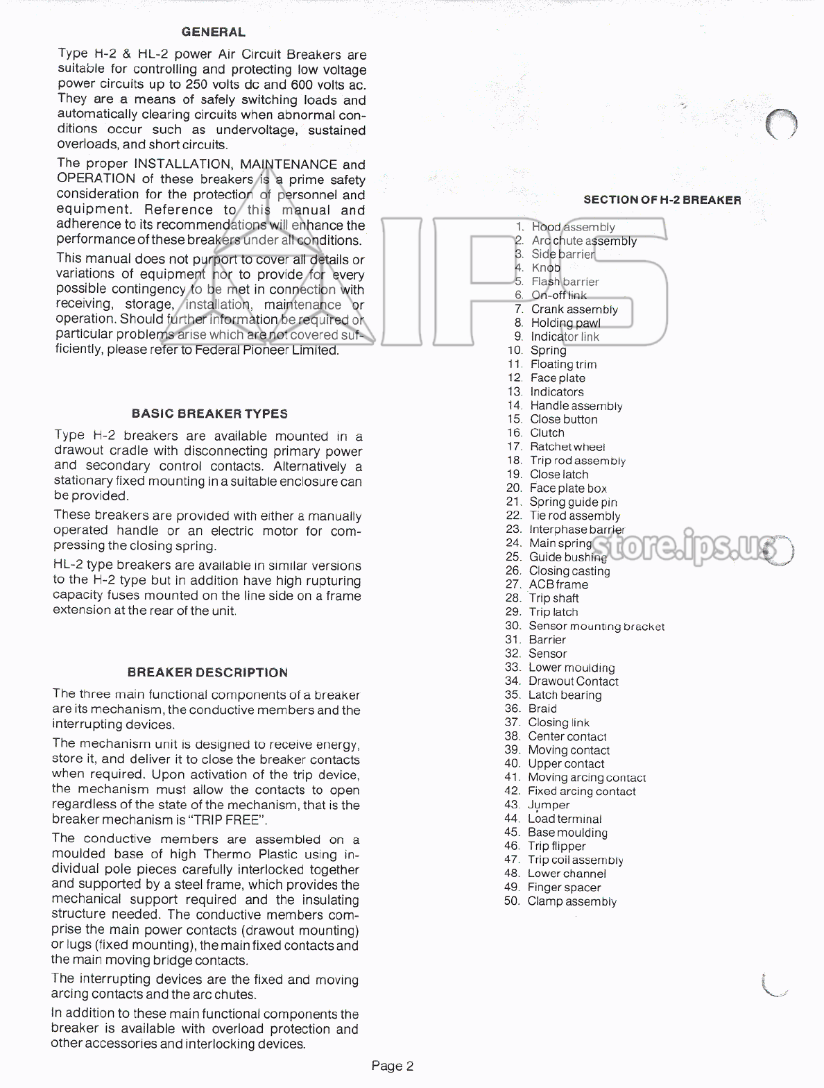
SECTION
OF
H
-
2
BREAKER
1
.
Hood
assembly
2
.
Arc
chute
assembly
3
.
Side
barrier
4
.
Knob
5
.
Flash
barrier
6
.
On
-
off
link
7
.
Crank
assembly
8
.
Holding
pawl
9
.
Indicator
link
10
.
Spring
11
.
Floating
trim
12
.
Faceplate
13
.
Indicators
14
.
Handle
assembly
15
.
Close
button
16
.
Clutch
17
.
Ratchet
wheel
18
.
Trip
rod
assembly
19
.
Close
latch
20
.
Face
plate
box
21
.
Spring
guide
pin
22
.
Tie
rod
assembly
23
.
Interphase
barrier
24
.
Mainspring
25
.
Guide
bushing
26
.
Closing
casting
27
.
ACB
frame
28
.
Trip
shaft
29
.
Trip
latch
30
.
Sensor
mounting
bracket
31
.
Barrier
32
.
Sensor
33
.
Lower
moulding
34
.
Drawout
Contact
35
.
Latch
bearing
36
.
Braid
37
.
Closing
link
38
.
Center
contact
39
.
Moving
contact
40
.
Upper
contact
41
.
Moving
arcing
contact
42
.
Fixed
arcing
contact
43
.
Jumper
44
.
Load
terminal
45
.
Base
moulding
46
.
Trip
flipper
47
.
Trip
coil
assembly
48
.
Lower
channel
49
.
Finger
spacer
50
.
Clamp
assembly
BASIC
BREAKER
TYPES
Type
H
-
2
breakers
are
available
mounted
in
a
drawout
cradle
with
disconnecting
primary
power
and
secondary
control
contacts
.
Alternatively
a
stationary
fixed
mounting
in
a
suitable
enclosure
can
be
provided
.
These
breakers
are
provided
with
either
a
manually
operated
handle
or
an
electric
motor
for
com
-
pressing
the
closing
spring
.
HL
-
2
type
breakers
are
available
in
similar
versions
to
the
H
-
2
type
but
in
addition
have
high
rupturing
capacity
fuses
mounted
on
the
line
side
on
a
frame
extension
at
the
rear
of
the
unit
.
BREAKER
DESCRIPTION
The
three
main
functional
components
of
a
breaker
are
its
mechanism
,
the
conductive
members
and
the
interrupting
devices
.
The
mechanism
unit
is
designed
to
receive
energy
,
store
it
,
and
deliver
it
to
close
the
breaker
contacts
when
required
.
Upon
activation
of
the
trip
device
,
the
mechanism
must
allow
the
contacts
to
open
regardless
of
the
state
of
the
mechanism
,
that
is
the
breaker
mechanism
is
“
TRIP
FREE
”
.
The
conductive
members
are
assembled
on
a
moulded
base
of
high
Thermo
Plastic
using
in
-
dividual
pole
pieces
carefully
interlocked
together
and
supported
by
a
steel
frame
,
which
provides
the
mechanical
support
required
and
the
insulating
structure
needed
.
The
conductive
members
com
-
prise
the
main
power
contacts
(
drawout
mounting
)
or
lugs
(
fixed
mounting
)
,
the
main
fixed
contacts
and
the
main
moving
bridge
contacts
.
The
interrupting
devices
are
the
fixed
and
moving
arcing
contacts
and
the
arc
chutes
.
In
addition
to
these
main
functional
components
the
breaker
is
available
with
overload
protection
and
other
accessories
and
interlocking
devices
.
Page
2
Courtesy of store.ips.us

RECEIVING
,
HANDLING
AND
STORAGE
Receiving
Immediately
upon
receipt
of
the
breaker
an
ex
-
amination
should
be
made
for
damage
sustained
in
transit
.
If
damage
has
occurred
or
there
is
evidence
of
rough
handling
a
claim
should
be
filed
im
-
mediately
with
the
transportation
company
and
Federal
Pioneer
Limited
should
be
notified
.
Check
all
parts
against
the
packing
list
to
make
sure
all
the
correct
items
have
been
received
.
Except
for
the
mounting
the
following
instructions
for
fixed
mounted
breakers
equally
apply
to
drawout
mounted
breakers
.
FIXED
MOUNTED
BREAKERS
H
-
2
and
HL
-
2
circuit
breakers
should
be
mounted
in
sheet
steel
enclosures
in
accordance
with
recommended
dimensions
.
The
mounting
support
should
be
a
rigid
structure
able
to
withstand
the
im
-
pact
caused
by
the
switching
operations
,
without
any
deflection
of
the
frame
which
may
cause
distor
-
tion
and
undue
vibration
of
the
mechanism
.
•
x
-
POWER
TERMINAL
CONNECTIONS
The
H
-
2
and
HL
-
2
terminals
are
silver
plated
for
maximum
joint
efficiency
and
cable
connectors
must
be
clean
and
free
from
dents
or
burrs
,
and
bolted
securely
to
the
terminals
.
Poor
joints
lead
to
over
-
heating
and
subsequent
contact
deterioration
,
and
an
eventual
failure
.
Cables
or
bus
connections
should
be
properly
supported
so
as
not
to
transfer
any
unnecessary
mechanical
or
short
circuit
stress
to
the
terminals
.
Any
strain
which
may
have
no
ap
-
parent
effect
initially
,
may
,
after
prolonged
periods
of
vibration
and
shock
from
normal
operation
,
cause
poor
contact
alignment
.
Meter
shunts
,
resistors
,
and
similar
devices
which
operate
at
relatively
high
temperature
should
be
mounted
away
from
the
circuit
breaker
so
they
do
not
contribute
to
the
heating
of
the
unit
.
Handling
and
Storage
Lift
the
breaker
by
the
steel
channels
at
the
front
and
back
.
Do
not
lift
by
the
connecting
terminals
or
the
asbestos
hoods
and
arc
chutes
,
or
by
the
operating
handle
.
Check
the
unit
thoroughly
to
see
that
no
parts
were
damaged
or
forced
out
of
alignment
dur
-
ing
shipment
.
If
replacement
parts
are
required
,
the
manufacturer
should
be
notified
promptly
.
The
breaker
should
be
installed
in
a
clean
dry
ventilated
area
,
which
is
free
from
atmospheric
contaminants
.
Each
circuit
breaker
should
be
stored
in
its
shipping
crate
in
an
upright
position
in
a
clean
dry
area
.
Should
the
unit
get
wet
,
it
must
be
thoroughly
dried
out
using
forced
warm
air
over
an
extended
period
until
“
infinite
"
readings
are
obtained
using
a
600
volt
megger
.
BREAKER
OPERATION
SECONDARY
CONTROL
CIRCUITS
Control
circuit
wiring
,
where
applicable
,
should
be
made
in
strict
accordance
with
detailed
wiring
diagrams
.
Wiring
connections
,
which
are
made
to
terminal
blocks
should
be
run
in
a
supported
and
protected
manner
,
so
control
wiring
cannot
come
into
contact
with
the
primary
connections
.
DRAWOUT
MOUNTED
BREAKERS
Switchgear
assemblies
for
drawout
mounted
breakers
are
provided
with
supporting
rails
,
main
power
contacts
and
secondary
contacts
to
mate
with
those
on
the
breakers
when
it
is
racked
into
position
.
Drawout
Racking
Mechanism
An
interlock
is
provided
which
will
ensure
that
the
unit
is
open
and
the
main
spring
is
discharged
when
it
is
either
engaging
or
disengaging
the
main
dis
-
connecting
contacts
.
A
block
is
provided
on
the
racking
mechanism
which
operates
in
conjunction
with
the
gate
interlock
lever
over
the
racking
open
-
ing
.
Before
withdrawing
electrically
operated
breakers
,
turn
off
the
motor
isolating
switch
on
the
faceplate
.
To
withdraw
the
unit
,
move
the
gate
over
the
crank
opening
down
so
as
to
expose
the
socket
end
of
the
drawout
racking
shaft
.
This
action
will
first
open
the
unit
if
it
is
closed
and
then
discharge
the
main
spring
if
it
is
charged
.
The
racking
handle
may
now
be
inserted
in
the
racking
shaft
socket
and
by
counter
-
clockwise
rotation
the
unit
will
move
out
-
ward
.
At
the
“
test
”
position
the
main
contacts
are
withdrawn
but
the
auxiliary
contacts
remain
engag
-
ed
in
the
test
position
.
Further
turns
of
the
racking
handle
will
move
the
unit
to
the
“
disconnected
”
position
and
it
is
then
free
to
be
pulled
manually
forward
to
the
end
of
the
tracks
.
Two
lifting
lugs
are
provided
on
each
side
of
the
unit
so
that
it
can
be
lifted
clear
of
the
tracks
.
PRE
-
SERVICE
INSPECTION
Read
this
instruction
manual
completely
and
inspect
and
check
the
unit
in
accordance
with
this
manual
.
The
following
items
should
be
specifically
checked
.
1
.
Make
a
visual
inspection
after
installation
to
en
-
sure
that
no
parts
have
been
damaged
or
forced
out
of
alignment
.
2
.
Check
the
door
interlock
lever
for
freedom
of
movement
,
when
supplied
.
(
Fig
.
25
)
.
3
.
Check
the
main
and
drawout
contacts
to
see
that
they
are
clean
and
free
from
foreign
material
.
4
.
Check
all
the
control
wiring
to
ensure
that
it
has
not
been
damaged
or
moved
during
the
installation
.
5
.
Check
the
single
phase
protection
(
when
supplied
)
by
manually
raising
each
tripping
plunger
in
turn
on
the
three
tripping
coils
,
Fig
.
24
.
If
the
unit
is
closed
,
it
should
trip
and
the
correct
indicator
should
show
on
the
faceplate
.
(
Fig
.
2
)
.
6
.
Close
and
open
the
unit
several
times
to
ensure
correct
operation
.
Interlocks
should
be
defeated
or
be
in
normal
release
position
.
If
an
under
voltage
trip
unit
is
attached
hold
it
up
manually
,
so
the
spring
Page
4
Courtesy of store.ips.us
closing
mechanism
will
pick
up
the
contacts
,
and
thus
avoid
discharging
the
mechanism
without
its
normal
contact
spring
load
.
7
.
Manually
activate
the
tripping
devices
to
es
-
tablish
that
they
are
operable
.
These
devices
include
manual
trip
Fig
.
2
,
shunt
trip
Figs
.
11
,
12
and
under
-
voltage
trip
Figs
.
11
,
13
.
8
.
Check
all
cable
connections
to
ensure
that
they
are
tight
.
9
.
The
electrical
operation
of
drawout
breakers
should
be
checked
in
the
‘
test
’
position
.
V
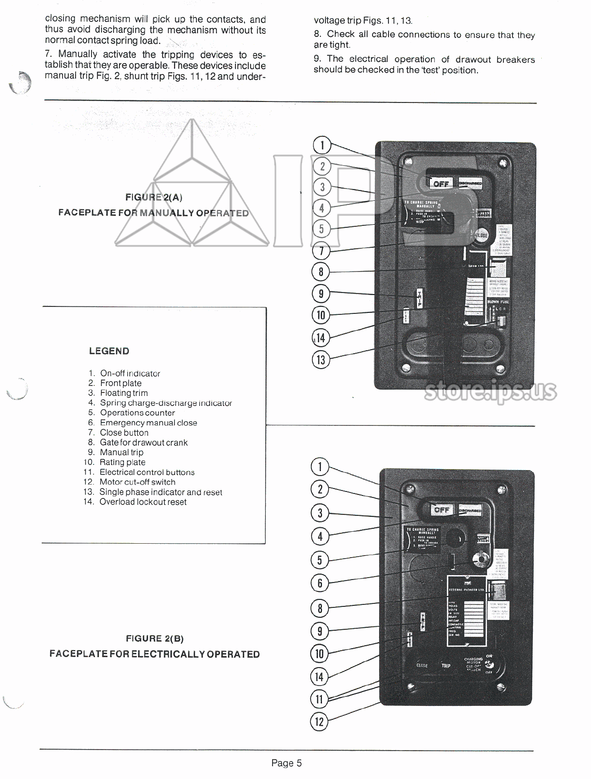
FIGURE
2
(
A
)
FACEPLATE
FOR
MANUALLY
OPERATED
©
10
14
LEGEND
13
1
.
On
-
off
indicator
2
.
Front
plate
3
.
Floating
trim
4
.
Spring
charge
-
discharge
indicator
5
.
Operations
counter
6
.
Emergency
manual
close
7
.
Close
button
8
.
Gate
for
drawout
crank
9
.
Manual
trip
10
.
Rating
plate
11
.
Electrical
control
buttons
12
.
Motor
cut
-
off
switch
13
.
Single
phase
indicator
and
reset
14
.
Overload
lockout
reset
FIGURE
2
(
B
)
FACEPLATE
FOR
ELECTRICALLY
OPERATED
10
14
11
12
Page
5
Courtesy of store.ips.us
Manual
Closing
The
closing
mechanism
compresses
a
main
spring
which
is
held
compressed
until
released
.
The
handle
is
rotated
counter
-
clockwise
to
the
vertical
position
and
pushed
in
to
engage
the
clutch
.
Rotating
the
handle
180
°
clockwise
fully
charges
the
spring
and
as
the
internal
crank
passes
through
top
-
dead
-
centre
,
rotation
is
stopped
,
and
held
by
the
close
release
latch
.
Operation
of
this
latch
by
means
of
the
close
push
button
Fig
.
2
in
the
faceplate
releases
the
spring
energy
to
close
the
breaker
.
A
multi
-
tooth
ratchet
wheel
prevents
recoil
and
permits
the
spring
charging
to
be
performed
in
several
short
strokes
if
desired
.
On
frame
sizes
1600
amperes
and
above
,
the
handle
is
a
pull
-
out
extension
type
for
ease
of
operation
.
breakers
were
still
operational
.
In
service
it
is
possi
-
ble
to
encounter
dusk
,
corrosive
atmospheres
and
other
adverse
conditions
which
may
impair
proper
operation
.
Therefore
we
consider
it
prudent
to
lubricate
and
clean
breakers
periodically
.
ANSI
standards
recommend
lubrication
and
servicing
to
be
carried
out
at
the
following
periods
.
In
frame
sizes
up
to
and
including
2000
amps
,
this
interval
is
500
operations
,
and
in
sizes
3000
amps
and
above
,
250
operations
.
The
following
points
should
receive
attention
:
-
Electrical
Closing
On
all
electrically
operated
units
the
motor
charges
the
spring
unit
the
close
release
latch
engages
.
The
close
latch
is
operated
by
a
solenoid
energized
from
the
push
button
in
the
faceplate
,
Fig
.
2
or
by
a
remote
button
.
The
closing
stroke
then
follows
in
a
similar
manner
to
that
of
the
manual
type
described
above
.
A
removable
handle
is
provided
to
permit
manual
charging
of
the
spring
.
A
mechanical
close
button
similar
to
that
on
the
manually
operated
unit
is
not
included
.
Emergency
operation
of
the
close
release
latch
is
accomplished
by
insertion
of
a
pin
through
a
small
aperture
in
the
faceplate
,
Fig
.
2
.
A
suitable
pin
is
provided
in
the
upper
end
of
the
manual
charging
handle
.
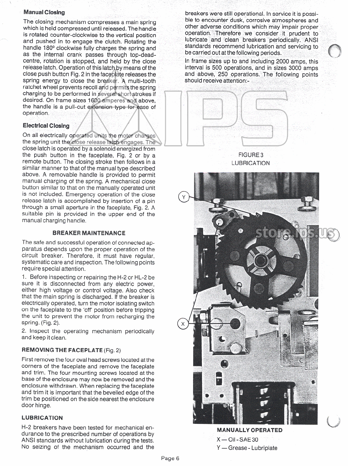
FIGURE
3
LUBRICATION
Y
BREAKER
MAINTENANCE
The
safe
and
successful
operation
of
connected
ap
-
paratus
depends
upon
the
proper
operation
of
the
circuit
breaker
.
Therefore
,
it
must
have
regular
,
systematic
care
and
inspection
.
The
following
points
require
special
attention
.
1
.
Before
inspecting
or
repairing
the
H
-
2
or
HL
-
2
be
sure
it
is
disconnected
from
any
electric
power
,
either
high
voltage
or
control
voltage
.
Also
check
that
the
main
spring
is
discharged
.
If
the
breaker
is
electrically
operated
,
turn
the
motor
isolating
switch
on
the
faceplate
to
the
‘
off
’
position
before
tripping
the
unit
to
prevent
the
motor
from
recharging
the
spring
.
(
Fig
.
2
)
.
2
.
Inspect
the
operating
mechanism
periodically
and
keep
it
clean
.
X
REMOVING
THE
FACEPLATE
(
Fig
.
2
)
First
remove
the
four
oval
head
screws
located
at
the
corners
of
the
faceplate
and
remove
the
faceplate
and
trim
.
The
four
mounting
screws
located
at
the
base
of
the
enclosure
may
now
be
removed
and
the
enclosure
withdrawn
.
When
replacing
the
faceplate
and
trim
it
is
important
that
the
bevelled
edge
of
the
trim
be
positioned
on
the
side
nearest
the
enclosure
door
hinge
.
LUBRICATION
H
-
2
breakers
have
been
tested
for
mechanical
en
-
durance
to
the
prescribed
number
of
operations
by
ANSI
standards
without
lubrication
during
the
tests
.
No
seizing
of
the
mechanism
occurred
and
the
MANUALLY
OPERATED
X
—
OM
-
SAE
30
Y
—
Grease
-
Lubriplate
Page
6
Courtesy of store.ips.us

MANUALLY
OPERATED
MECHANISM
(
Ref
.
Fig
.
3
)
.
Oil
-
SAE
30
1
.
All
linkage
pivots
within
the
mechanism
compart
-
ment
.
2
.
All
closing
shaft
bearings
.
3
.
Holding
pawl
pivot
(
located
within
the
faceplate
enclosure
-
upper
left
hand
corner
)
.
4
.
Close
latch
pivot
(
located
below
the
main
ratchet
wheel
)
.
Grease
-
Lubriplate
Lo
-
Temp
.
1
.
Spring
guide
pin
(
located
at
the
lower
end
of
the
closing
spring
)
.
2
.
Ratchet
wheel
teeth
.
closing
spring
)
.
2
.
Ratchet
wheel
teeth
.
3
.
Front
face
of
the
ratchet
wheel
.
4
.
Oscillating
lever
-
right
hand
end
(
at
the
motor
drive
cam
)
.
5
.
Driving
pawl
pivot
and
springs
(
located
on
left
hand
end
of
the
closing
spring
)
.
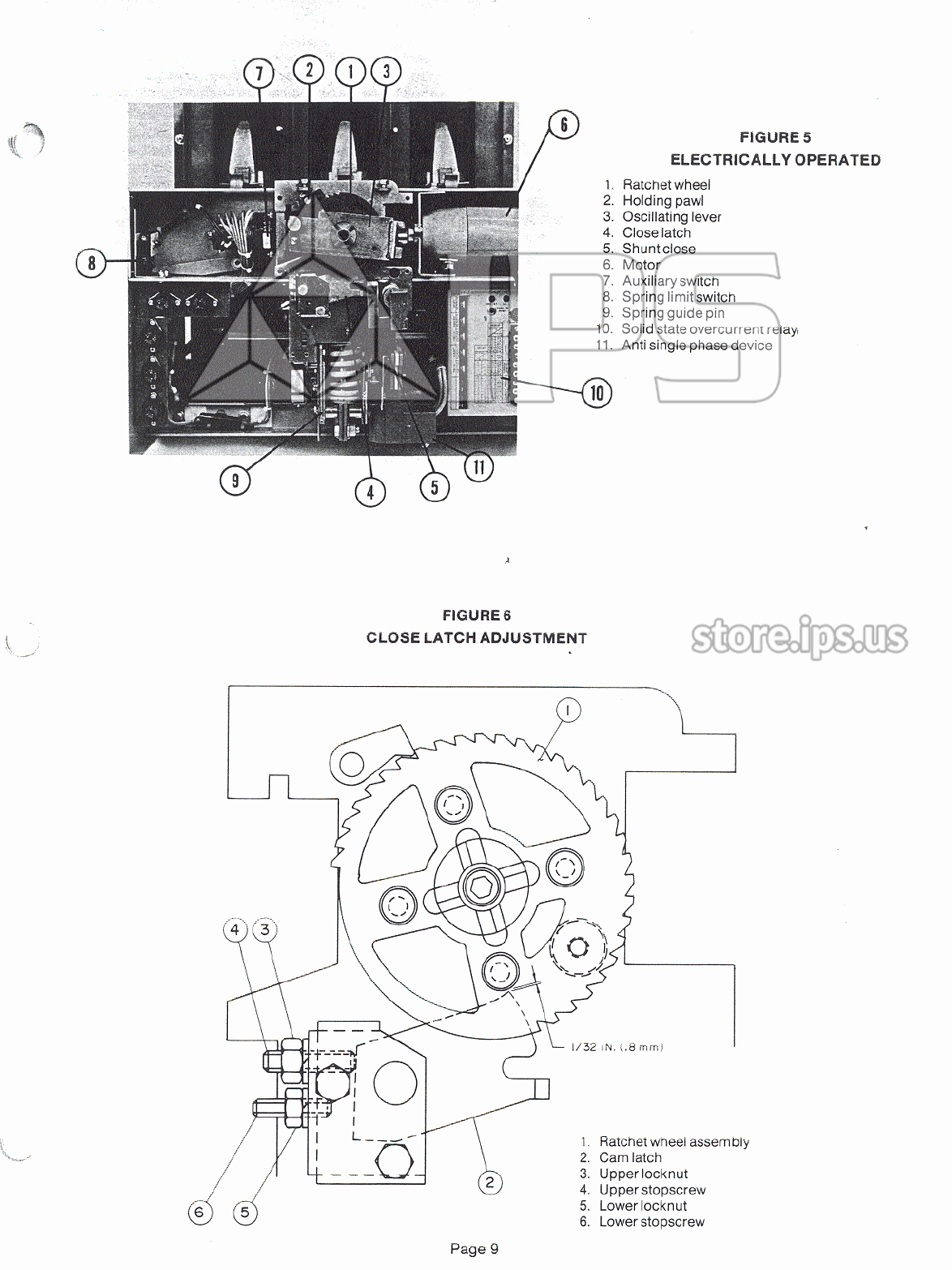
CLOSE
LATCH
ADJUSTMENT
(
Fig
.
6
)
The
function
of
the
close
latch
is
to
arrest
or
hold
the
ratchet
wheel
at
a
point
12
degrees
past
top
-
dead
-
centre
,
with
the
spring
fully
charged
in
readiness
to
close
.
The
closing
stroke
is
initiated
by
release
of
the
latch
,
either
manually
by
means
of
the
mechanical
push
button
in
the
faceplate
or
electrically
by
means
of
the
close
solenoid
.
Insufficient
engagement
of
the
latch
may
allow
the
closing
stroke
to
occur
at
com
-
pletion
of
the
charging
of
the
spring
.
Referring
to
Figure
6
,
the
adjustment
procedure
is
as
follows
.
The
ratchet
wheel
assembly
(
Item
1
)
is
made
up
of
two
plates
riveted
together
.
The
two
plates
are
held
apart
by
spacers
located
between
the
plates
on
the
four
rivets
.
Rotate
the
ratchet
wheel
until
one
of
the
spacers
on
a
rivet
is
directly
above
the
nose
of
the
cam
latch
(
Item
2
)
.
Loosen
locknut
(
Item
3
)
.
Turning
the
stop
screw
(
Item
4
)
counter
-
clockwise
adjusts
the
cam
latch
up
.
Adjust
the
cam
latch
height
until
there
is
approximately
1
/
32
inch
(
.
8
mm
)
clearance
between
the
spacer
and
the
nose
of
the
cam
latch
.
Tighten
the
locknut
securely
.
ELECTRICALLY
OPERATED
MECHANISM
(
Ref
.
Fig
.
3
)
.
Oil
-
SAE
30
1
.
All
linkage
pivots
within
the
mechanism
compart
-
ment
.
2
.
All
closing
shaft
bearings
.
3
.
Holding
pawl
pivot
(
located
within
the
faceplate
enclosure
-
upper
left
hand
corner
)
.
4
.
Motor
limit
switch
lever
pivot
(
located
within
the
front
channel
-
left
hand
corner
)
.
5
.
Close
latch
pivot
(
located
below
the
mam
ratchet
wheel
)
.
Grease
-
Lubriplate
Lo
-
Temp
.
1
.
Spring
guide
pin
(
located
at
the
lower
end
of
the
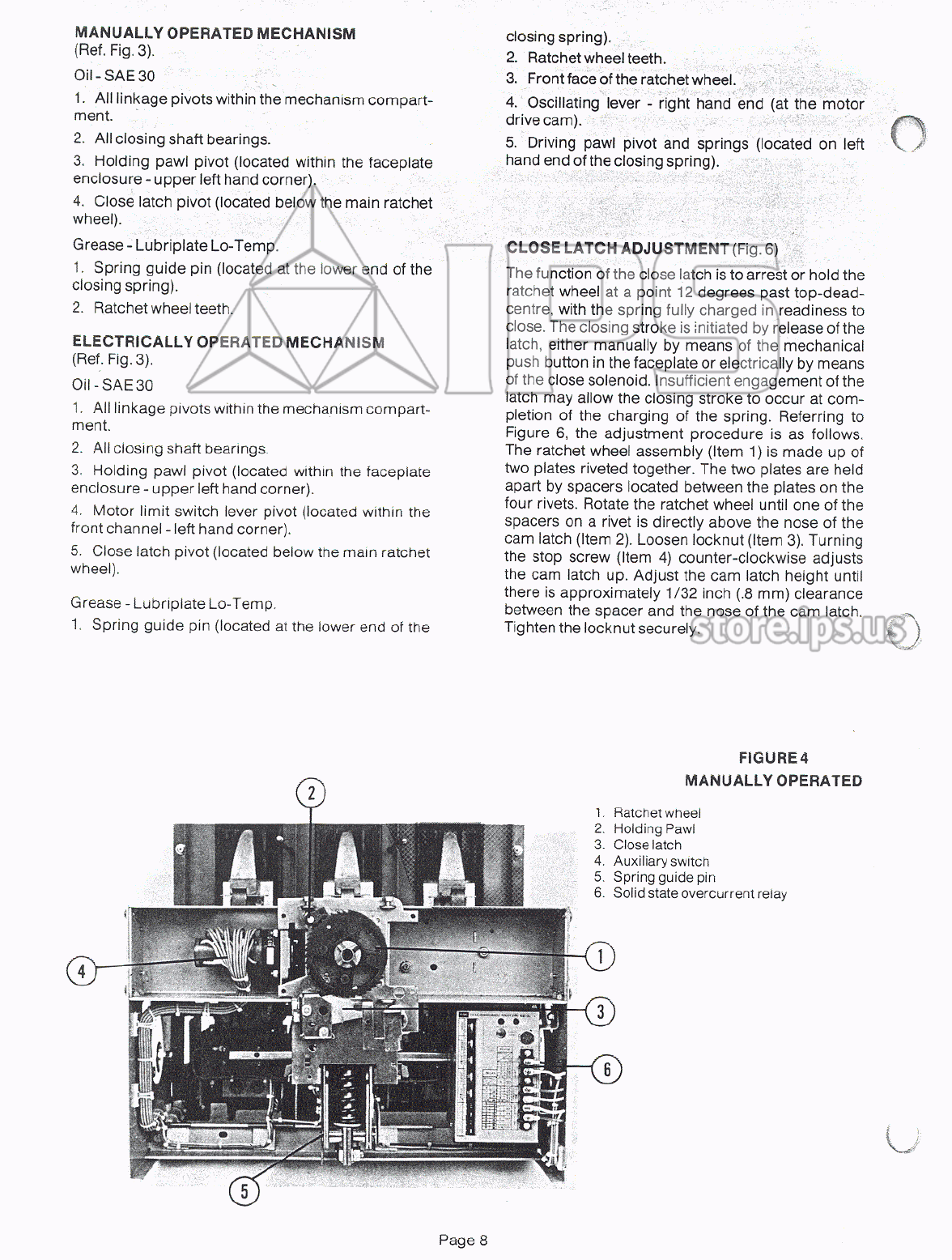
FIGURE
4
MANUALLY
OPERATED
2
1
.
Ratchet
wheel
2
.
Holding
Pawl
3
.
Close
latch
4
.
Auxiliary
switcn
5
.
Spring
guide
pin
6
.
Solid
state
overcurrent
relay
Courtesy of store.ips.us
FIGURES
ELECTRICALLY
OPERATED
1
.
Ratchet
wheel
2
.
Holding
pawl
3
.
Oscillating
lever
4
.
Close
latch
5
.
Shuntclose
6
.
Motor
7
.
Auxiliary
switch
8
.
Spring
limit
switch
9
.
Spring
guide
pin
10
.
Solid
state
overcurrent
relay
.
11
.
Anti
single
phase
device
10
FIGURE
6
CLOSE
LATCH
ADJUSTMENT
k
1
/
32
iN
.
l
,
8
mm
)
1
.
Ratchet
wheel
assembly
2
.
Cam
latch
3
.
Upper
locknut
4
.
Upper
stopscrew
5
.
Lower
locknut
6
.
Lower
stopscrew
£
Courtesy of store.ips.us
•
r
*
>
MECHANISM
LATCHING
AND
TRIP
SHAFT
ADJUSTMENT
Misadjustment
of
latching
results
in
failure
to
close
,
but
it
does
not
prevent
the
closing
spring
from
being
compressed
and
discharged
for
closure
.
There
are
3
possible
causes
of
improper
latching
:
A
)
On
units
equipped
with
an
overload
lockout
or
single
phase
device
,
failure
to
manually
reset
the
device
after
it
has
operated
,
will
prevent
latching
and
the
discharge
of
the
closing
spring
will
not
move
the
main
contacts
.
B
)
Misadjustment
of
the
main
linkage
(
which
governs
travel
of
the
latch
roller
)
will
prevent
latching
with
the
same
result
as
above
.
C
)
Insufficient
overlap
of
the
latch
roller
with
the
trip
cam
secured
to
the
trip
shaft
.
This
condition
will
cause
the
moving
contacts
to
pick
up
slightly
and
drop
back
to
fully
open
position
when
the
closing
spring
is
discharged
.
To
correct
A
-
push
manual
reset
lever
.
(
Fig
.
2
)
To
correct
B
-
Linkage
adjustment
must
be
made
(
Ref
.
Fig
.
7
)
.
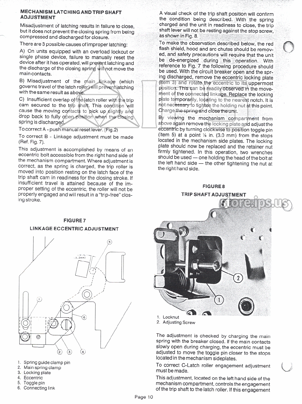
This
adjustment
is
accomplished
by
means
of
an
eccentric
bolt
accessible
from
the
right
hand
side
of
the
mechanism
compartment
.
Where
adjustment
is
correct
,
as
the
spring
is
charged
,
the
trip
roller
is
moved
into
position
resting
on
the
latch
face
of
the
trip
shaft
cam
in
readiness
for
the
closing
stroke
.
If
insufficient
travel
is
attained
because
of
the
im
-
proper
setting
of
the
eccentric
,
the
roller
will
not
be
properly
engaged
and
will
result
in
a
“
trip
-
free
"
clos
-
ing
stroke
.
A
visual
check
of
the
trip
shaft
position
will
confirm
the
condition
being
described
.
With
the
spring
charged
and
the
unit
in
readiness
to
close
,
the
trip
shaft
lever
will
not
be
resting
against
the
stop
screw
,
as
shown
in
Fig
.
8
.
To
make
the
observation
described
below
,
the
red
flash
shield
,
hood
and
arc
chutes
should
be
remov
-
ed
,
and
safety
precautions
will
require
that
the
unit
be
de
-
energized
during
this
operation
.
With
reference
to
Fig
.
7
the
following
procedure
should
be
used
.
With
the
circuit
breaker
open
and
the
spr
-
ing
discharged
,
remove
the
eccentric
locking
plate
(
Item
3
)
and
rotate
the
eccentric
to
its
uppermost
position
.
This
can
be
readily
observed
in
the
move
-
ment
of
the
connected
linkage
.
Replace
the
locking
plate
temporarily
,
locating
to
the
nearest
notch
.
It
is
not
necessary
to
tighten
the
holding
nut
at
this
point
.
Charge
the
spring
and
close
the
unit
.
By
viewing
the
mechanism
compartment
from
above
again
remove
the
locking
plate
and
adjust
the
eccentric
by
turning
clockwise
to
position
toggle
pin
(
Item
5
)
at
a
point
Vi
in
.
(
3.0
mm
)
from
the
stops
located
in
the
mechanism
side
plates
.
The
locking
plate
should
now
be
replaced
and
the
retainer
nut
firmly
tightened
.
In
this
operation
,
two
wrenches
should
be
used
—
one
holding
the
head
of
the
bolt
at
the
left
hand
side
—
the
other
tightening
the
nut
at
the
right
hand
side
.
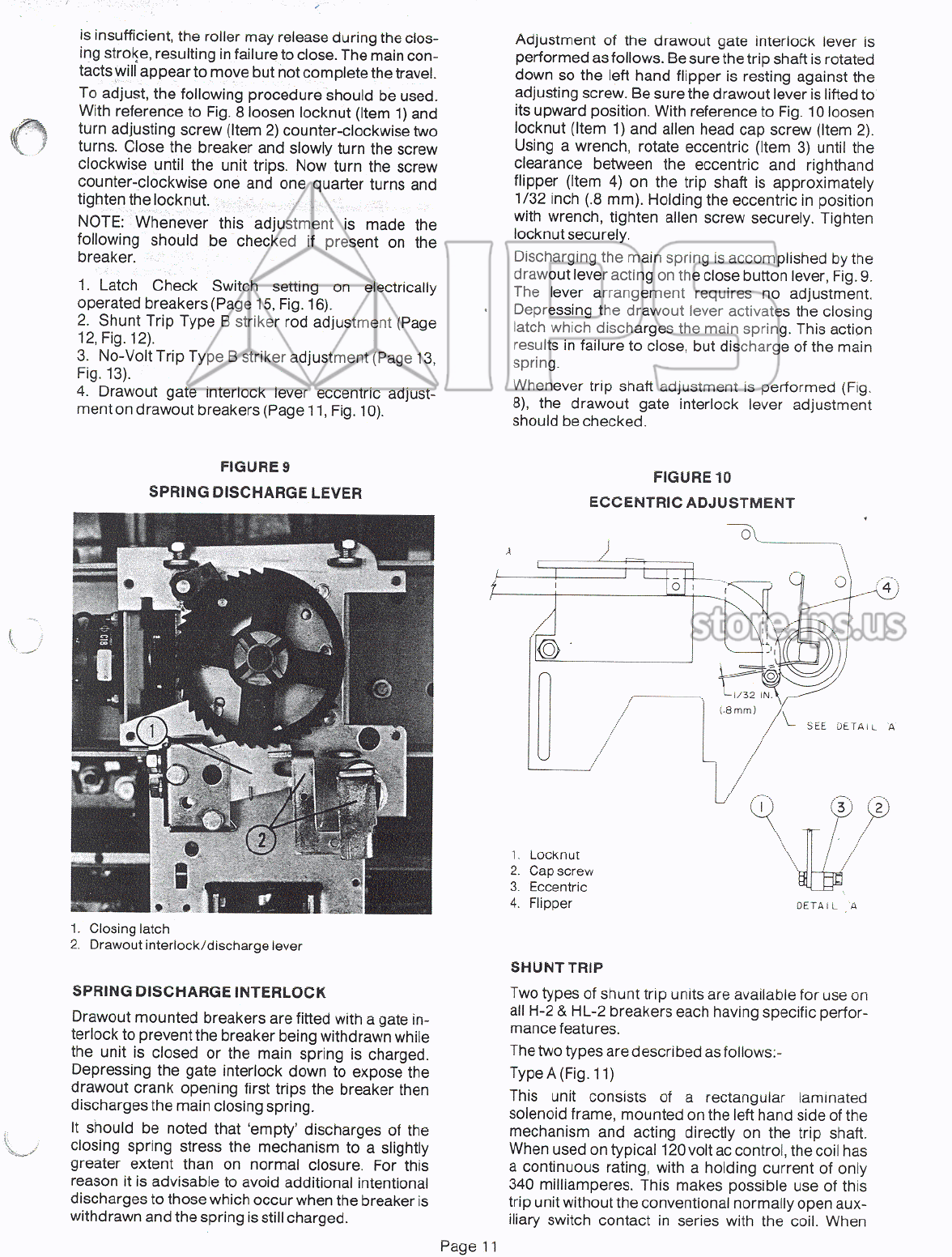
FIGURE
8
TRIP
SHAFT
ADJUSTMENT
FIGURE
7
LINKAGE
ECCENTRIC
ADJUSTMENT
5
.
r
'
tt
i
IV
—
^
5.2
mm
)
/
/
/
-
•
I
)
4
-
1
.
Locknut
2
.
Adjusting
Screw
r
i
Ik
i
i
!
;
„
r
.
T
.
The
adjustment
is
checked
by
charging
the
main
spring
with
the
breaker
closed
.
If
the
main
contacts
slowly
open
during
charging
,
the
eccentric
must
be
adjusted
to
move
the
toggle
pin
closer
to
the
stops
located
in
the
mechanism
sideplates
.
To
correct
C
-
Latch
roller
engagement
adjustment
must
be
made
.
This
adjustment
,
located
on
the
left
hand
side
of
the
mechanism
compartment
,
controls
the
engagement
of
the
trip
shaft
to
the
latch
roller
.
If
this
engagement
@
(
±
.
1
.
Spring
guide
clamp
pin
2
.
Main
spring
clamp
3
.
Locking
plate
4
.
Eccentric
5
.
Toggle
pin
6
.
Connecting
link
Page
10
Courtesy of store.ips.us
is
insufficient
,
the
roller
may
release
during
the
clos
-
ing
stroke
,
resulting
in
failure
to
close
.
The
main
con
-
tacts
will
appear
to
move
but
not
complete
the
travel
.
To
adjust
,
the
following
procedure
should
be
used
.
With
reference
to
Fig
.
8
loosen
locknut
(
Item
1
)
and
turn
adjusting
screw
(
Item
2
)
counter
-
clockwise
two
turns
.
Close
the
breaker
and
slowly
turn
the
screw
clockwise
until
the
unit
trips
.
Now
turn
the
screw
counter
-
clockwise
one
and
one
quarter
turns
and
tighten
the
locknut
.
NOTE
:
Whenever
this
adjustment
is
made
the
following
should
be
checked
if
present
on
the
breaker
.
1
.
Latch
Check
Switch
setting
on
electrically
operated
breakers
(
Page
15
,
Fig
.
16
)
.
2
.
Shunt
Trip
Type
B
striker
rod
adjustment
(
Page
12
,
Fig
.
12
)
.
3
.
No
-
Volt
Trip
Type
B
striker
adjustment
(
Page
13
,
Fig
.
13
)
.
4
.
Drawout
gate
interlock
lever
eccentric
adjust
-
ment
on
drawout
breakers
(
Page
11
,
Fig
.
10
)
.
Adjustment
of
the
drawout
gate
interlock
lever
is
performed
as
follows
.
Be
sure
the
trip
shaft
is
rotated
down
so
the
left
hand
flipper
is
resting
against
the
adjusting
screw
.
Be
sure
the
drawout
lever
is
lifted
to
its
upward
position
.
With
reference
to
Fig
.
10
loosen
locknut
(
Item
1
)
and
alien
head
cap
screw
(
Item
2
)
.
Using
a
wrench
,
rotate
eccentric
(
Item
3
)
until
the
clearance
between
the
eccentric
and
righthand
flipper
(
Item
4
)
on
the
trip
shaft
is
approximately
1
/
32
inch
(
.
8
mm
)
.
Holding
the
eccentric
in
position
with
wrench
,
tighten
alien
screw
securely
.
Tighten
locknut
securely
.
Discharging
the
main
spring
is
accomplished
by
the
drawout
lever
acting
on
the
close
button
lever
,
Fig
.
9
.
The
lever
arrangement
requires
no
adjustment
.
Depressing
the
drawout
lever
activates
the
closing
latch
which
discharges
the
main
spring
.
This
action
results
in
failure
to
close
,
but
discharge
of
the
main
spring
.
Whenever
trip
shaft
adjustment
is
performed
(
Fig
.
8
)
,
the
drawout
gate
interlock
lever
adjustment
should
be
checked
.
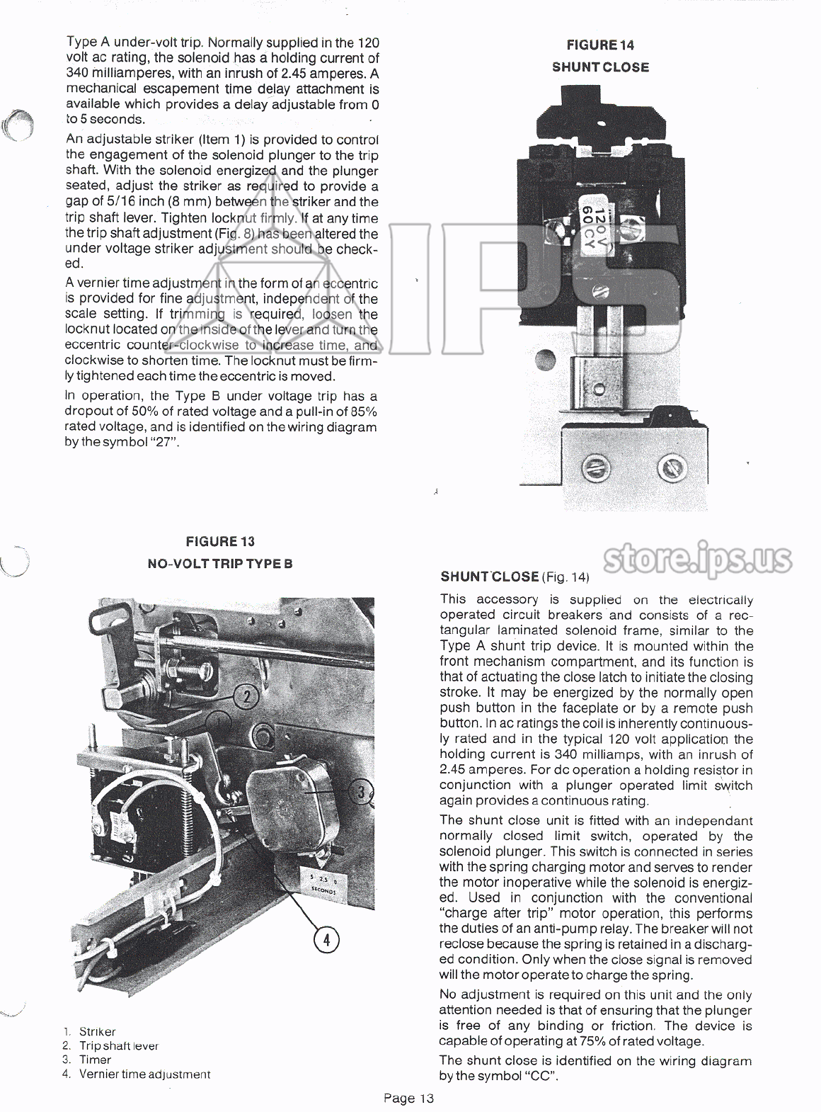
FIGURE
9
SPRING
DISCHARGE
LEVER
FIGURE
10
ECCENTRIC
ADJUSTMENT
~
"
sv
)
o
l
j
{
.
8
mm
)
SEE
DETAIL
A
/
/
/
1
.
Locknut
2
.
Capscrew
3
.
Eccentric
4
.
Flipper
DETAIL
A
1
.
Closing
latch
2
.
Drawout
interlock
/
discharge
lever
SHUNT
TRIP
Two
types
of
shunt
trip
units
are
available
for
use
on
all
H
-
2
&
HL
-
2
breakers
each
having
specific
perfor
-
mance
features
.
The
two
types
are
described
as
follows
:
-
Type
A
(
Fig
.
11
)
This
unit
consists
of
a
rectangular
laminated
solenoid
frame
,
mounted
on
the
left
hand
side
of
the
mechanism
and
acting
directly
on
the
trip
shaft
.
When
used
on
typical
120
volt
ac
control
,
the
coil
has
a
continuous
rating
,
with
a
holding
current
of
only
340
milliamperes
.
This
makes
possible
use
of
this
trip
unit
without
the
conventional
normally
open
aux
-
iliary
switch
contact
in
series
with
the
coil
.
When
SPRING
DISCHARGE
INTERLOCK
Drawout
mounted
breakers
are
fitted
with
a
gate
in
-
terlock
to
prevent
the
breaker
being
withdrawn
while
the
unit
is
closed
or
the
main
spring
is
charged
.
Depressing
the
gate
interlock
down
to
expose
the
drawout
crank
opening
first
trips
the
breaker
then
discharges
the
main
closing
spring
.
It
should
be
noted
that
‘
empty
’
discharges
of
the
closing
spring
stress
the
mechanism
to
a
slightly
greater
extent
than
on
normal
closure
.
For
this
reason
it
is
advisable
to
avoid
additional
intentional
discharges
to
those
which
occur
when
the
breaker
is
withdrawn
and
the
spring
is
still
charged
.
Page
11
Courtesy of store.ips.us

used
in
conjunction
with
a
typical
latching
-
type
ground
fault
relay
the
breaker
is
locked
out
and
will
be
totally
trip
-
free
until
the
relay
has
been
reset
.
Any
attempt
to
reclose
the
breaker
before
resetting
the
relay
will
preclude
a
restriking
of
the
ground
fault
.
No
adjustment
is
required
on
this
device
and
the
only
attention
needed
is
that
of
ensuring
that
the
plunger
is
free
of
any
binding
or
friction
.
This
unit
is
capable
of
tripping
at
50
%
of
the
rated
voltage
.
Type
B
(
Figure
12
)
This
is
a
cylindrical
solenoid
mounted
within
the
mechanism
comparment
at
the
lower
rear
and
ac
-
ting
directly
on
the
trip
shaft
.
Unlike
the
Type
A
unit
,
it
is
not
continuously
rated
and
for
any
application
a
normally
open
auxiliary
switch
contact
must
be
us
-
ed
.
In
the
120
volt
ac
application
the
Type
B
unit
is
equivalent
in
performance
to
the
Type
A
device
(
i
.
e
.
will
operate
at
50
%
of
rated
voltage
)
but
in
the
125
volt
dc
rating
,
tripping
can
be
performed
at
levels
as
low
as
25
%
of
nominal
rating
.
One
adjustment
is
provided
in
the
Type
B
trip
unit
to
control
the
extent
of
free
travel
between
the
plunger
and
the
trip
shaft
lever
.
By
lifting
the
plunger
until
the
striker
rod
is
lightly
touching
the
trip
shaft
lever
a
space
of
1
/
16
inch
(
1.6
mm
)
should
exist
between
the
end
of
the
plunger
and
the
stop
plate
as
shown
in
Figure
12
.
If
adjustment
is
required
,
loosen
the
8
-
32
socket
head
screw
located
at
the
bottom
end
of
the
plunger
,
and
turn
the
striker
rod
within
the
plunger
as
re
-
quired
.
Retighten
the
set
screw
.
If
trip
shaft
adjust
-
ment
(
Fig
.
8
)
is
altered
at
any
time
,
this
striker
rod
adjustment
should
be
checked
.
The
shunt
trip
is
identified
on
the
wiring
diagram
by
the
symbol
“
TC
”
.
Both
units
can
be
installed
on
one
breaker
.
With
regard
to
use
,
the
following
rules
are
usually
adhered
to
:
1
.
A
Type
B
is
used
where
only
a
separate
trip
coil
is
required
.
2
.
With
the
SD
relay
,
a
Type
B
is
used
between
the
mechanism
sideplates
to
operate
with
the
relay
,
and
possibly
a
Type
B
mounted
outside
the
left
hand
mechanism
sideplate
to
be
used
as
a
separate
trip
coil
.
3
.
A
Type
A
,
mounted
only
outside
the
left
hand
mechanism
sideplate
,
is
used
only
when
a
con
-
tinuous
rated
coil
for
a
separate
trip
source
is
re
-
quired
.
4
.
Type
A
and
Type
B
used
in
conjunction
with
the
SD
relay
can
both
be
used
on
the
same
unit
.
-
FIGURE
11
1
.
Shunt
trip
type
A
2
.
No
-
volt
trip
type
A
FIGURE
12
SHUNT
TRIPTYPEB
UNDER
VOLT
TRIP
-
TYPE
A
(
Fig
.
11
)
The
Type
A
Under
-
Volt
Trip
is
a
gravity
-
operated
device
mounted
on
the
left
hand
side
of
the
mechanism
compartment
and
acting
directly
on
the
trip
shaft
.
The
operating
solenoid
is
similar
to
the
Type
A
shunt
trip
,
and
is
normally
supplied
in
the
120
volt
ac
rating
,
with
a
holding
current
of
340
milliamperes
and
an
inrush
of
2.45
amperes
.
A
mechanical
escapement
time
delay
attachment
is
available
which
provides
a
delay
adjustable
from
0
to
5
seconds
.
In
operation
the
unit
has
a
dropout
of
50
%
of
rated
voltage
and
a
pull
in
of
85
%
of
rated
voltage
,
and
is
identified
on
the
wiring
diagram
by
the
symbol
“
27
”
UNDER
VOLT
TRIP
-
TYPE
B
(
Fig
.
13
)
Type
B
Under
Volt
Trip
is
a
spring
operated
unit
mounted
on
the
left
hand
side
of
the
main
mechanism
compartment
and
acting
directly
on
the
trip
shaft
.
In
operation
two
springs
are
held
in
com
-
pression
by
a
rectangular
solenoid
similar
to
the
u
1
.
Plunger
2
.
Stop
plate
Page
12
Courtesy of store.ips.us
Type
A
under
-
volt
trip
.
Normally
supplied
in
the
120
volt
ac
rating
,
the
solenoid
has
a
holding
current
of
340
milliamperes
,
with
an
inrush
of
2.45
amperes
.
A
mechanical
escapement
time
delay
attachment
is
available
which
provides
a
delay
adjustable
from
0
to
5
seconds
.
An
adjustable
striker
(
Item
1
)
is
provided
to
control
the
engagement
of
the
solenoid
plunger
to
the
trip
shaft
.
With
the
solenoid
energized
and
the
plunger
seated
,
adjust
the
striker
as
required
to
provide
a
gap
of
5
/
16
inch
(
8
mm
)
between
the
striker
and
the
trip
shaft
lever
.
Tighten
locknut
firmly
.
If
at
any
time
the
trip
shaft
adjustment
(
Fig
.
8
)
has
been
altered
the
under
voltage
striker
adjustment
should
be
check
-
FIGURE
14
SHUNTCLOSE
CJ
:
ON
)
!
ed
.
A
vernier
time
adjustment
in
the
form
of
an
eccentric
is
provided
for
fine
adjustment
,
independent
of
the
scale
setting
.
If
trimming
is
required
,
loosen
the
locknut
located
on
the
inside
of
the
lever
and
turn
the
eccentric
counter
-
clockwise
to
increase
time
,
and
clockwise
to
shorten
time
.
The
locknut
must
be
firm
-
ly
tightened
each
time
the
eccentric
is
moved
.
In
operation
,
the
Type
B
under
voltage
trip
has
a
dropout
of
50
%
of
rated
voltage
and
a
pull
-
in
of
85
%
rated
voltage
,
and
is
identified
on
the
wiring
diagram
by
the
symbol
“
27
”
.
FIGURE
13
NO
-
VOLT
TRIP
TYPE
B
SHUNT
CLOSE
(
Fig
.
14
)
This
accessory
is
supplied
on
the
electrically
operated
circuit
breakers
and
consists
of
a
rec
-
tangular
laminated
solenoid
frame
,
similar
to
the
Type
A
shunt
trip
device
.
It
is
mounted
within
the
front
mechanism
compartment
,
and
its
function
is
that
of
actuating
the
close
latch
to
initiate
the
closing
stroke
.
It
may
be
energized
by
the
normally
open
push
button
in
the
faceplate
or
by
a
remote
push
button
.
In
ac
ratings
the
coil
is
inherently
continuous
-
ly
rated
and
in
the
typical
120
volt
application
the
holding
current
is
340
milliamps
,
with
an
inrush
of
2.45
amperes
.
For
dc
operation
a
holding
resistor
in
conjunction
with
a
plunger
operated
limit
switch
again
provides
a
continuous
rating
.
The
shunt
close
unit
is
fitted
with
an
independant
normally
closed
limit
switch
,
operated
by
the
solenoid
plunger
.
This
switch
is
connected
in
series
with
the
spring
charging
motor
and
serves
to
render
the
motor
inoperative
while
the
solenoid
is
energiz
-
ed
.
Used
in
conjunction
with
the
conventional
“
charge
after
trip
”
motor
operation
,
this
performs
the
duties
of
an
anti
-
pump
relay
.
The
breaker
will
not
reclose
because
the
spring
is
retained
in
a
discharg
-
ed
condition
.
Only
when
the
close
signal
is
removed
will
the
motor
operate
to
charge
the
spring
.
No
adjustment
is
required
on
this
unit
and
the
only
attention
needed
is
that
of
ensuring
that
the
plunger
is
free
of
any
binding
or
friction
.
The
device
is
capable
of
operating
at
75
%
of
rated
voltage
.
The
shunt
close
is
identified
on
the
wiring
diagram
by
the
symbol
“
CC
”
.
1
.
Striker
2
.
Trip
shaft
lever
3
.
Timer
4
.
Vernier
time
adjustment
Page
13
Courtesy of store.ips.us
CLOSING
SPRING
CHARGING
MOTOR
All
electrically
operated
units
employ
a
series
-
wound
gear
motor
,
suitable
for
operation
on
alter
-
nating
or
direct
current
.
The
reduction
gear
com
-
partment
is
sealed
and
lubricated
for
life
and
the
ar
-
mature
bearing
similarly
requires
no
maintenance
lubrication
.
The
basic
motor
is
available
in
voltage
ratings
48
,
120
,
250
dc
and
120
,
240
ac
.
In
all
alter
-
nating
current
applications
above
240
V
a
step
down
control
transformer
is
used
in
conjunction
with
the
120
volt
motor
.
A
toggle
switch
mounted
in
the
faceplate
permits
the
motor
to
be
de
-
energised
during
maintenance
or
in
-
spection
.
(
Fig
.
2
)
.
Preferred
control
circuitry
permits
spring
charging
to
take
place
after
the
breaker
has
tripped
only
.
While
a
unit
can
be
supplied
to
charge
after
close
,
this
should
be
used
only
in
applications
requiring
high
speed
reclosing
.
Unless
otherwise
specified
all
units
are
supplied
to
operate
in
the
“
charge
after
trip
"
sequence
.
The
charging
motor
is
identified
on
the
wiring
diagram
by
the
symbol
“
M
”
.
To
remove
the
motor
,
first
remove
the
bracket
assembly
from
the
frame
channel
,
noting
the
number
of
shims
at
the
top
and
bottom
faces
of
the
motor
bracket
.
The
drive
cam
and
outboard
bearing
should
then
be
removed
.
The
drive
cam
is
threaded
to
the
motor
output
shaft
and
can
be
readily
releas
-
ed
by
a
light
tap
in
the
counter
clockwise
direction
.
Remove
the
hex
head
bolt
holding
the
front
bracket
to
the
motor
.
Next
,
remove
the
mounting
screws
at
the
end
opposite
to
the
drive
and
the
motor
housing
can
be
withdrawn
from
the
rear
bracket
.
When
replacing
the
motor
bracket
assembly
in
the
channel
,
replace
the
shims
as
originally
installed
.
Do
not
tighten
the
hex
head
bolt
holding
the
front
bracket
to
the
motor
until
the
screws
holding
the
motor
brackets
in
the
front
channel
have
been
tightened
securely
.
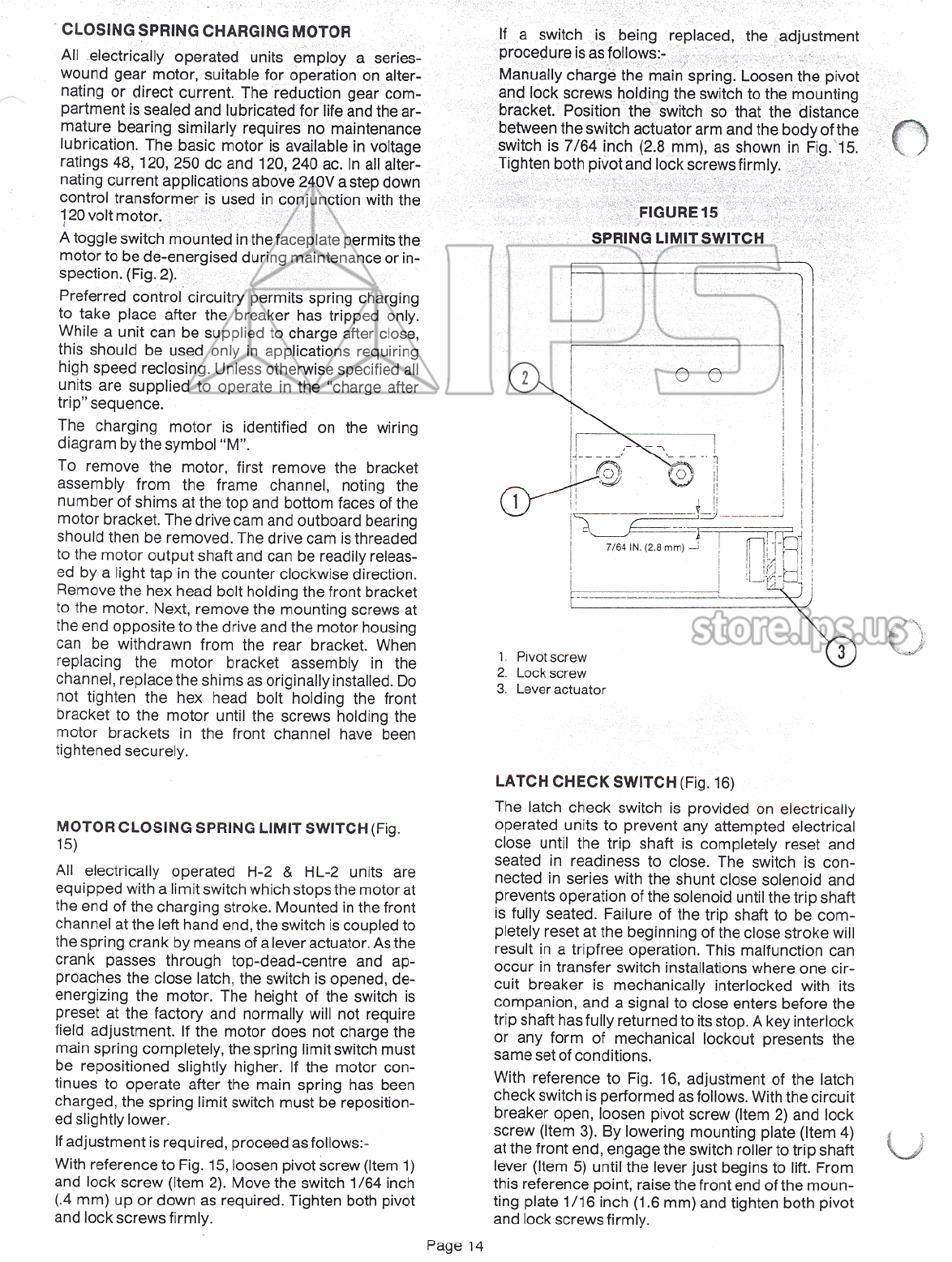
If
a
switch
is
being
replaced
,
the
adjustment
procedure
is
as
foliows
:
-
Manually
charge
the
main
spring
.
Loosen
the
pivot
and
lock
screws
holding
the
switch
to
the
mounting
bracket
.
Position
the
switch
so
that
the
distance
between
the
switch
actuator
arm
and
the
body
of
the
switch
is
7
/
64
inch
(
2.8
mm
)
,
as
shown
in
Fig
.
15
.
Tighten
both
pivot
and
lock
screws
firmly
.
FIGURE
15
SPRING
LIMIT
SWITCH
oo
2
;
H
i
1
rs
II
FlfF
7
/
64
IN
.
(
2.8
mm
)
\
~
(
A
H
i
JM
-
’
s
'
S
U
3
1
.
Pivot
screw
2
.
Lockscrew
3
.
Lever
actuator
LATCH
CHECK
SWITCH
(
Fig
.
16
)
The
latch
check
switch
is
provided
on
electrically
operated
units
to
prevent
any
attempted
electrical
close
until
the
trip
shaft
is
completely
reset
and
seated
in
readiness
to
close
.
The
switch
is
con
-
nected
in
series
with
the
shunt
close
solenoid
and
prevents
operation
of
the
solenoid
until
the
trip
shaft
is
fully
seated
.
Failure
of
the
trip
shaft
to
be
com
-
pletely
reset
at
the
beginning
of
the
close
stroke
will
result
in
a
tripfree
operation
.
This
malfunction
can
occur
in
transfer
switch
installations
where
one
cir
-
cuit
breaker
is
mechanically
interlocked
with
its
companion
,
and
a
signal
to
close
enters
before
the
trip
shaft
has
fully
returned
to
its
stop
.
A
key
interlock
or
any
form
of
mechanical
lockout
presents
the
same
set
of
conditions
.
With
reference
to
Fig
.
16
,
adjustment
of
the
latch
check
switch
is
performed
as
follows
.
With
the
circuit
breaker
open
,
loosen
pivot
screw
(
Item
2
)
and
lock
screw
(
Item
3
)
.
By
lowering
mounting
plate
(
Item
4
)
at
the
front
end
,
engage
the
switch
roller
to
trip
shaft
lever
(
Item
5
)
until
the
lever
just
begins
to
lift
.
From
this
reference
point
,
raise
the
front
end
of
the
moun
-
ting
plate
1
/
16
inch
(
1.6
mm
)
and
tighten
both
pivot
and
lock
screws
firmly
.
MOTOR
CLOSING
SPRING
LIMIT
SWITCH
(
Fig
.
15
)
All
electrically
operated
H
-
2
&
HL
-
2
units
are
equipped
with
a
limit
switch
which
stops
the
motor
at
the
end
of
the
charging
stroke
.
Mounted
in
the
front
channel
at
the
left
hand
end
,
the
switch
is
coupled
to
the
spring
crank
by
means
of
a
lever
actuator
.
As
the
crank
passes
through
top
-
dead
-
centre
and
ap
-
proaches
the
close
latch
,
the
switch
is
opened
,
de
-
energizing
the
motor
.
The
height
of
the
switch
is
preset
at
the
factory
and
normally
will
not
require
field
adjustment
.
If
the
motor
does
not
charge
the
main
spring
completely
,
the
spring
limit
switch
must
be
repositioned
slightly
higher
.
If
the
motor
con
-
tinues
to
operate
after
the
main
spring
has
been
charged
,
the
spring
limit
switch
must
be
reposition
-
ed
slightly
lower
.
If
adjustment
is
required
,
proceed
as
follows
:
-
With
reference
to
Fig
.
15
,
loosen
pivot
screw
(
Item
1
)
and
lock
screw
(
Item
2
)
.
Move
the
switch
1
/
64
inch
(
.
4
mm
)
up
or
down
as
required
.
Tighten
both
pivot
and
lock
screws
firmly
.
U
Page
14
Courtesy of store.ips.us
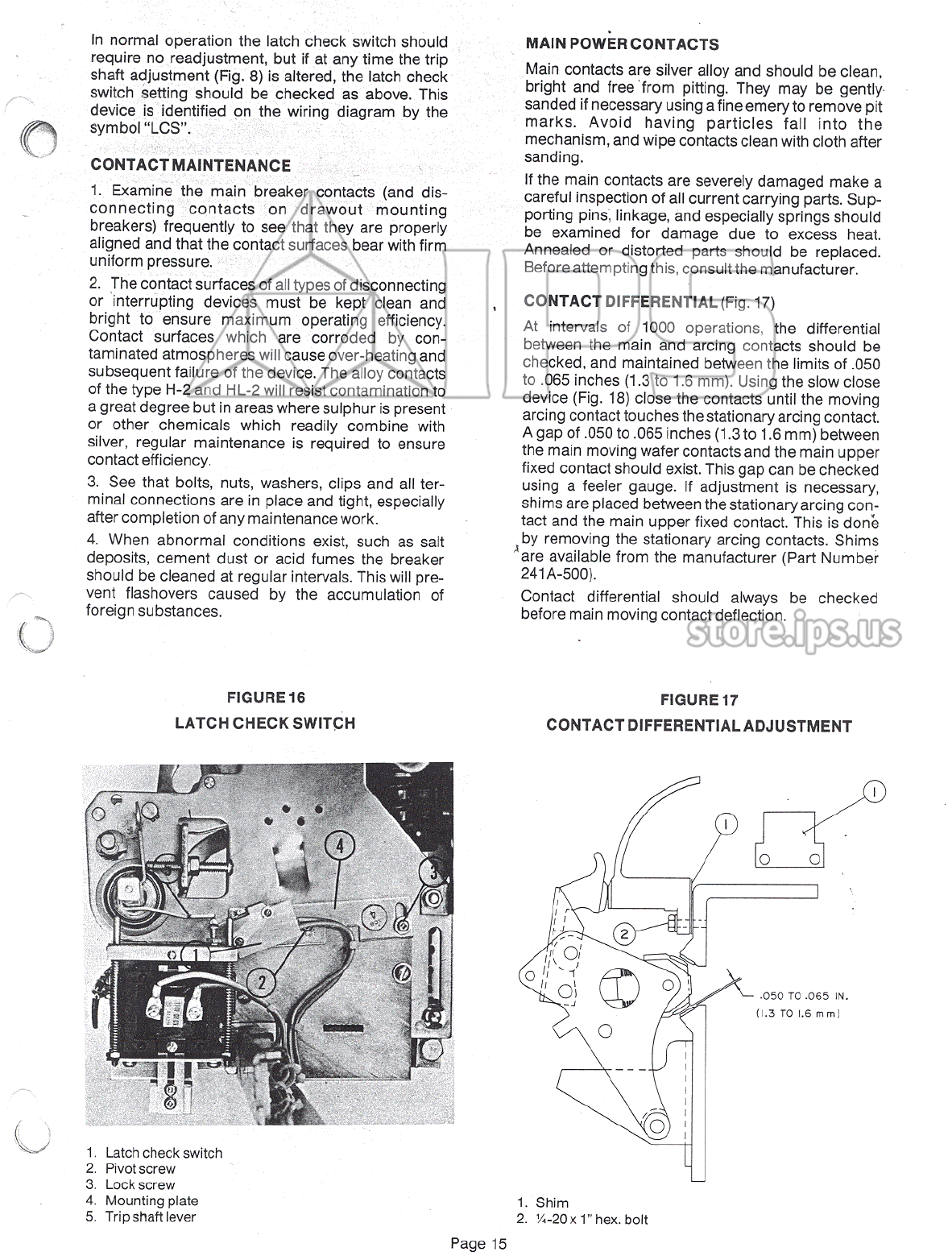
In
normal
operation
the
latch
check
switch
should
require
no
readjustment
,
but
if
at
any
time
the
trip
shaft
adjustment
(
Fig
.
8
)
is
altered
,
the
latch
check
switch
setting
should
be
checked
as
above
.
This
device
is
identified
on
the
wiring
diagram
by
the
symbol
“
LCS
”
.
MAIN
POWER
CONTACTS
Main
contacts
are
silver
alloy
and
should
be
clean
,
bright
and
free
from
pitting
.
They
may
be
gently
sanded
if
necessary
using
a
fine
emery
to
remove
pit
marks
.
Avoid
having
particles
fall
into
the
mechanism
,
and
wipe
contacts
clean
with
cloth
after
sanding
.
If
the
main
contacts
are
severely
damaged
make
a
careful
inspection
of
all
current
carrying
parts
.
Sup
-
porting
pins
,
linkage
,
and
especially
springs
should
be
examined
for
damage
due
to
excess
heat
.
Annealed
or
distorted
parts
should
be
replaced
.
Before
attempting
this
,
consult
the
manufacturer
.
CONTACT
DIFFERENTIAL
(
Fig
.
17
)
At
intervals
of
1000
operations
,
the
differential
between
the
main
and
arcing
contacts
should
be
checked
,
and
maintained
between
the
limits
of
.
050
to
.
065
inches
(
1.3
to
1.6
mm
)
.
Using
the
slow
close
device
(
Fig
.
18
)
close
the
contacts
until
the
moving
arcing
contact
touches
the
stationary
arcing
contact
.
A
gap
of
.
050
to
.
065
inches
(
1.3
to
1.6
mm
)
between
the
main
moving
wafer
contacts
and
the
main
upper
fixed
contact
should
exist
.
This
gap
can
be
checked
using
a
feeler
gauge
.
If
adjustment
is
necessary
,
shims
are
placed
between
the
stationary
arcing
con
-
tact
and
the
main
upper
fixed
contact
.
This
is
done
by
removing
the
stationary
arcing
contacts
.
Shims
^
are
available
from
the
manufacturer
(
Part
Number
241
A
-
500
)
.
Contact
differential
should
always
be
checked
before
main
moving
contact
deflection
.
CONTACT
MAINTENANCE
1
.
Examine
the
main
breaker
contacts
(
and
dis
-
connecting
contacts
on
drawout
mounting
breakers
)
frequently
to
see
that
they
are
properly
aligned
and
that
the
contact
surfaces
bear
with
firm
uniform
pressure
.
2
.
The
contact
surfaces
of
all
types
of
disconnecting
or
interrupting
devices
must
be
kept
clean
and
bright
to
ensure
maximum
operating
efficiency
.
Contact
surfaces
which
are
corroded
by
con
-
taminated
atmospheres
will
cause
over
-
heating
and
subsequent
failure
of
the
device
.
The
alloy
contacts
of
the
type
H
-
2
and
HL
-
2
will
resist
contamination
to
a
great
degree
but
in
areas
where
sulphur
is
present
or
other
chemicals
which
readily
combine
with
silver
,
regular
maintenance
is
required
to
ensure
contact
efficiency
.
3
.
See
that
bolts
,
nuts
,
washers
,
clips
and
all
ter
-
minal
connections
are
in
place
and
tight
,
especially
after
completion
of
any
maintenance
work
.
4
.
When
abnormal
conditions
exist
,
such
as
salt
deposits
,
cement
dust
or
acid
fumes
the
breaker
should
be
cleaned
at
regular
intervals
.
This
will
pre
-
vent
flashovers
caused
by
the
accumulation
of
foreign
substances
.
FIGURE
17
CONTACT
DIFFERENTIAL
ADJUSTMENT
FIGURE
16
LATCH
CHECK
SWITCH
oo
I
r
II
2
o
/
i
\
v
,
1
i
'
V
o
1
s
.
Il
o
05
.
050
TO
.
065
IN
.
(
1.3
TO
1.6
mm
)
O
1
.
Latch
check
switch
2
.
Pivot
screw
3
.
Lockscrew
4
.
Mounting
plate
5
.
Trip
shaft
lever
1
.
Shim
2
.
1
/
4
-
20
X
1
”
hex
.
bolt
Page
15
Courtesy of store.ips.us
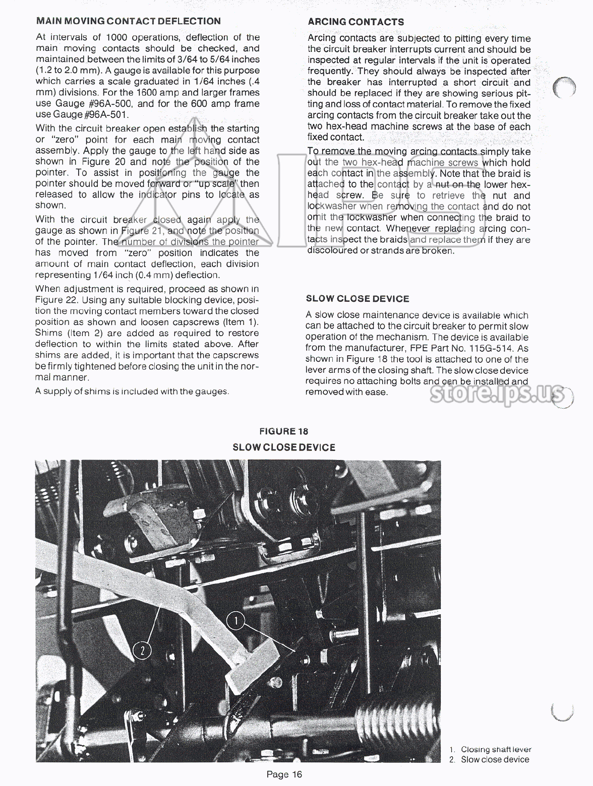
MAIN
MOVING
CONTACT
DEFLECTION
At
intervals
of
1000
operations
,
deflection
of
the
main
moving
contacts
should
be
checked
,
and
maintained
between
the
limits
of
3
/
64
to
5
/
64
inches
(
1.2
to
2.0
mm
)
.
A
gauge
is
available
for
this
purpose
which
carries
a
scale
graduated
in
1
/
64
inches
(
.
4
mm
)
divisions
.
For
the
1600
amp
and
larger
frames
use
Gauge
#
96
A
-
500
,
and
for
the
600
amp
frame
use
Gauge
#
96
A
-
501
.
With
the
circuit
breaker
open
establish
the
starting
or
“
zero
'
’
point
for
each
main
moving
contact
assembly
.
Apply
the
gauge
to
the
left
hand
side
as
shown
in
Figure
20
and
note
the
position
of
the
pointer
.
To
assist
in
positioning
the
gauge
the
pointer
should
be
moved
forward
or
“
up
scale
”
then
released
to
allow
the
indicator
pins
to
locate
as
shown
.
With
the
circuit
breaker
closed
again
apply
the
gauge
as
shown
in
Figure
21
,
and
note
the
position
of
the
pointer
.
The
number
of
divisions
the
pointer
has
moved
from
“
zero
”
position
indicates
the
amount
of
main
contact
deflection
,
each
division
representing
1
/
64
inch
(
0.4
mm
)
deflection
.
When
adjustment
is
required
,
proceed
as
shown
in
Figure
22
.
Using
any
suitable
blocking
device
,
posi
-
tion
the
moving
contact
members
toward
the
closed
position
as
shown
and
loosen
capscrews
(
Item
1
)
.
Shims
(
Item
2
)
are
added
as
required
to
restore
deflection
to
within
the
limits
stated
above
.
After
shims
are
added
,
it
is
important
that
the
capscrews
be
firmly
tightened
before
closing
the
unit
in
the
nor
-
mal
manner
.
A
supply
of
shims
is
included
with
the
gauges
.
ARCING
CONTACTS
Arcing
contacts
are
subjected
to
pitting
every
time
the
circuit
breaker
interrupts
current
and
should
be
inspected
at
regular
intervals
if
the
unit
is
operated
frequently
.
They
should
always
be
inspected
after
the
breaker
has
interrupted
a
short
circuit
and
should
be
replaced
if
they
are
showing
serious
pit
-
ting
and
loss
of
contact
material
.
To
remove
the
fixed
arcing
contacts
from
the
circuit
breaker
take
out
the
two
hex
-
head
machine
screws
at
the
base
of
each
fixed
contact
.
To
remove
the
moving
arcing
contacts
simply
take
out
the
two
hex
-
head
machine
screws
which
hold
each
contact
in
the
assembly
.
Note
that
the
braid
is
attached
to
the
contact
by
a
nut
on
the
lower
hex
-
head
screw
.
Be
sure
to
retrieve
the
nut
and
lockwasher
when
removing
the
contact
and
do
not
omit
the
lockwasher
when
connecting
the
braid
to
the
new
contact
.
Whenever
replacing
arcing
con
-
tacts
inspect
the
braids
and
replace
them
if
they
are
discoloured
or
strands
are
broken
.
SLOW
CLOSE
DEVICE
A
slow
close
maintenance
device
is
available
which
can
be
attached
to
the
circuit
breaker
to
permit
slow
operation
of
the
mechanism
.
The
device
is
available
from
the
manufacturer
,
FPE
Part
No
.
115
G
-
514
.
As
shown
in
Figure
18
the
tool
is
attached
to
one
of
the
lever
arms
of
the
closing
shaft
.
The
slow
close
device
requires
no
attaching
bolts
and
can
be
installed
and
removed
with
ease
.
FIGURE
18
SLOW
CLOSE
DEVICE
u
1
.
Closing
shaft
lever
2
.
Slow
close
device
Page
16
Courtesy of store.ips.us


This manual suits for next models
1
Other FEDERAL PIONEER Circuit Breaker manuals

Popular Circuit Breaker manuals by other brands


WEG
WEG FHU ACW125 installation instructions

TERASAKI
TERASAKI NHP TemBreak PRO P160 Series installation instructions

Siemens
Siemens Sentron 3VA9157-0PK1 Series operating instructions

hager
hager TS 303 User instruction

ETI
ETI EFI-4B Instructions for mounting

Gladiator
Gladiator GCB150 Installation instruction


