Delixi CDB6i User manual

CDB6i
User Manual
□Please carefully read this manual before the
installation and use of this product and keep it
properly for reference.

Safety Notice
Please carefully read this manual before the installation, operation, running, maintenance and inspection of
this product, and install and use this product properly in line with this manual.
Danger:
Do not operate the circuit breaker with your wet hands.
Do not touch the live part during operation.
Do not maintain and repair the live product.
Do not use the short-circuit method to test the product.
Attention:
The installation, maintenance and repair of the product should be carried out by the qualified
professionals.
Do not dismantle or adjust the product without permission during operation as all characteristics of
the product have been set at the factory;
Before use, confirm that the rated voltage, rated current, frequency and features of the product meet
the working requirements.
In order to prevent short circuit between phases, the bare wires or copper busbars of terminals should
be insulated;
If found damage or abnormal sound when unpacking, stop using the product immediately and contact
the supplier;
This product is not suitable for special occasions such as frequently started motors, electric heating
equipment, capacitor cabinets, high inductive or high capacitive loads and high temperature environments;
To scrap the product, the appropriate product waste disposal is required. Thanks for your cooperation.

Table of Contents
1 Main purposes and applications................................................................................................................... 1
2 Product features, model and meanings ........................................................................................................ 1
3 Normal use, installation and transport conditions........................................................................................ 2
3.1 Normal use and installation conditions............................................................................................. 2
3.2 Normal storage and transport conditions.......................................................................................... 2
4 Technical characteristics.............................................................................................................................. 2
4.1 Main technical performance parameters........................................................................................... 2
5 Outline and installation dimensions............................................................................................................. 3
6 Installation and use (maintenance)............................................................................................................... 3
7 Unpacking inspection .................................................................................................................................. 5
8 Company’s Commitment ............................................................................................................................. 5

1
1 Main purposes and applications
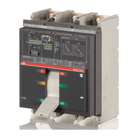
CDB6i series miniature circuit breakers are mainly used in circuits with AC 50/60Hz, rated voltage of not
exceeding 400/415V (phase-to-phase), and rated current ranged 1A~63A. This series of circuit breakers are
equipped with short-circuit protection release and overload protection release to provide short-circuit and
overload protection.
2 Product features, model and meanings
CDB 6i
Design Number
Miniature circuit breaker series
Panel description
Description:
1.Certification mark 2. Rated voltage 3.Rated frequency and Breaking capacity 4.Available standard
5.Power end 6. Company logo 7. Design serial number 8. Close break indication
9. Product model 10. Load side 11. Wiring principle diagram 12. Current specification (trip
type+rated current) 13 Contact indication
Note: When closing the handle normally, if the indicator window is not synchronized with the movement,

2
please stop using it.
3 Normal use, installation and transport conditions
3.1 Normal use and installation conditions
a) The upper limit of ambient air temperature does not exceed +70℃, the lower limit does not exceed -35℃,
and the average temperature within 24 hours does not exceed +35℃;
b) The altitude of the installation site does not exceed 2000m;
c) When the temperature is +40°C, the relative humidity of the air does not exceed 50%; at a lower
temperature, a greater relative humidity is allowed. For example, at +20°C, the relative humidity does not
exceed 90%. Special protective measures shall be taken for the condensation produced occasionally due to
temperature changes;
d) The external magnetic field near the circuit breaker installation site should not exceed 5 times the
geomagnetic field in any direction;
e) Installed in a medium without explosion hazard, and there is no enough gas and dust that cause corrosion
to metals and destroy to insulation in the medium;
f) Installed in the place without significant impact vibration and rain and snow invasion;
g) Pollution level: Level 2;
h) Installation category: CategoryⅡ, Category Ⅲ;
i) Installed in the power distribution box, electric distribution cabinet or box;
j) Reverse wiring is allowed for product;
k) When wiring products with N pole, connect the neutral wire (zero line) to the pole marked with N.
3.2 Normal storage and transport conditions
a) The lower temperature limit is not less than -40℃, and the upper limit is not more than +85℃;
b) Relative humidity (at 25℃) does not exceed 95%;
c) Handle the product gently during transport, do not upside it down and try to avoid violet collisions.
4 Technical characteristics
4.1 Main technical performance parameters
a) The main technical parameters of the circuit breaker see Table 1
Table 1 Main technical parameters
Trip type
Rated current In A
Number of poles
Rated voltage Ue V
Rated breaking capacity Icn A
B、C、D
1、2、3、4、5、6、8、
10、13、16、20、25、
32、40、50、63
1P
AC230/400V
AC240/415V
6kA
1P+N
AC230/240V
2P
AC400/415V
3P
3P+N
4P
b) Overcurrent protection characteristics of circuit breakers are shown in Table 2
Table 2 Overcurrent protection characteristics of circuit breaker
Release type
Rated current
In A
Test current
A
Starting state
Starting
time
Expected
results
Remarks
Reference
temperature
B, C, D
≤63
1.13In
Cold state
t≤1h
No trip
℃
B, C, D
≤63
1.45In
Immediate test
t<1h
Trip
Current rises to
the specified
value within 5s
B, C, D
≤32
2.55In
Cold state
1s<t<60s
Trip
B, C, D
>32
1s<t<120s
B
≤63
3In
Cold state
t≤0.1s
No trip
Turn on the
auxiliary switch to
power on
C
5In
D
10In
B
≤63
5In
Cold state
t<0.1s
Trip
Turn on the
auxiliary switch to
C
10In

3
D
14In
power on
c) The protection characteristic curves of the circuit breaker are shown in Fig. 1 and Fig. 2, respectively.
Fig. 1 B type
thermal/electromagnetic trip
characteristic curve
Fig. 2 C type
thermal/electromagnetic trip
characteristic curve
Fig. 3 D type
thermal/electromagnetic trip
characteristic curve
5 Outline and installation dimensions
The outline and installation dimensions see Fig. 3. Unit:mm
Fig. 3 Outline and installation dimensions
6 Installation and use (maintenance)
Before installing the circuit breaker:
a) Check whether the technical parameters on the printed sign meet the use requirements;
b) Before use, users should check that the insulation resistance between poles (expect for single pole), pole
and housing, pole and mounting rail, incoming terminal and outgoing terminal with a 500V megohmmeter
should not be less than 5MΩ. If the insulation resistance is less than 5MΩ, do not use the product and
contact the supplier for timely replacement;
c) Close and open the circuit breaker several times to check the circuit breaker operating mechanism for
blockage and for reliable action;
d) The reference temperature of this series of circuit breakers is
℃. If multiple circuit breakers are
installed in the sealed box, the temperature inside the box will increase accordingly, and the use current is
0.8In;
e) The cross-sectional area of the connecting wire should be compatible with the rated current of the circuit

4
breaker, as shown in Table 3;
Table 3 Rated current and the cross-sectional area of connecting wires
Rated current value A
1, 2, 3, 4, 5, 6
8, 10
13, 16, 20
25
32
40, 50
63
Wire cross-sectional area mm²
1
1.5
2.5
4
6
10
16
Wiring tightening torque N .m
2.0 for power end and load end
f) This series of circuit breakers are rail-mounted, and TH35-7.5 steel mounting rails are available.
g) When the ambient temperature changes, the rated current value is corrected accordingly, and the
temperature correction coefficients are listed in Table 4;
Table 4 Rated current and temperature correction coefficient table
Rated
current A
Corrected value of rated currentA
-35℃
-20℃
-10℃
0℃
10℃
20℃
30℃
40℃
50℃
60℃
70℃
1
1.27
1.22
1.18
1.15
1.10
1.05
1
0.94
0.90
0.84
0.81
2
2.54
2.43
2.31
2.25
2.17
2.06
2
1.93
1.85
1.63
1.61
3
3.81
3.68
3.57
3.43
3.29
3.18
3
2.82
2.63
2.57
2.45
4
5.08
4.89
4.75
4.67
4.48
4.24
4
3.98
3.52
3.25
3.22
5
6.35
6.21
5.98
5.83
5.77
5.42
5
4.85
4.57
4.19
4.05
6
7.62
7.33
7.05
6.84
6.62
6.30
6
5.64
5.42
5.06
4.86
8
10.08
9.78
9.44
9.15
8.51
7.98
8
7.1
6.92
6.75
6.48
10
12.60
12.25
11.87
11.64
11.15
10.62
10
9.30
8.96
8.48
8.10
13
16.38
15.78
15.34
14.83
14.22
13.75
13
12.10
11.75
10.93
10.52
16
20.16
19.49
18.72
18.06
17.98
16.96
16
15.04
14.42
13.47
12.96
20
25.20
24.35
23.68
22.82
22.47
21.20
20
18.80
17.85
16.78
16.20
25
31.50
30.52
29.61
28.78
28.09
26.50
25
23.25
22.52
21.02
20.25
32
40.32
38.96
37.68
36.62
35.96
33.92
32
30.08
28.81
26.84
26.20
40
50.40
48.85
47.13
46.32
45.80
42.80
40
36.80
36.21
33.5
32.40
50
63.50
61.58
59.52
57.35
55.04
52.59
50
46
44.25
42.36
40.50
63
79.38
76.86
74.25
71.18
69.13
67.41
63
58.59
56.83
52.93
51.03
h) When the handle moves upwards, this means that the circuit is in the ON state; when the handle moves
downwards, this means that the circuit is in the OFF state;
i) Insert the residual current operated circuit breaker into the mounting rail until it is fixed on the rail without
any looseness or falling off. To remove the residual current operated circuit breaker, push it upward
forcedly and pull its upper portion outwards until the circuit beaker is removed from the mounting rail.
Maintenance and repair:
a) The maintenance and repair of the product must be performed by qualified professionals;
b) Do not maintain or repair the live product;
c) Maintain the product once a year under normal operating conditions.The maintenance contents see Table
5.

5
Table 5 Maintenance and Repair
Item
Contents
Appearance
No dust, no condensation; remove them
if necessary
No damage
No change in colors of the housing and
wiring terminal
Connection of the wiring
terminal
Tighten it according to the torque
specified in Table 3 without any
looseness
Handle ON/OFF
operatoin
Flexible action
7 Unpacking inspection
After unpacking, user must check whether the product is intact, whether the exposed metal parts are rusted, and
whether the product is defected due to poor transport or storage. If found one of the above situations, please
contact the supplier in time for solution.
8 Company’s Commitment
Under the premise that the user complies with the use and storage conditions and that the product is well sealed,
if the product is damaged or cannot work normally due to poor manufacturing quality within 36 months from
the production date, our company will repair or replace the product free of charges. When the warranty period
expires, a paid repair is provided. For any damage caused by one of the following situations, a paid repair is
given even within the warranty period:
a) Improper use, maintenance or storage;
b) Modify without permission, improper repair;
c) Damage caused by product falling off and during installation process after purchase;
d) Force majeures such as earthquake, fire, lightning stroke, abnormal voltage and secondary disaster.
If you have any question, please contact the dealer or our company’s customer service department. Customer
service hotline: 400-826-8008

6
DELIXI High-Tech Industrial Park, Liushi Town, Yueqing City, Zhejiang Zip: 325604
Tel: (86-577) 61778888
Fax: (86-577) 61778000
Customer Service Hotline: 400-826-8008
www.delixi-electric.com
This Manual will be issued in Step. 2022 First Edition
Table of contents
Other Delixi Circuit Breaker manuals


