Effective 8/2006
Page 1
I.L. 66A7534H04
1.0 GeneralDescriptionofDigitripTripUnits ................. 2
1.1 Protection ............................................................... 3
1.2 ModeofTripandStatusInformation ........................ 3
1.3 InstallationandRemoval.......................................... 3
1.3.1 InstallationoftheTripUnit............................ 3
1.3.2 Installationofthe Rating Plug....................... 3
1.3.3 TripUnit/Rating Plug Removal...................... 4
1.4 InstallingtheCHType-VCurentSensors................. 5
1.4.1 Installation of the Rating Plug...................... 5
1.4.2 CH Type-V Current Sensor Functiionality .... 5
1.5 PlexiglassCover ..................................................... 5
1.6 GroundAlarm/PowerSupply Module (520MCV)....... 5
1.6.1 Auxilary Power ............................................ 7
1.6.2 GroundAlarm .............................................. 7
1.6.3 Ground Fault Trip ........................................ 7
1.6.4 Ground FaultAlarm ..................................... 7
1.7 DisplayFeature(520MCV) ...................................... 7
1.8 UL,CSAandCERecognition.................................. 8
2.0 GeneralDescriptionof VCP-T,VCP-TR
andT-VAC,T-VACRCircuit Breakers....................... 8
2.1 General ................................................................... 8
2.2 LowEnergyTripActuator ........................................ 9
2.3 GroundFaultProtection .......................................... 9
2.3.1 General ........................................................ 9
2.3.2 Zero SequenceSensing ............................... 9
2.3.3 ResidualSensing......................................... 9
2.3.4 GroundFaultSettings................................ 10
3.0 PrinciplesofOperation .......................................... 12
3.1 General ................................................................. 12
3.2 TripandOperationIndicators................................. 12
3.3 ZoneInterlocking ............................................. 12, 28
4.0 Protection Settings ............................................... 14
4.1 General ................................................................. 14
4.2 LongDelayCurrentSetting ................................... 14
4.3 LongDelayTimeSetting ....................................... 14
4.4 ShortDelayCurrentSetting................................... 15
4.5 ShortDelay TimeSetting ...................................... 15
4.6 InstantaneousCurrentSetting ............................... 15
4.7 GroundFaultCurrentSetting................................. 16
4.8 GroundFaultTimeDelaySetting .......................... 16
4.9 INCOM(520MCV).................................................. 16
4.9.1 Breaker InterfaceModule (BIM) .................. 16
4.9.2 Remote MasterComputer .......................... 16
4.9.3 INCOM NetworkInterconnections .............. 17
5.0 TestProcedures .................................................... 18
5.1 TestPrecautions ................................................... 18
5.2 When to Test ........................................................ 18
5.3 FunctionalFieldTesting ........................................ 18
5.3.1 Field Test Kit............................................... 18
5.3.2 Handheld Functional Test Kit...................... 19
5.3.2.1 Description of HandheldTest Kit...... 19
5.3.2.2 Test Procedure................................ 19
5.3.2.3 Currents .......................................... 19
5.3.2.4 Batteries ......................................... 19
5.4 PerformanceTesting of DigitripTripUnits .............. 19
5.4.1 General ...................................................... 19
5.4.2 Testing using MS-2 MultiAMP®Tester....... 19
5.4.2.1 Description of MS-2 Tester .............. 19
5.4.2.2 Primary Injection Testing ................. 20
5.4.2.3 Secondary InjectionTesting............. 21
6.0 Battery ................................................................. 23
6.1 General ................................................................. 23
6.2 Battery Check ....................................................... 23
6.3 Battery Installation and Removal ........................... 23
7.0 FrameRatings
(SensorRatingsandRatingPlugs)....................... 24
8.0 RecordKeeping .................................................... 24
9.0 References............................................................ 24
9.1 MediumVoltageTypeVCPCircuit Breakers.......... 24
9.2 Time-CurrentCurves .............................................. 24
AppendixA Zone Interlocking Examples..................... 28
AppendixB TroubleshootingGuide ............................ 30
Appendix C Typical Breaker Master
Connection Diagram................................ 32
Appendix D MODBUS Translator Wiring .................... 33
Manufacturer’sStatement ............................................. 34
I.L. 66A7534H04
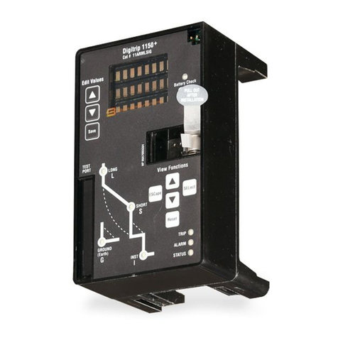
Instructions for Digitrip Models 520V and 520MCV
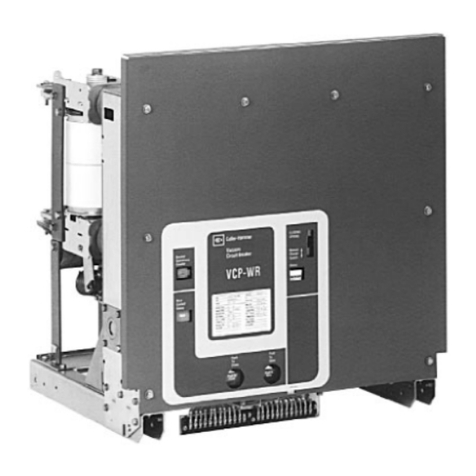
for use only in Cutler-Hammer Type VCP-T, VCP-TR
and T-VAC, T-VACR Circuit Breakers
Table of Contents

