manuals.online logo
Brands
  1. Home
  2. •
  3. Brands
  4. •
  5. Siemens
  6. •
  7. Circuit Breaker
  8. •
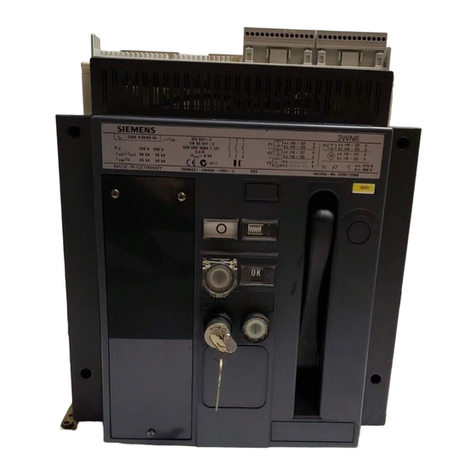
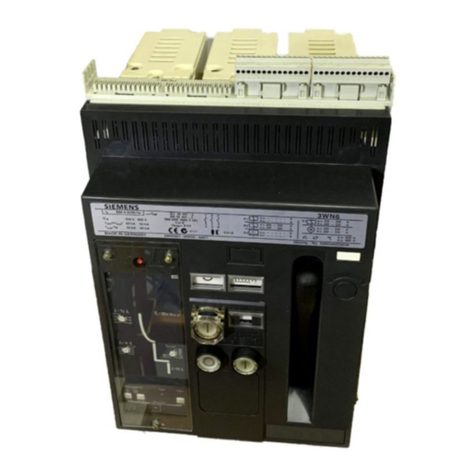
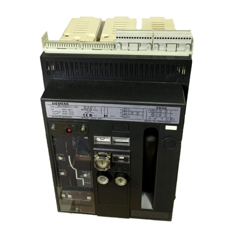
  9. Siemens 3WN6 User manual

Siemens 3WN6 User manual

1
Alle Rechte vorbehalten. All rights reserved. Tous droits réservés. Nos reservamos todos los derechos.
Tutti i diretti riservati. All rätt förbehålles.
© Siemens AG 1995
Anschlußschienen für Festeinbauschalter 3WX3621-1 . . 0 .
Connecting bars for fixed-mounted circuit breaker
Barrettes de raccordement pour berceau de débrochage
Piezas de conexión terruptores fijios
Sbarre di allacciamento per interruttori in esecuzione fissa
Anslutningsskenor för fast monterad brytare
123 4
567 8
910 1211
13 14 17 191816
15
3WN63WN6
Gefahr!
Gefährliche Spannung!
Gefährlicher Federspeicher!
VorBeginnderArbeitenGerätspannungsfreischalten
und gegen Wiedereinschalten sichern.
Bei Nichtbeachtung können Tod, schwere Körperver-
letzungodererheblicherSachschadendieFolge sein.
Einbau und Montage nur durch Fachpersonal!
Hazardous voltage!
Hazardous spring pressure
Before beginning work on the unit, switch it to a de-
energized state and secure it against reactivation.
Non-observance can result in death, severe personal
injury or substantial property damage.
Onlyqualifiedpersonnelmay performinstallation and
assembly work.
Danger!
English
Deutsch
Anschlußschienen mit Standardlochbild:
1 Anschlußschiene BG I, <=1000 A
2 Anschlußschiene BG I, 1250-1600 A
3 Anschlußschiene BG II, <=2000 A
4 Anschlußschiene BG II, 2500-3200 A
Anschlußschienen mit DIN-Lochbild:
5 Anschlußschiene BG I, <=1000 A
6 Anschlußschiene BG I, 1250-1600 A
7 Anschlußschiene BG II, <=2000 A
8 Anschlußschiene BG II, 2500-3200 A
9 Druckplatte
10 Abstandsstück
11 Sechskantschraube DIN 931 - M 10 x 40 - 8
12 Sechskantschraube DIN 931 - M 10 x 55 - 8
13 Zylinderschraube DIN 912 - M 6 x 30 - 8
14 Zylinderschraube DIN 912 - M 6 x 40 - 8
15 Zylinderschraube DIN 912 - M 6 x 45 - 8
16 Zylinderschraube DIN 912 - M 6 x 55 - 8
17 Spannscheibe DIN 6796 - 10 - St
18 Spannscheibe DIN 6796 - 6 - St
19 Sechskantmutter DIN 934 - M 10 - 8
Connecting bars with standard hole pattern:
1 Connecting bar size I, <=1000 A
2 Connecting bar size I, 1250-1600 A
3 Connecting bar size II, <=2000 A
4 Connecting bar size II, 2500-3200 A
Connecting bars with DIN hole pattern:
5 Connecting bar size I, <=1000 A
6 Connecting bar size I, 1250-1600 A
7 Connecting bar size II, <=2000 A
8 Connecting bar size II, 2500-3200 A
9 Pressure plate
10 Spacer
11 Hexagon-head bolt DIN 931 - M 10 x 40 - 8
12 Hexagon-head bolt DIN 931 - M 10 x 55 - 8
13 Fillister-head screw DIN 912 - M 6 x 30 - 8
14 Fillister-head screw DIN 912 - M 6 x 40 - 8
15 Fillister-head screw DIN 912 - M 6 x 45 - 8
16 Fillister-head screw DIN 912 - M 6 x 55 - 8
17 Strain washer DIN 6796 - 10 - St
18 Strain washer DIN 6796 - 6 - St
19 Hexagonal nut DIN 934 - M 10 - 8
Packungsinhalt überprüfen
Check contents of pack
Stückzahlen siehe Tabellen Seite 2/
For quantities see table on page 2
Betriebsanleitung/Operating Instructions Bestell-Nr./Order No.: 3ZX1812-0WX36-7AA0 / 9239 9802 422
2
Bestell-Nr.
der Packeinheit für Schalter-
baugröße Bemessungs-
strom Einzelteil-Nr.
Order no. of
Packing unit For size Rated current Part no.
A 1 2 3 4 9 10 11 12 13 14 15 16 17 18 19
3WX3621-1AA00 I ≤1000 1 1 1 2 2 2 2 2 2
-1AB00 3 3 3 6 6 6 6 6 6
-1AC00 4 4 4 8 8 8 8 8 8
-1AD00 6 6 6 12 6 6 12 12 12
-1AE00 8 8 8 16 8 8 16 16 16
-1BA00 1250-1600 1 1 2 2 2 2 2
-1BB00 3 3 6 6 6 6 6
-1BC00 4 4 8 8 8 8 8
-1BD00 6 6 12 6 6 12 12
-1BD00 8 8 16 8 8 16 16
-1DA00 II ≤2000 1 2 2 2 2 2
-1DB00 3 6 6 6 6 6
-1DC00 4 8 8 8 8 8
-1DD00 6 12 6 6 12 12
-1DE00 8 16 8 8 16 16
-1FA00 2500-3200 1 2 2 2 2 2
-1FB00 3 6 6 6 6 6
-1FC00 4 8 8 8 8 8
-1FD00 6 12 6 6 12 12
-1FE00 8 16 8 8 16 16
Bestell-Nr.
der Packeinheit für Schalter-
baugröße Bemessungs-
strom Einzelteil-Nr.
Order no. of
Packing unit For size Rated current Part no.
A 5 6 7 8 9 10 11 12 13 14 15 16 17 18 19
3WX3621-1AA01 I ≤1000 1 1 1 2 2 2 2 2 2
-1AB01 3 3 3 6 6 6 6 6 6
-1AC01 4 4 4 8 8 8 8 8 8
-1AD01 6 6 6 12 6 6 12 12 12
-1AE01 8 8 8 16 8 8 16 16 16
-1BA01 1250-1600 1 1 2 2 2 2 2
-1BB01 3 3 6 6 6 6 6
-1BC01 4 4 8 8 8 8 8
-1BD01 6 6 12 6 6 12 12
-1BD01 8 8 16 8 8 16 16
-1DA01 II ≤2000 1 2 2 2 2 2
-1DB01 3 6 6 6 6 6
-1DC01 4 8 8 8 8 8
-1DD01 6 12 6 6 12 12
-1DE01 8 16 8 8 16 16
-1FA01 2500-3200 1 2 2 2 2 2
-1FB01 3 6 6 6 6 6
-1FC01 4 8 8 8 8 8
-1FD01 6 12 6 6 12 12
-1FE01 8 16 8 8 16 16
Bestell-Nr. der Packeinheit
Order No. of packing unit
N°de réf
Referencia del paquete
Nr. di ordinazione dell’imballo
Förpackningens
beställningsnummer
für Schalterbaugröße
For size
Taille disjoncteur
para tamaño
Dimensione dell’ interruttore
För brytarstorlek
Bemessungsstrom
Rated current
Courant assigné
Intensidad asignada
Corrente nominale
Märkström
Einzelteil-Nr.
Part no.
N°de piece Qté
Cantidad de unidades
Nr. dei singoli pezzi
Detalj nr.
Einzelteilstückzahlen für Anschlußschienen mit Standardlochbild / Component quantities for connecting bars with
standard hole plattern / Jeu de pièces contenu dans l' emballage des barettes de raccordement avec schéma de
percages standard / Cantidad de unidades para de conexión con agujeros estándar /
Numero dei singoli pezzi per sbarre di allacciamento con disposizione standard dei fori /
Antal komponenter för anslutningsskenor med standardhålmönster
EinzelteistückzahlenfürAnschlußschienenmitDIN-Lochbild/ComponentquantitiesforconnectingbarswithDINhole
plattern / Jeu de pièces contenu dans l' emballage des barettes de raccordement avec schéma de percages DIN
Cantidad de unidades para de conexión con agujeros DIN / Numero dei singoli pezzi per sbarre di allacciamento con
disposizione dei fori secondo DIN / Antal komponenter för anslultningsskenor med DIN-hålmönster
Bestell-Nr. der Packeinheit
Order No. of packing unit
N°de réf
Referencia del paquete
Nr. di ordinazione dell’imballo
Förpackningens
beställningsnummer
für Schalterbaugröße
For size
Taille disjoncteur
para tamaño
Dimensione dell’ interruttore
För brytarstorlek
Bemessungsstrom
Rated current
Courant assigné
Intensidad asignada
Corrente nominale
Märkström
Einzelteil-Nr.
Part no.
N°de piece Qté
Cantidad de unidades
Nr. dei singoli pezzi
Detalj nr.
Deutsch
English
Français
Español
Italiano
Svenska
3
1) Schrauben und Spannscheiben vor der Montage der betreffenden Anschlußschiene entfernen!
1) Remove bolts and strain washers before fitting the relevant connecting bar!
Anzugsreihenfolge:
1. 15 handfest
2. 11 mit 40±4 Nm
3. 15 mit 8±1 Nm
Tightening sequence:
1. 15 hand-tight
2. 11 with 40±4 Nm
3. 15 with 8±1 Nm
Anzugsreihenfolge:
1. 15 handfest
2. 11 mit 40±4 Nm
3. 15 mit 8±1 Nm
Tightening sequence:
1. 15 hand-tight
2. 11 with 40±4 Nm
3. 15 with 8±1 Nm
11;17
Anzugsreihenfolge:
1. 16 handfest
2. 11 mit 40±4 Nm
3. 16 mit 8±1 Nm
Tightening sequence:
1. 16 hand-tight
2. 11 with 40±4 Nm
3. 16 with 8±1 Nm
Anzugsreihenfolge:
1. 16 handfest
2. 12 mit 40±4 Nm
3. 14 mit 8±1 Nm
Tightening sequence:
1. 16 hand-tight
2. 12 with 40±4 Nm
3. 14 with 8±1 Nm
Baugröße I, 1250-1600 A
Size I, 1250-1600 A
2
10
15;18
6
11
17
18 16
10
2
6
1)
Baugröße II, 2500-3200 A
Size II, 2500-3200 A
4
8
14;18
12;17
Anzugsreihenfolge:
1. 14 handfest
2. 12 mit 40±4 Nm
3. 14 mit 8±1 Nm
Tightening sequence:
1. 14 hand-tight
2. 12 with 40±4 Nm
3. 14 with 8±1 Nm
17
12
18 16
4
8
1)
Anzugsreihenfolge:
1. 16 handfest
2. 11 mit 40±4 Nm
3. 16 mit 8±1 Nm
Tightening sequence:
1. 16 hand-tight
2. 11 with 40±4 Nm
3. 16 with 8±1 Nm
Anzugsreihenfolge:
1. 13 handfest
2. 19 mit 40±4 Nm
3. 13 mit 8±1 Nm
Tightening sequence:
1. 13 hand-tight
2. 19 with 40±4 Nm
3. 13 with 8±1 Nm
Baugröße I, ≤1000 A
Size I, ≤1000 A
5
1
10
13;18
9;11
17;19
11
17
10
1
5
1)
19
18 15
9
Baugröße II, ≤2000 A
Size II, ≤2000 A
Anzugsreihenfolge:
1. 14 handfest
2. 11 mit 40±4 Nm
3. 14 mit 8±1 Nm
Tightening sequence:
1. 14 hand-tight
2. 11 with 40±4 Nm
3. 14 with 8±1 Nm
1)
3
7
14;18
11;17
17
11
18 16
3
7
Hinweis: Lage der Spannscheiben beachten!
Note: Locate strain washers correctly
Anschlußschienen montieren
Fit the connecting bars
Deutsch
English
4
123
910
13 14 16
15
567
1211
17 1918
4
8
Piezas de conexión con configuración de agujeros estándar :
1 Pieza de conexión tamaño I, <=1000 A
2 Pieza de conexión tamaño I, 1250-1600 A
3 Pieza de conexión tamaño II, <=2000 A
4 Pieza de conexión tamaño II, 2500-3200 A
Piezas de conexión con configuración de agujeros estándar :
5 Pieza de conexión tamaño I, <=1000 A
6 Pieza de conexión tamaño I, 1250-1600 A
7 Pieza de conexión tamaño II, <=2000 A
8 Pieza de conexión tamaño II, 2500-3200 A
9 Placa de presión
10 Distanciador
11 Tornillo hexagonal DIN 931 - M 10 x 40 - 8
12 Tornillo hexagonal DIN 931 - M 10 x 55 - 8
13 Tornillo cilindrico DIN 912 - M 6 x 30 - 8
14 Tornillo cilindrico DIN 912 - M 6 x 40 - 8
15 Tornillo cilindrico DIN 912 - M 6 x 45 - 8
16 Tornillo cilindrico DIN 912 - M 6 x 55 - 8
17 Arandela elástica cónica DIN 6796 - 10 - unidades
18 Arandela elástica cónica DIN 6796 - 6 - unidades
19 Tuerca hexagonal DIN 934 - M 10 - 8
Precaución!
Tensión eléctrica peligrosa!
Peligro por resorte tensado!
Antes de iniciar cualquier trabajo, desconectar y aislar el
interruptor y asegurarlo contra la reconexión.
Lainobervanciadeéstaadvertenciapuedeprovocar
lamuerte,graveslesiones personalesodañosmate-
riales considerables.
El montaje y la instalación debe realizado solo por
personal cualificado.
! Attention
Tension électrique dangereuse!
Tension de ressort dangereuse!
Avant le début des travaux, mettre l'appareil hors
tension et le condamner dans cette position.
Le non-respect de ces mesures de sécurité peut
entraîner la mort, des blessures graves et montage
uniquement par des personnes qualifiées.
Installatiónetmontageuniquementpardespersonnes
qualifiées.
Français
Español
Vérification du contenu de l'emballage
Comprobar el contenido paquete
Barrettes de raccordement avec schéma de perçages standard:
1 Barrettes de raccordement, taille I, <=1000 A
2 Barrettes de raccordement, taille I, 1250 à 1600 A
3 Barrettes de raccordement, taille II, <=2000 A
4 Barrettes de raccordement, taille II, 2500 à 3200 A
Barrettes de raccordement avec schéma de perçages DIN:
5 Barrettes de raccordement, taille I, <=1000 A
6 Barrettes de raccordement, taille I, 1250 à 1600 A
7 Barrettes de raccordement, taille II, <=2000 A
8 Barrettes de raccordement, taille II, 2500 à 3200 A
9 Plaquette intermédiaire
10 Entretoise
11 vis à tête hexagonale DIN 931 - M 10 x 40 - 8
12 vis à tête hexagonale DIN 931 - M 10 x 55 - 8
13 vis à tête cylindrique DIN 912 - M 6 x 30 - 8
14 vis à tête cylindrique DIN 912 - M 6 x 40 - 8
15 vis à tête cylindrique DIN 912 - M 6 x 45 - 8
16 vis à tête cylindrique DIN 912 - M 6 x 55 - 8
17 rodelle élastique DIN 6796 - 10 - St
17 rodelle élastique DIN 6796 - 6 - St
19 écrou six pans DIN 934 - M 10 - 8
Quantité pour chaque pièce, voir tableau à la page 2
Para cantidad de unidades, véase tabla en página 2
5
1) Vis et rondelles à enlever avant le montage de la barrette de raccordement concernée!
1) Antes de montar la pieza de conexión afectada desengrasar los tornillos y las arandelas !
Séquence de serrage:
1. 16 à main
2. 11 avec 40±4 Nm
3. 16 avec 8±1 Nm
Orden de apriete:
1. 16 la mano
2. 11 con 40±4 Nm
3. 16 con 8±1 Nm
Séquence de serrage:
1. 16 à main
2. 12 avec 40±4 Nm
3. 14 avec 8±1 Nm
Orden de apriete:
1. 16 la mano
2. 12 con 40±4 Nm
3. 14con 8±1 Nm
Taille II, 2500-3200 A
Tamaño II, 2500-3200 A
Taille II, ≤2000 A
Tamaño II, ≤2000 A
4
12;17
17
12
1)
1)
3
14;18
11;17
18 16
Séquence de serrage:
1. 14 à main
2. 11 avec 40±4 Nm
3. 14 avec 8±1 Nm
Orden de apriete:
1. 14 la mano
2. 11 con 40±4 Nm
3. 14 con 8±1 Nm
8
7Séquence de serrage:
1. 14 à main
2. 12 avec 40±4 Nm
3. 14 avec 8±1 Nm
Orden de apriete:
1. 14 la mano
2. 12 con 40±4 Nm
3. 14 con 8±1 Nm
14;18
18 16
4
8
3
7
17
11
Séquence de serrage:
1. 15 à main
2. 11 avec 40±4 Nm
3. 15 avec 8±1 Nm
Orden de apriete:
1. 15 la mano
2. 11 con 40±4 Nm
3. 15 con 8±1 Nm
Séquence de serrage:
1. 13 à main
2. 19 avec 40±4 Nm
3. 13 avec 8±1 Nm
Orden de apriete:
1. 13 con la mano
2. 19 con 40±4 Nm
3. 13 con 8±1 Nm
Séquence de serrage:
1. 16 à main
2. 11 avec 40±4 Nm
3. 16 avec 8±1 Nm
Orden de apriete:
1. 16 la mano
2. 11 con 40±4 Nm
3. 16 con 8±1 Nm
Taille I, 1250 à 1600 A
Tamaño I, 1250-1600 A
Taille I, ≤1000 A
Tamaño I, ≤1000 A
11;17
5
1
10
13;18
9;11
17;19
11
17
2
10
15;18
6
11
17
10
2
6
10
1
5
1)
1)
19
18 15
9
Séquence de serrage:
1. 15 à main
2. 11 avec 40±4 Nm
3. 15 avec 8±1 Nm
Orden de apriete:
1. 15 la mano
2. 11 con 40±4 Nm
3. 15 con 8±1 Nm
18 16
Remarque: respecter l ' emplacement des rodelles
élasriques !
Indicación: Observar la posición correcta de la arandela
elástica cónica !
Français
Español
Jeu de pièces contenu dans l' emballage des barettes de raccordement avec schéma de percages standard
Cantidad de unidades para de conexión con agujeros estándar
6
Tensione elettrica pericolosa!
Molle precariche!
Primadiiniziarei lavori,assicurarsiche l’apparecchio
siafuoritensioneechesiaimpossibileunareinserzione
involontaria.
La mancata osservanza di tali norme può provocare
incidenti mortali, gravi lesioni alle persone e ingenti
danni materiali.
Per l’installazione e il montaggio rivolgersi esclusiva-
mente a personale specializzato!
123 4
567 8
910 1211
13 14 17 191816
15
Anslutningsskenor med standardhålmönster:
1 Anslutningsskena BG I, <=1000 A
2 Anslutningsskena BG I, 1250-1600 A
3 Anslutningsskena BG II, <=2000 A
4 Anslutningsskena BG II, 2500-3200 A
Anslutningsskenor med DIN-hålmönster:
5 Anslutningsskena BG I, <=1000 A
6 Anslutningsskena BG I, 1250-1600 A
7 Anslutningsskena BG II, <=2000 A
8 Anslutningsskena BG II, 2500-3200 A
9 Tryckplatta
10 Distansstycke
11 Sexkantskruv DIN 931 - M 10 x 40 - 8
12 Sexkantskruv DIN 931 - M 10 x 55 - 8
13 Cylinderskruv DIN 912 - M 6 x 30 - 8
14 Cylinderskruv DIN 912 - M 6 x 40 - 8
15 Cylinderskruv DIN 912 - M 6 x 45 - 8
16 Cylinderskruv DIN 912 - M 6 x 55 - 8
17 Fjäderbricka DIN 6796 - 10 - St
18 Fjäderbricka DIN 6796 - 6 - St
19 Sexkantskruv DIN 934 - M 10 - 8
Fara!
Farlig elektrisk spänning!
Farlig fjäderspänning!
Setillattapparatenärströmlösochlåstmotoavsiktlig
återinkoppling innan arbetet påbörjas.
Följ driftsinstruktionen och varningsanvisningarna!
Om man ej gör detta finns risk för dödsfall, svår
kroppsskada eller avsevärda materiella skador.
Attenzione!
Svenska
Verifica del contenuto dell’imballo /
Kontrollera förpackningens innehåll
Per la quantità di pezzi ved. pag. 2 /
Antal, se tabell på sid. 2
Sbarre di allacciamento con disposizione
standard dei fori:
1 Sbarra di allacciamento BG I, <=1000 A
2 Sbarra di allacciamento BG I, 1250-1600 A
3 Sbarra di allacciamento BG II, <=2000 A
4 Sbarra di allacciamento BG II, 2500-3200 A
Sbarre di allacciamento con disposizione
dei fori secondo DIN:
5 Sbarra di allacciamento BG I, <=1000 A
6 Sbarra di allacciamento BG I, 1250-1600 A
7 Sbarra di allacciamento BG II, <=2000 A
8 Sbarra di allacciamento BG II, 2500-3200 A
9 Piastra di pressione
10 Distanziatore
11 Vite a testa esagonale DIN 931 - M 10 x 40 - 8
12 Vite a testa esagonale DIN 931 - M 10 x 55 - 8
13 Vite a testa cilindrica DIN 912 - M 6 x 30 - 8
14 Vite a testa cilindrica DIN 912 - M 6 x 40 - 8
15 Vite a testa cilindrica DIN 912 - M 6 x 45 - 8
16 Vite a testa cilindrica DIN 912 - M 6 x 55 - 8
17 Rondella elastica DIN 6796 - 10 - St
18 Rondella elastica DIN 6796 - 6 - St
19 Dado esagonale DIN 934 - M 10 - 8
Italiano
7
Grandezza costruttiva I, 1250-1600 A
Storlek I, 1250-1600 A
Grandezza costruttiva I, ≤1000 A
Storlek I, ≤1000 A
1)Primadiiniziarel’operazionedimontaggiodellasbarradiallacciamentoasportarelevitielerosetteelastichecorrispondenti.
1) Ta bort skruvarna och fjäderbrickorna innan den berörda anslutningsskenan monteras.
Nota:
Controllare la corretta posizione della rondella elastica!
OBS:
Lägg märke till fjäderbrickornas placering!
Montaggio delle sbarre di allacciamento
Så monteras anslutningsskenorna
Italiano
Svenska
Sequenza di avvitamento:
1. 15 serraggio a mano
2. 11 con 40±4 Nm
3. 15 con 8±1 Nm
Drag åt i tur och ordning:
1. 15 för hand
2. 11 med 40±4 Nm
3. 15 med 8±1 Nm
Sequenza di avvitamento:
1. 15serraggioamano
2. 11 con 40±4 Nm
3. 15 con 8±1 Nm
Drag åt i tur och ordning:
1. 15 för hand
2. 11 med 40±4 Nm
3. 15 med 8±1 Nm
11;17
2
10
15;18
6
11
17
18 16
10
2
6
1)
4
8
14;18
12;17
Sequenza di avvitamento:
1. 14 serraggio a mano
2. 12 con 40±4 Nm
3. 14 con 8±1 Nm
Drag åt i tur och ordning:
1. 14 för hand
2. 12 med 40±4 Nm
3. 14 med 8±1 Nm
17
12
18 16
4
8
1)
Sequenza di avvitamento:
1. 16 serraggio a mano
2. 11 con 40±4 Nm
3. 16 con 8±1 Nm
Drag åt i tur och ordning:
1. 16 för hand
2. 11 med 40±4 Nm
3. 16 med 8±1 Nm
Sequenza di avvitamento:
1. 13 serraggio a mano
2. 19 con 40±4 Nm
3. 13 con 8±1 Nm
Drag åt i tur och ordning:
1. 13 för hand
2. 19 med 40±4 Nm
3. 13 med 8±1 Nm
5
1
10
13;18
9;11
17;19
11
17
10
1
5
1)
19
18 15
9
Sequenza di avvitamento:
1. 14 serraggio a mano
2. 11 con 40±4 Nm
3. 14 con 8±1 Nm
Drag åt i tur och ordning:
1. 14 för hand
2. 11 med 40±4 Nm
3. 14 med 8±1 Nm
1)
3
7
14;18
11;17
17
11
18 16
3
7
Grandezza costruttiva II, ≤2000 A
Storlek II, ≤2000 A Grandezza costruttiva II, 2500-3200 A
Storlek II, 2500-3200 A
Sequenza di avvitamento:
1. 16serraggioamano
2. 12 con 40±4 Nm
3. 14 con 8±1 Nm
Drag åt i tur och ordning:
1. 16 för hand
2. 12 med 40±4 Nm
3. 14 med 8±1 Nm
Sequenza di avvitamento:
1. 16serraggio a mano
2. 11 con 40±4 Nm
3. 16 con 8±1 Nm
Drag åt i tur och ordning:
1. 16 för hand
2. 11 med 40±4 Nm
3. 16 med 8±1 Nm
8
Siemens Aktiengesellschaft Bestell-Nr./Order No.: 3ZX1812-0WX36-7AA0 / 9239 9802 422
Bestell-Ort/Place of Order: ASI 2 SE PC Log 1 Berlin
Printed in the Federal Republic of Germany
AG 03.96 Kb De-En-Fr-Es-It-Sv
Herausgegeben von
Bereich Antrieb-, Schalt- und Installationstechnik
Schaltwerk Berlin
D - 13623 Berlin
Änderungen vorbehalten
Published by the
DrivesandStandardProductsGroup
Schaltwerk Berlin
D - 13623 Berlin
Federal Republic of Germany
Subject to change

Other manuals for 3WN6

38

Other Siemens Circuit Breaker manuals

Siemens ED2 User manual

Siemens

Siemens ED2 User manual

Siemens 3VA24 H Series User manual

Siemens

Siemens 3VA24 H Series User manual

Siemens SGIM-3268H User manual

Siemens

Siemens SGIM-3268H User manual

Siemens NEB Series User manual

Siemens

Siemens NEB Series User manual

Siemens SENTRON VL160X User manual

Siemens

Siemens SENTRON VL160X User manual

Siemens TC1J6600 User manual

Siemens

Siemens TC1J6600 User manual

Siemens SIRIUS 3RV1 3 Series User manual

Siemens

Siemens SIRIUS 3RV1 3 Series User manual

Siemens 3VT9200-8LC10 User manual

Siemens

Siemens 3VT9200-8LC10 User manual

Siemens 8DJH Manual

Siemens

Siemens 8DJH Manual

Siemens 3VT9100-4TN30 User manual

Siemens

Siemens 3VT9100-4TN30 User manual

Siemens 3VA911 0JC12 Series User manual

Siemens

Siemens 3VA911 0JC12 Series User manual

Siemens SENTRON 3WL10 User manual

Siemens

Siemens SENTRON 3WL10 User manual

Siemens 3TX7466-1A User manual

Siemens

Siemens 3TX7466-1A User manual

Siemens 3VA9603-0KB03 User manual

Siemens

Siemens 3VA9603-0KB03 User manual

Siemens Sensitrip III Sentron Series User manual

Siemens

Siemens Sensitrip III Sentron Series User manual

Siemens RL Series User manual

Siemens

Siemens RL Series User manual

Siemens 3VL7710 6 Series User manual

Siemens

Siemens 3VL7710 6 Series User manual

Siemens 3VA25-JP Series User manual

Siemens

Siemens 3VA25-JP Series User manual

Siemens MEMOSKOP 2 SUB Operating instructions

Siemens

Siemens MEMOSKOP 2 SUB Operating instructions

Siemens 3WX31 83-8 Series User manual

Siemens

Siemens 3WX31 83-8 Series User manual

Siemens SINAMICS S120 User manual

Siemens

Siemens SINAMICS S120 User manual

Siemens 3WN Series Use and care manual

Siemens

Siemens 3WN Series Use and care manual

Siemens 3VA2 JP Series User manual

Siemens

Siemens 3VA2 JP Series User manual

Siemens GMI Series User manual

Siemens

Siemens GMI Series User manual

Popular Circuit Breaker manuals by other brands

CHNT Power Smart Meter CPS1000 user manual

CHNT Power

CHNT Power Smart Meter CPS1000 user manual

Doepke DFS 6 A EV OCP Series Usage information

Doepke

Doepke DFS 6 A EV OCP Series Usage information

GE AK-2-50 Maintenance manual

GE

GE AK-2-50 Maintenance manual

Bticino MA400/630E instruction sheet

Bticino

Bticino MA400/630E instruction sheet

CARLO GAVAZZI NA12D user manual

CARLO GAVAZZI

CARLO GAVAZZI NA12D user manual

Utility Relay AC-PRO Retrofit Kit instructions

Utility Relay

Utility Relay AC-PRO Retrofit Kit instructions

WEG MPW18 manual

WEG

WEG MPW18 manual

ERMCO AHT-1 Operation and Adjustments

ERMCO

ERMCO AHT-1 Operation and Adjustments

GE GL 311 F3/4031 P/VE operating instructions

GE

GE GL 311 F3/4031 P/VE operating instructions

ABB CP3200 quick start guide

ABB

ABB CP3200 quick start guide

ABB SACE Emax 2 manual

ABB

ABB SACE Emax 2 manual

Stahl 8523/8 operating instructions

Stahl

Stahl 8523/8 operating instructions

Doepke DRCBO 2 Series User information

Doepke

Doepke DRCBO 2 Series User information

Berker 2844 01 Operation and installation instructions

Berker

Berker 2844 01 Operation and installation instructions

ABB XT7M manual

ABB

ABB XT7M manual

hager TR521 quick start guide

hager

hager TR521 quick start guide

Eaton Power Defense PD4 Instruction leaflet

Eaton

Eaton Power Defense PD4 Instruction leaflet

ABB HD4/ESB Series Installation and service instructions

ABB

ABB HD4/ESB Series Installation and service instructions

manuals.online logo
manuals.online logoBrands
  • About & Mission
  • Contact us
  • Privacy Policy
  • Terms and Conditions

Copyright 2025 Manuals.Online. All Rights Reserved.