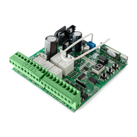
SSZ SSZ-RZ3 User manual

www.ssz-gmbh.de info@ssz-gmbh.de Thüringerstrasse 17, 46286 Dorsten1
MADE IN GERMANY
INSTALLATION AND SYSTEM DESCRIPTION
FOR SSZ CONTROL UNIT
TYPE SSZ-RZ3

www.ssz-gmbh.de info@ssz-gmbh.de Thüringerstrasse 17, 46286 Dorsten2
Thüringerstrasse 17, 46286 Dorsten
Tel: +49 236940 94
Fax: +49 23 69 - 2 15 97
Email: info@ssz-gmbh.de
Issue 2017, Version 1
This Operating Manual applies to control unit
• Type: SSZ- RZ3, Performance Level PL d (in system) Category
3, acc. to EN ISO 13849-1 to be connected to: SSZ-Safety Mats
and SSZ-Safety Rails and SSZ-Safety Bumpers.
Response time < 20 ms
Reset function - automatic/manual
Control unit identication is provided with the number, printed
on a hologram (on the housing).
For proper device identication, the Installer
should write down the ID number from the
hologram in the device identifying form!
Prior to installation, it is recommended to
read with understanding all the contents
of this Operating Manual, together with
operating manuals of particular pressure-
sensitive safeguarding products.
- SSZ safety mat instructions of use
- SSZ safety bumper instructions of use
- SSZ safety edge instructions of use

www.ssz-gmbh.de info@ssz-gmbh.de Thüringerstrasse 17, 46286 Dorsten3
TABLE OF CONTENT
TABLE OF CONTENT ........................3
ABOUT THIS OPERATING MANUAL ...........4
INTENDED USE ............................4
SAFETY RECOMMENDATIONS................5
CONTROL UNIT LABELLING .................6
MAINTAINED SAFETY LEVEL.................6
TECHNICAL PARAMETERS ...................7
SAFETY UNIT
FUNCTIONALITY TESTS . . . . . . . . . . . . . . . . . . . . . 9
CONNECTING OF SAFETY UNIT .............10
MOUNTING ..............................12
MAINTENANCE AND CONTROL
OF PROPER FUNCTIONALITY ...............12
STORAGE AND TRANSPORT ................14
UTILISATION .............................14
NOTES ...................................14
These instructions form is an essential part of the product.
These instructions contains basic information that must be noted when installing the system. It is important that the personnel famil-
iarize themselves with these instructions before installation and commissioning. The following documents from the purchaser also
apply in addition to these instructions:
• The drawing of the conguration (optional)
• The cable diagrams (optional)

www.ssz-gmbh.de info@ssz-gmbh.de Thüringerstrasse 17, 46286 Dorsten4
Keep the operating manual at accessible location during the
entire service life of the product. This operating manual shall
be passed onto any subsequent owners / users of the product.
Any updates to the contents of the operating manual, received
from the product manufacturer, shall immediately be included
in this operating manual.
The technical personnel shall be familiar with assembly and
mounting techniques, as well as with the functions of devices
and systems.
This operating manual is valid only for the product specied on
the title page. In addition to this operating manual, the following
documents shall be followed:
• structure drawings of machine / device, remaining at the
customer’s disposal (optional),
• a schematic drawing of connection
• an assembly drawing of devices with SSZ sensor(s) - see
Annex No. 1 to this operating manual.
This operating manual is a part of the product
The control unit is a part of the system:
SSZ pressure sensitive safety products + a
control unit. The system shall be connected
to a machine by properly trained technical
personnel only.
In no event shall the SSZ GmbH Company be
liable for any damages arising from or being
a consequence of the product usage not in
compliance with the operating manual.
The target group of this operating manual
includes the product end-user and properly
trained personnel (operators), authorised to
use the product.
Before use of the product, read thoroughly
this operating manual.
ABOUT THIS OPERATING MANUAL
SSZ-RZ3 control unit is intended to generate a safety-related sig-
nal for emergency stop of machines and other technical devices.
The control units may also be used to generate warning signals
of persons. The control unit is designed for analysis and control
of two-channel elements of in an electric circuit, including SSZ
safety edges, SSZ safety mats and SSZ safety bumpers.
In wires, including the voltage supply wire, constant monitoring
covers: electric energy ow direction, short-circuits and crossed
wires, in compliance with the constant current principle.
SSZ-RZ3 control units can be supplied either with 24 V AC/DC or
with 230 V AC.
In either case, the polarity of connected wires is not important.
INTENDED USE

www.ssz-gmbh.de info@ssz-gmbh.de Thüringerstrasse 17, 46286 Dorsten5
Supply voltage control shall be ensured. The supply voltage
must be equal to the voltage value on the rated plate.
REQUIRED SPACING
While performing assembly tasks in the electric cabinet, it is
necessary to maintain proper distance from heat sources.
PROTECTION FROM SUNLIGHT
The electric cabinet shall be protected from direct sunlight.
TERMINAL CURRENT LOAD
Terminal current load shall be observed.
PROTECTION OF RELAY CONTACTS
The risk of welding together: the relay contacts beyond the
connecting area shall be provided with an overcurrent protec-
tion with activation amperage equal to the maximal permitted
current of relay contact. Do not overload SSZ-RZ3 and SSZ-RZB
control units. The specied switching (load) current shall not
be exceeded.
IN CASE OF ANY FAILURE, SWITCH OFF THE UNIT!
SSZ-RZ3 control unit shall be switched o in case of any failure
or defects.
DO NOT USE THE CONTROL UNITS IN POTENTIALLY EXPLO-
SIVE (ATEX) ZONES
SSZ-RZ3 control unit can not be used in zones with explosion
hazards (ATEX zones).
THE RISK OF INJURY FROM ELECTRIC SHOCK!
Before and during the mounting works of SSZ-RZ3 control unit,
all the electric machines/devices to be connected must be
switched o from voltage supply.
OPERATION FAILURE DUE TO OVERHEATING
A pressure-sensitive product (SSZ safety mat, SSZ safety edge
or SSZ safety bumper) functions may be disturbed in result of
control unit overheating. A safety unit shall be mounted in en-
closures with IP54 as minimal protection index (e.g. in control
cabinets).
TERMINAL ASSIGNMENT
Terminal assignment shall be observed when connecting the
supply voltage
PROTECTION OF RELAY CONTACTS
Any changes shall be forbidden in control unit
setting or structure.
The machine shall not be switched on in
case of any hazard! Failure to respect these
recommendations may be hazardous to health
or even life-threatening!
The CE declaration of conformity is not valid
when devices or control units, other than SSZ,
are connected.
SAFETY RECOMMENDATIONS
THE SCOPE OF DELIVERY
1 x safety unit
An enclosure with an electronic module and plug-in connec-
tions
1 x operating manual
Immediately after delivery is received, it shall be checked for
completeness and visual status.
Danger of contact welding Relay output shall additionally be
external protected
DO NOT OVERLOAD CONTROL UNITS
It shall be ensured that contact current is not exceeded.
MAINTAINED REDUNDANCY
It shall be ensured that all connections are made within the
circuit or that another control unit.

www.ssz-gmbh.de info@ssz-gmbh.de Thüringerstrasse 17, 46286 Dorsten6
CONTROL UNIT LABELLING
MAINTAINED SAFETY LEVEL
SSZ-RZ3
The control units correspond to category 3, Performance Level
PLd - in compliance with EN ISO 13849-1.
NOTE: The control unit is a part of the system. SSZ a pressure-sen-
sitive device + a control unit, PLd is the highest safety level for
the entire system.
Any modications nor installation of any other devices in the sys-
tem is allowed. Only the SSZ control unit is an appropriate device
to control the SSZ pressure-sensitive product. Any replacements
of devices: of a control unit or of a pressure-sensitive product
by a solution of other manufacturer pose risks of failure or mal-
function of the entire system. Components may be replaced by
the end-user. Replacement tasks shall be undertaken by properly
trained technical personnel, with technical knowledge of machine/
device assembly and functions.
The end-user shall independently determine
the safety level of its application.
Safety category and level shall comply with
the category and level of safety assurance, as
determined by risk assessment.

www.ssz-gmbh.de info@ssz-gmbh.de Thüringerstrasse 17, 46286 Dorsten7
TECHNICAL PARAMETERS
SSZ-RZ3 TESTING BASICS EN ISO 13849-1/2, EN ISO 13856 1-3
Nominal supply voltage SSZ-RZ3 24 AC/DC; 230 V
Allowable voltage 10.6 VDC - 36 VDC or 8 VAC - 24 VAC; 230V
Max. current consumption 290mA@12VDC; 135mA@24VDC; 250mA@24VAC
Rated current 100mA@24VDC
Power consumption P1 2,1 W
Internal fuse 1500 mA
Power circut required fuse 2A
Working temperature range 0°C - +50°C
DIN Rail mount Yes
Max. resistance of the sensor element channel
1 and 2
250kOhm
Max. resistance dierence between the chan-
nels 1 und 2
20 %
Max. response time < 20ms
Performance Level acc. to EN ISO 13849-1 PL=d (Pl e)*
The service life 287 years
MTTFd in connection with SSZ-presure equip-
ment
74,1
DC (diagnostic coverage) 90%
CCF (common cause failure) 75
PFHd acc. to IEC/EN 62061 in connection with
SSZ-Pressure equipment
4.33E-8
The category acc. to IEC/EN 62061 SIL 2
Safety category acc. to EN ISO 13849-1:2016-02 3
Contact rating acc. to EN 60947-5-1 15 VAC (50/60Hz) - 3A 13 VDC - 3A
Min. switching current I1channel 9-10/11-12 5V/10 mA
Max. switching current I2channel 9-10/11-12 2 A
Mechanical endurance channel 9-10/11-12 >107
Electrical endurance channel 9-10/11-12 >3,6 x 10⁵(DC24V/1A)
Rated operational power 500mW
Reset automatic/manual
Storage temperature [°C] -10 - +50
Grade of protection acc. to IEC 60529:2003 IP30
Dimensions 112 x23x 99
Weight 180g

www.ssz-gmbh.de info@ssz-gmbh.de Thüringerstrasse 17, 46286 Dorsten8
*SSZ-RZ3 unit is a part of the system:
SSZ-pressure-sensitive device in connection
with SSZ-safety unit, therefore, despite
PL e category, obtained by SSZ-RZ3 unit,
the category has been decreased to PL d,
following the safety evaluation rules, and
this category shall be regarded valid because
whole system has to be considered.
Prior to the system connection, the installer is
obliged to read the operating manual of the
proper equipment in use:
- SSZ safety mat instructions of use
- SSZ safety edge instructions of use
- SSZ safety bumper instructions of use
SSZ-CONTROL UNITS, IN
COMBINATION WITH A PRESSURE-
SENSITIVE DEVICE (SAFETY MATES,
EDGES, BUMPERS) MAY OBTAIN THE
HIGHEST SAFETY LEVEL OF PL d.

www.ssz-gmbh.de info@ssz-gmbh.de Thüringerstrasse 17, 46286 Dorsten9
SAFETY UNIT
FUNCTIONALITY TESTS
• Disconnect sensors on terminals 3, 4, 5 and 6. Short terminals
3 and 5 with one wire and terminals 4 and 6 with another.
• After supply voltage is on red and the two green control LEDs
shall be illuminated and the output relays shall become active.
• If terminals 3 and 4 or 5 and 6 are shorted, then both channels
shall be inactivated: the green LEDs shall be o, while the
red LED shall be illuminated.(Simulation of the SSZ pressure
sensitive equipment activation)
• If the connection of terminals 3/5 is broken, the K1 relay shall
be inactivated. (Simulation of the broken cable).
• If the connection of terminals 4/6 is broken, the K2 relay shall
be inactivated. (Simulation of the broken cable).
• In manual reset, when terminals 3 and 5 and 4 and 6 are
shorted, only the red LED shall be illuminated. In order to
activate the K1 and K2 relays, press the reset button on
connected the RR terminals..
SAFETY UNIT TERMINALS
Safety unit terminal SSZ-RZ3 24V
AC/DC
SSZ-RZ3
230V AC
3SSZ-Sensor, terminal 3
4SSZ-Sensor, terminal 4
5SSZ-Sensor, terminal 5
6SSZ-Sensor, terminal 6
9Relays output
10 Relays output
11 Relays output
12 Relays output
RRESET button
RRESET button
Vh L (230V AC)
Vh N (230V AC)
VL +24V AC/DC
VL 0V
The SSZ-RZ3 control unit is factory set to operate
with automatic reset.

www.ssz-gmbh.de info@ssz-gmbh.de Thüringerstrasse 17, 46286 Dorsten10
CONNECTING OF SAFETY UNIT
If the RESET switch is in position “I“, the safety unit works in the
automatic reset mode. If the Reset switch is in position `0`the
SSZ-Control unit works in manual reset mode. In this case the
Reset button connected on Terminals RR shall be pressed and
released. To avoid any manipulation of the system the acknowl-
edgment follows af ter release of the before pressed Reset but ton.
The SSZ-RZ3B will be released after double acknowledgment of
the pressed before Reset button.
SCHEMATIC PRESENTATION OF THE SAFETY FUNCTION BE-
TWEEN SSZ-CONTROL UNIT AND THE MACHINE CONTROL
SYSTEM.
The output contacts of the control unit, serially connected, shall
be integrated with the machine emergency switch circuit. Unless
the pressure-sensitive device is activated, the relay contacts, i.e.,
also the emergency switch circuit, are closed. When the pres-
sure-sensitive device is activated, the relay contacts of the control
unit are opening, what stops the risk posing run of the machine.
Fig. Example of connection to machine control system with the
use of an SSZ-RZ3 control unit
Additional examples for each control units shall be available in
the operating instructions of a given control unit.
Reset options: automatic or via an external
button, closing the R-R circuit
Sensor terminals 3, 5, 4 and 6
Colours of cables 3 = green
5 = yellow
4 = brown
6 = white
Colours in case of
safety mats with
connector
3 = blue
5 = black
4 = brown
6 = white
Safety circuit 9-10 and 11-12
The safety of machine and proper
functionality of the safety pressure devices
depends on the correct installation of mutual
connections.

www.ssz-gmbh.de info@ssz-gmbh.de Thüringerstrasse 17, 46286 Dorsten11
SSZ-RZ3/RZ3B CONTROL UNIT CONNECTION TO MACHINE
OPERATING SYSTEM
Safe stop by external devices in manual reset
Safe stop by intern contacts in manual reset Safe machine stop by external devices in automatic reset
Safe stop by intern contacts in automatic reset

www.ssz-gmbh.de info@ssz-gmbh.de Thüringerstrasse 17, 46286 Dorsten12
MOUNTING
MAINTENANCE AND CONTROL OF
PROPER FUNCTIONALITY
Safety units of SSZ-RZ3 type are mounted on a DIN 35 mm rail,
see the drawing below.
The functional tests of control units shall be carried out daily.
• Prior to any maintenance works, disconnect the control unit
and the connected devices from the electric supply and
protect them against unintentional activation.
• Check if no voltage is present on any part or component.
• Clean the housing on the outside with a clean cloth.
AUTOMATIC RESET CONTROL FOR SSZ-RZ3 AND SSZ-RZ3B UNIT
The control unit is provided with an automatic reset function.
In a pressure-sensitive device is released, then K1 and K2 relays
will immediately return to their baseline position, switching the
control unit to standby mode.
Danger of electric shock!
Before re-start of the unit, check it for proper
functionality!
PROPER FUNCTIONALITY CONTROL FOR SSZ-RZ3 AND SSZ-
RZ3B UNIT: AUTOMATIC RESET CONTROL
1. Make sure that no SSZ pressure-sensitive device is activated.
• the “OK 3/5” and “4/6 OK” green LEDs are on
• The Relais contacts K1 & K2 are closed
2. Press the SSZ device
• the “OK 3/5” and “4/6 OK” green LEDs are o
• The Relais of K1 and K2 are open
• Release the pressure-sensitive device (do not press)
• the “OK 3/5” and “4/6 OK” green LEDs are on
• The relais contacts K1 and K2 are closed

www.ssz-gmbh.de info@ssz-gmbh.de Thüringerstrasse 17, 46286 Dorsten13
Manual reset control for SSZ-RZ3 unit
1. Press the SSZ-pressure-sensitive device
2. Make sure that no one of the SSZ pressure sensitive devices
is pressed
• The green LED`s “OK 3/5” and “4/6 OK” are o
• The relais contacts of the channel K1 & K2 are opened
3. Press the reset button
• The “OK 3/5” and “4/6 OK” green LEDs are on
• The relais contacts of the channel K1 & K2 are closed
4. Press the SSZ pressure-sensitive device
• The “OK 3/5” and “4/6 OK” green LEDs are switch o
• The relais contact of the channel K1 & K 2 are opened
5. Unlock the pressure-sensitive device
• The “OK 3/5” and “4/6 OK” green LEDs are switched o
• The relais of the contacts channel K1 & K2 are opened
6. Press the reset button, while the pressure-sensitive device
should not be pressed
• The “OK 3/5” and “4/6 OK” green LEDs are switched on
• The relais contacts of the channel K1 & K2 are closed
• The SSZ-pressure-sensitive device is unlocked and ready
for operation
Do not switch on the machine as long as there
is any risk!
Periodical inspections of the control unit should be carried out
at least twice a month, while the functionality of signalling lights
– LEDs – should be a subject of daily control. The frequency of
the inspections should be estimated appropriate to the safety
function activations
The SSZ-control unit check shall include:
• Visual check of the housing for possible damages.
• Exclusion of possible manipulations. The SSZ hologram shall
remain intact.
• Operation and functionality check executed acc. to this
Operation Manual.
• Checking the correctness of the installation in the electric box.
• Ensuring the correctness of connection to machine or device
After completing the assembly and function requirements the
system may be approved for use, according to the applicable
standards and regulations of the country of use.
The user may replace parts, using
exclusively their equivalents approved by
the manufacturer! Any modications or
installations of other components / devices in
the system shall be prohibited. The SSZ control
unit shall be the only device suitable for control
of SSZ sensitive devices. Replacing SSZ control
unit or pressure-sensitive devices by products
of other vendors poses a risk of functionality
failure or total collapse for the entire system!
No spare parts for the above-mentioned
system. In case of any failure, replacement
parts shall be sought from the manufacturer,
including the control unit, the cable, the
aluminium prole or the pressure-sensitive
device.
In order to ensure proper functionality
of a pressure-sensitive protective device,
as well as its installation, adhering to the
requirements of EN-ISO 13849-1-2 and EN ISO
13856-1-3 : 2013-1, the technical personnel
shall be familiar with assembly techniques,
as well as with gear and systems, supported
by training at the SSZ-GmbH Company or at
an agency, designated for the purpose by the
manufacturer.
In case of any technical problems, it is recommended to contact
the manufacturer or any responsible agency, representing the
manufacturer at a given country. See the manufacturer’s home-
page www.ssz-gmbh.de for the actual list of representatives.
Acceptance procedure
1.Pressure-sensitive device assembly and functionality check
acc. to the requirements in the Operation Manual of the chosen
SSZ pressure sensitive device .
2.Checking for correct cabling from the control unit to the SSZ
pressure sensitive device; a particular attention shall be paid to
redundancy preservation in the system!
3.Checking of the safety function– acc. to the safety documen-
tation.
4.Measurement of the entire system’s response time and “full
time stop”, as well as functionalit y(lock or release) check, caused
by the activation of an SSZ pressure-sensitive device. The results
should be compared to the specication requirements. All results
should be written into the documentation of the machine.
5.A special attention shall be paid to the signalling system in the
SSZ control unit (one red and two green LEDs), indicating either
normal operation or failure of the system!

www.ssz-gmbh.de info@ssz-gmbh.de Thüringerstrasse 17, 46286 Dorsten14
The applied prevention measures against systematic defects
(EN ISO 13849-1: 2015))
• The design of the devices ensures protection in case of sup-
ply voltage loss. The output relays become disconnected,
i.e., the electric circuit in open on the output relay contacts.
• In the supplying branches of measurement circuits, integrated,
voltage stabilisers are applied which, together with capacitive
lters, considerably protec t against input voltage variations.
• The input resistive measurement system has been designed
to eliminate as much as possible errors, resulting from un-
stable supply voltage.
• The applied output relays, designed for use in safety devices,
are subject of internal control.
• The design conguration of SSZ safety units has for years
been used in thousands of applications and is also used in
other, manufactured by us devices.
• Control unit SSZ-RZ3 has been designed in line with the
EU’s engineering pattern and checked and approved with
regards to electromagnetic compatibility, ventilation, cooling
and vibrations.
• The SSZ-GmbH Company has for more than 25 years been
carrying out internal quality control in its full scope, i.e.,
including particular elements and their documentation.
• The same team of qualied employees participates in the
production process.
• The parts and components in the devices originate from prov-
en, recognised manufacturers with appropriate certicates.
• The Company enjoys a more than 25-year tradition and
experience, represented all over the world, while in some
European countries, SSZ products are market leaders.
If none of the LEDs is active, the supply of the control unit should
be checked. If the supply connection to the control unit is cor-
rect, while its functionality still fails, it is necessary to contact
the manufacturer.
The same acceptance procedure shall be valid when particular,
individual components are replaced (either of SSZ pressure-sen-
sitive device or a replacement of the SSZ control unit)
The installer shall be obliged to ll in an identication form of
an installed device. In order to ensure a correct identication,
please enter in the form, the number from the hologram on the
pressure-sensitive device and on the SSZ control unit.
The system does not have an auto-check
function. According to the level of safety
assurance- PLd , the system in the standby
mode is controlled by the unit.

www.ssz-gmbh.de info@ssz-gmbh.de Thüringerstrasse 17, 46286 Dorsten15
STORAGE AND TRANSPORT
UTILISATION
NOTES
SSZ-RZ3 and SSZ-RZ3B control units shall be stored and trans-
ported in their original, manufacturer’s packaging, protecting
them from damage. The units are individually packed in carton
boxes, together with operating manuals.
The devices, manufactured by the SSZ GmbH Company, are pro-
fessional electronic solutions, designed exclusively for industrial
applications (so called, B2B devices). Unlike the commonly used
household utilities (B2C), B2B devices must not be disposed to-
The units shall be stored at indoor, dry premises, the relative
humidit y of which shall not exceed 80%. The ambient air temper-
ature shall not exceed the range from -10°C to 70°C. Protection
grade of control unit enclosure against external factors: IP 30
gether with municipal waste. When the ser vice life of a B2B device
expires, it can be returned to the SSZ GmbH for proper utilisation.
Safety units are only a part of safety system
- design and construction of a safety system
shall be based on the rules and provisions,
contained in standards and in the machine
directive.
Before any unsafe machine task, the safety
system functionality shall be checked, if
possible. The functionality check involves ssz
safety unit activation and conrmation that a
dangerous machine run has been stopped.
Regardless of the circumstances, the
occupational safety rules, as well as other
appropriate regulations shall be adhered to.
Failure to do so may pose hazards for health
and life.
If a defect/failure occurs, such a unit shall be
returned to the manufacturer for repair.
All electric connections shall properly be
tightened and checked. Periodical checks of
electric terminals shall be scheduled.
Ssz units shall be mounted exclusively in
electric cabinets. The required protection
degree shall be observed.
Opening the SSZ – control unit box may
lead to the loss of the system safety. Under
no circumstances shall the devices be
opened. Any hologram breach shall make the
guarantee void.
All external cable feeds shall be protected
against excessive loads and led in insulating
sleeves.
Rated load values on outer contacts shall not
be exceeded.

www.ssz-gmbh.de info@ssz-gmbh.de Thüringerstrasse 17, 46286 Dorsten16
Thüringerstrasse 17, 46286 Dorsten-Wulfen
+ 49 2369/4094
+ 49 2369/21597
info@ssz-gmbh.de
ssz-gmbh.de
ALL RIGHTS RESERVED
Version 2017
A:
T:
F:
E:
W:
Table of contents
Other SSZ Control Unit manuals

