manuals.online logo
Brands
  1. Home
  2. •
  3. Brands
  4. •
  5. AEG
  6. •
  7. Ventilation Hood
  8. •
  9. AEG 125 D User manual

AEG 125 D User manual

Other manuals for 125 D

3

Other AEG Ventilation Hood manuals

AEG DK 9660 Assembly instructions

AEG

AEG DK 9660 Assembly instructions

AEG 820 D User manual

AEG

AEG 820 D User manual

AEG 330 D User manual

AEG

AEG 330 D User manual

AEG DI 8820 User manual

AEG

AEG DI 8820 User manual

AEG 835 D User manual

AEG

AEG 835 D User manual

AEG EFP60924OW User manual

AEG

AEG EFP60924OW User manual

AEG X56263MD20 User manual

AEG

AEG X56263MD20 User manual

AEG 8160 D User manual

AEG

AEG 8160 D User manual

AEG DPE5660G User manual

AEG

AEG DPE5660G User manual

AEG FM2500DD-A User manual

AEG

AEG FM2500DD-A User manual

AEG 222 D User manual

AEG

AEG 222 D User manual

AEG DCE5260HM User manual

AEG

AEG DCE5260HM User manual

AEG 341 D Specification sheet

AEG

AEG 341 D Specification sheet

AEG DDE5980G User manual

AEG

AEG DDE5980G User manual

AEG ADX6350AM User manual

AEG

AEG ADX6350AM User manual

AEG DTB3953M User manual

AEG

AEG DTB3953M User manual

AEG CHDD 8509 Specification sheet

AEG

AEG CHDD 8509 Specification sheet

AEG DK 9160-9190 User manual

AEG

AEG DK 9160-9190 User manual

AEG COOKER HOOD DF 6160 User manual

AEG

AEG COOKER HOOD DF 6160 User manual

AEG 825 D User manual

AEG

AEG 825 D User manual

AEG X94484MV10 User manual

AEG

AEG X94484MV10 User manual

AEG DEI 60 PL 2 User manual

AEG

AEG DEI 60 PL 2 User manual

AEG DCK5970HM User manual

AEG

AEG DCK5970HM User manual

AEG DH 1690 User manual

AEG

AEG DH 1690 User manual

Popular Ventilation Hood manuals by other brands

Gorenje S3 IHGC963S4X manual

Gorenje

Gorenje S3 IHGC963S4X manual

KOBE ISX2136SQB-1 Installation instructions and operation manual

KOBE

KOBE ISX2136SQB-1 Installation instructions and operation manual

U.S. Products ADVANTAGE-100H Information & operating instructions

U.S. Products

U.S. Products ADVANTAGE-100H Information & operating instructions

Kuppersberg DUDL 4 LX Technical Passport

Kuppersberg

Kuppersberg DUDL 4 LX Technical Passport

Framtid HW280 manual

Framtid

Framtid HW280 manual

Thermador HGEW 36 FS installation manual

Thermador

Thermador HGEW 36 FS installation manual

Electrolux LFT769X user manual

Electrolux

Electrolux LFT769X user manual

Broan B5836SS manual

Broan

Broan B5836SS manual

Heinner HDCH-6060RGBK quick start guide

Heinner

Heinner HDCH-6060RGBK quick start guide

Baumatic AS35SS instruction manual

Baumatic

Baumatic AS35SS instruction manual

Franke FTF 604 XS V2 Instructions for use and installation

Franke

Franke FTF 604 XS V2 Instructions for use and installation

Best UCB3I30SBW installation instructions

Best

Best UCB3I30SBW installation instructions

Gram EFU 503-90 X instruction manual

Gram

Gram EFU 503-90 X instruction manual

CIARRA CBCS6803 Installation and user manual

CIARRA

CIARRA CBCS6803 Installation and user manual

sauter SHG501 Instructions for installation and use

sauter

sauter SHG501 Instructions for installation and use

Franke 392-17 User instructions

Franke

Franke 392-17 User instructions

FALMEC Polar Black 35 Instruction booklet

FALMEC

FALMEC Polar Black 35 Instruction booklet

Remus 7783 089518L Installation instruction

Remus

Remus 7783 089518L Installation instruction

manuals.online logo
manuals.online logoBrands
  • About & Mission
  • Contact us
  • Privacy Policy
  • Terms and Conditions

Copyright 2025 Manuals.Online. All Rights Reserved.

125 D
ExtractorHood
InstallationandOperatingInstructions
2
Contents
Introduction 3
Extraction mode 3
Recirculation mode 4
Electrical connection for UK 5
Technical details 6
Installation 7
Safety warnings for kitchen unit installer 7
Wall mounting 9
Hood operation 11
Safety warnings for user 12
Maintenance and care 13
Opening the grid 13
Grease filter 13
Carbon filter 14
Changing the light bulb 15
Cleaning 15
Accessories 16
Something not working 17
Service & Spare Parts 18
Printed on recycled paper.
AEG  putting words into action.
3
2
Introduction
Extraction mode
●The hood is supplied as an extractor unit and can also be used as a
filtered function (recirculation) by fitting activated carbon filters
(available as an accessory).
●The unit features two outlet holes, one of which Ais located on the
top of the unit while the other Bis located on the rear.
●To connect up the hose, you should first fit the bayonet-mounting
flange C(Ø 100-120 mm) on the outlet required (if using the top
outlet, fix the flange in place using the screw supplied as shown in
Fig. 1).
Close off the unused hole using the bayonet fitting caps D.
●Important! To use the back hole B, remove switch Ffrom the
top hole.  Fig 2.
1
C
A
B
D
D
A
B
C
4
●Move the lever Lto position A Fig. 3.
●When connecting the hood using a telescopic wall pipe,
you should use a non-inflammable outlet hose ABS 120
(120 mm Ø)
E-Nr. 942 118 611 from our range of special accessories.
Recirculation mode
●The air is filtered and recirculated through the front grid.
●Move the lever Lto position F  Fig. 3.
You will need an original KFF activated carbon filter. (See
accessories).
Summer/Winter Hood Conversion
●To avoid excessive heat loss during the winter months, we
recommend that the hood be converted from extraction mode
to recirculation.
●In order to convert the hood, a charcoal filter (available as an
accessory) is required. Follow the instructions for operating the
hood to recycle air.
●When the temperature outdoors becomes more mild (spring),
the filter can be removed and the hood converted once again to
extraction. Please consult the assembly instructions for operating
the hood in extraction mode.
3
LL
5
Electrical connection for the UK
Appliances with 2 wires
WARNING: DOUBLE INSULATED - DO NOT EARTH
The appliance must be connected to fixed wiring with a double
pole switched fused spur outlet with or without pilot lamp.
We strongly recommend the appliance to be connected only by a
qualified electrician who is a member of the NICEIC who will
comply with the IEE and any local regulations.
NOTE:
The terminology DOUBLE POLE means that both the live and the
neutral supplies are switched and disconnected at the same time.
The terminations labelled SUPPLY are for the connection for the
internal house wiring and the terminations labelled LOAD are for the
appliance.
IMPORTANT
The wires of the mains lead supplied with this appliance are
coloured in accordance with the following code:
Blue-Neutral
Brown-Live
As the colours of the flexible cord of this appliance may not
correspond with the coloured markings identifying the termi-
nals in the plug, proceed as follows: The wire which is coloured
brown must be connected to the terminal which is marked
with the letter L or coloured red.
The wire which is coloured blue must be connected to the
terminal which is marked with the letter N or coloured black.
N
LOAD
L
SUPPLY
L
LOAD
N
SUPPLY
DP 13A, 250V
BLUE
(NEUTRAL) BROWN
(LIVE)
FUSE ON
6
Technical details
Dimensions
Height x Width x Depth (in cm) 69-113 x 59.9 x 51
Weight
Net: 11,5 kg
Gross: 12,6 kg
Maximum absorbed power: 205 W
Motor absorption 1 x 125 W
Lighting: 2 x 40 W
Length of the cable: 110 cm
Fan powers (speed), speed in compliance with DIN 44971
Extraction mode
1 115 m3/h
2 152 m3/h
3 210 m3/h
Recirculation mode
1 110 m3/h
2 129 m3/h
3 145 m3/h
Flange:100-120 mm Ø
7
Installation
Safety warnings for kitchen unit installer
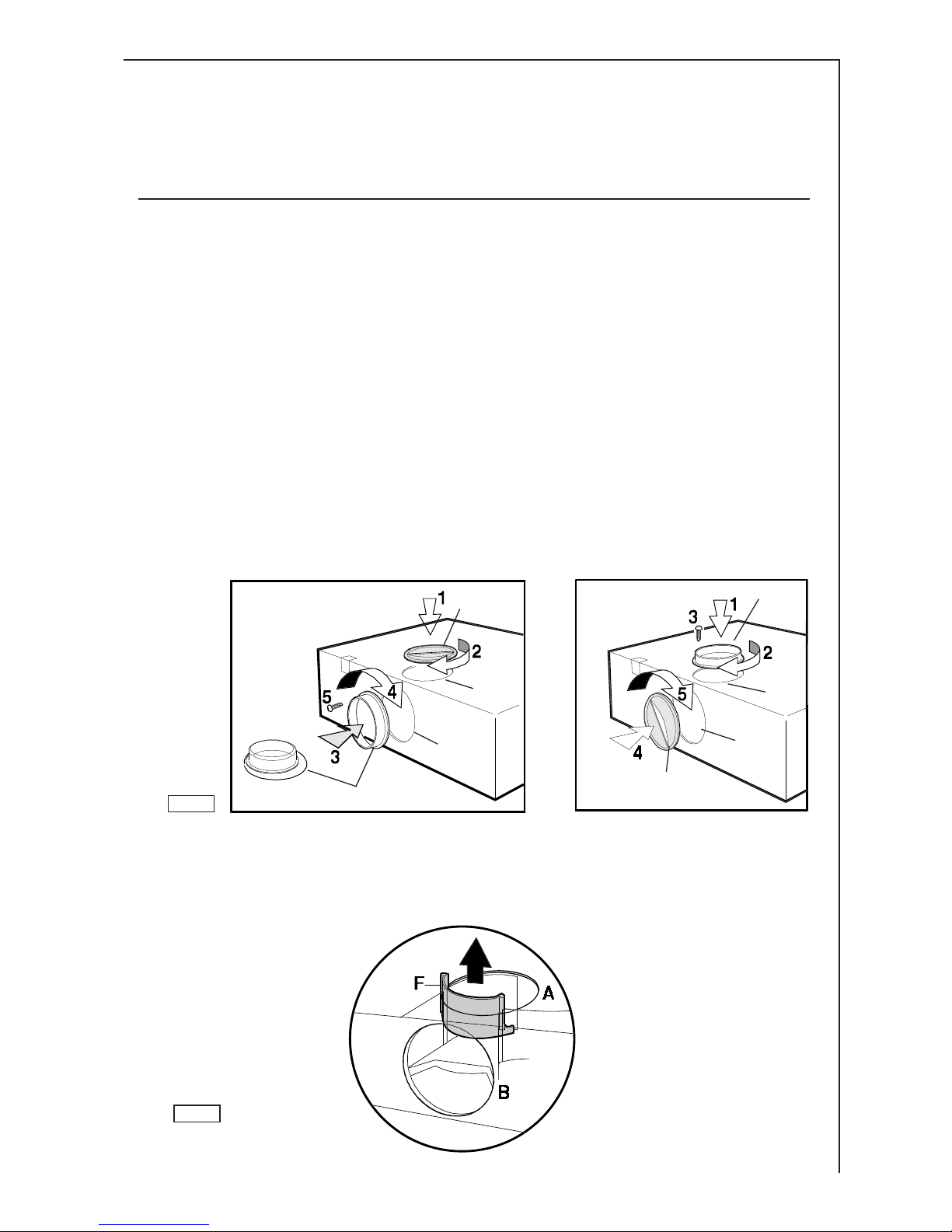
●When used as an extractor unit, the hood must be fitted with a
100 or120mm diameter hose.
●If the fumes must be forced out through the wall, you must
obtain a MKZ sizable wall exhaust pipe (with external exhaust and
air intake), E-Nr.- 610 899 004 (Ø 120 mm) which is one of our
optional parts.
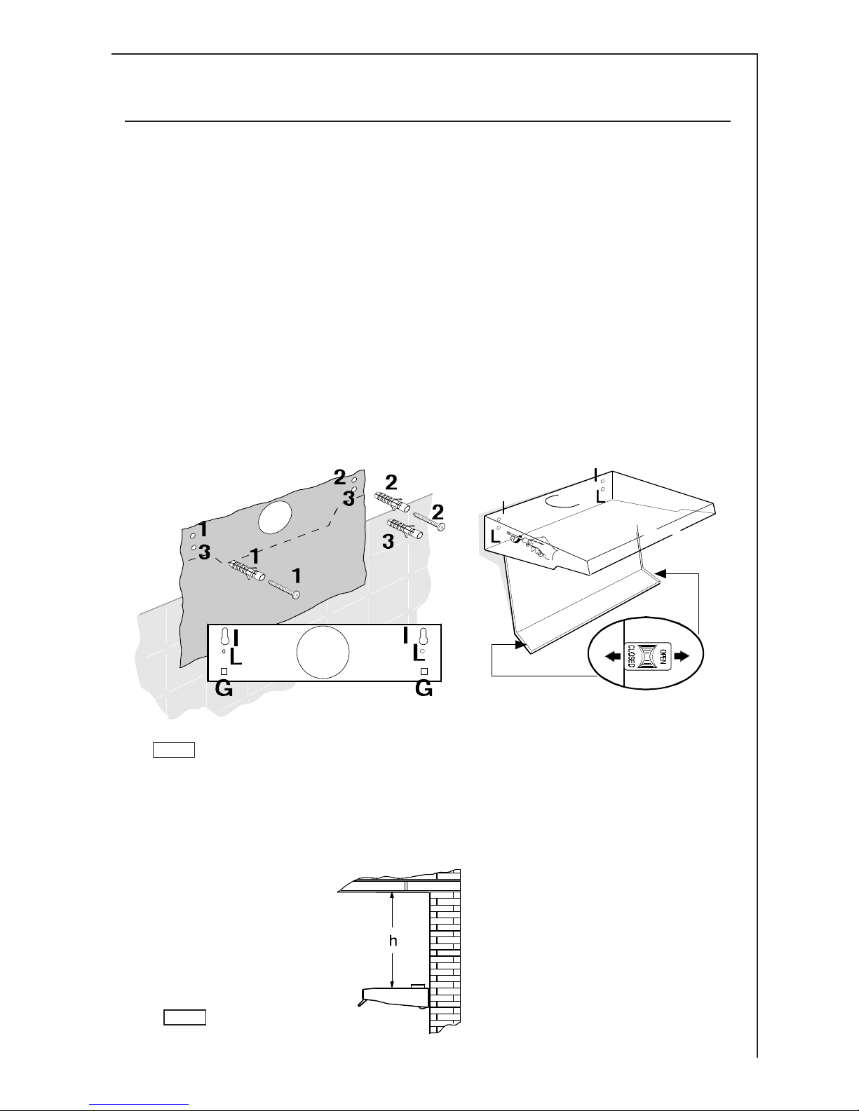
●When installing the hood, make sure you respect the fol-
lowing minimum distance from the top edge of the cooking
hob/ring surfaces:
Electrical 650 mm
Gas hob 700 mm
Electric cooker 685 mm
Gas cooker 787 mm
●The hood cannot be connected to flues of other appliances that
run on energy sources other than electricity.
●The air outlet must not be connected to chimney flues or com-
bustion gas ducts. The air outlet must under no circumstances be
connected to ventilation ducts for rooms in which fuel-burning
appliances are installed.
●It is advisable to apply for authorization from the relevant
controlling authority when connecting the outlet to an unused
chimney flue or combustion gas duct.
The air outlet installation must comply with the regulations laid
down by the relevant authorities.
●When the unit is used in its extractor version, a sufficiently large
ventilation hole must be provided, with dimensions that are
approximately the same as the outlet hole.
●National and regional building regulations impose a number of
restrictions on using hoods and fuel-burning appliances connected
to a chimney, such as coal or oil room-heaters and gas fires, in
the same room.
8
●Regulations on fuel-burning systems specify a maximum
depression of 0.04 bar in such rooms.
●Hoods can only be used safely with appliances connected to a
chimney if the room and/or flat (air/environment combination) is
ventilated from outside using a suitable ventilation hole approxi-
mately 500-600 cm2 to avoid the possibility of a depression
being created during operation of the hood.
If you have any doubts, contact the relevant controlling authority
or building inspectors office.
●Since the rule for rooms with fuel burning appliances is outlet
hole of the same size as the ventilation hole, a hole of 500-600
cm2, which is to say a larger hole, could reduce the performance
of the extractor hood.
●If the hood is used in its filtering function, it will operate simply
and safely in the above conditions without the need for any of the
aforementioned measures.
●When the hood is used in its extractor function, the following
rules must be followed to obtain optimal operation:
 short and straight outlet hose
 keep bends in outlet hose to a minimum
 never install the hoses with an acute angle, they must
always follow a gentle curve only
 keep the hose as large as possible (120 mm Ø min.).
●Failure to observe these basic rules will drastically reduce the
performance and increase the noise levels of the extractor hood.
9
Wall mounting
●Fix the drilling template to the wall.
●Make 3 Ø 8mm holes in the wall 2 at points I, 1 as desired at
points L.
●Insert the three Ø 8mm expansion plugs into the wall.
●Insert 2 5x45 screws at points Ibut do not tighten them
completely.
●Adjust the unit so that it is positioned at a right angle to the wall
by turning the two support screws G.
●Fit the hood into holes I, tighten the 2 screws.
●From inside the hood, insert the third 5x45 screw into hole L. 
Fig. 4.
●Measure the height between the upper side of the body of the
cooker hood and the ceiling (fig. 5).
5
4
10
●Set the chimney according to the measured height and stop its
run with the two fixing screws 2,9x6,5 mm supplied (fig. 6).
●Fix the chimney to the aesthetic top with two screws 2,9x6,5
mm supplied (fig. 7).
●From the inside of the hood, fix the aesthetic top with four screws
M3x6 supplied (Two each side)(fig. 8).
●Fix the upper bracket to the wall, close to the ceiling,
perpendicularly to the outlet hole of the hood with 2 screws
5x45 mm (fig. 8).
●Fix the chimney to the bracket with two screws 2,9x6,5 mm
(fig. 8).
67
8