AEM 21-683 User manual

Equipped with AEM®Dryflow™ Filter
No Oil Required!
INSTALLATION INSTRUCTIONS
PART NUMBER:21-683
2010 HONDA Accord V6-3.5L SEE * NOTE
2008-2009 HONDA Accord V6-3.5L C.A.R.B. E.O. # D-670
Excludes 2009 MY LEV II SULEV 8HNXV03.5BMC and 2008 MY LEV II SULEV 9HNXV03.5EC3
model year vehicles.
2
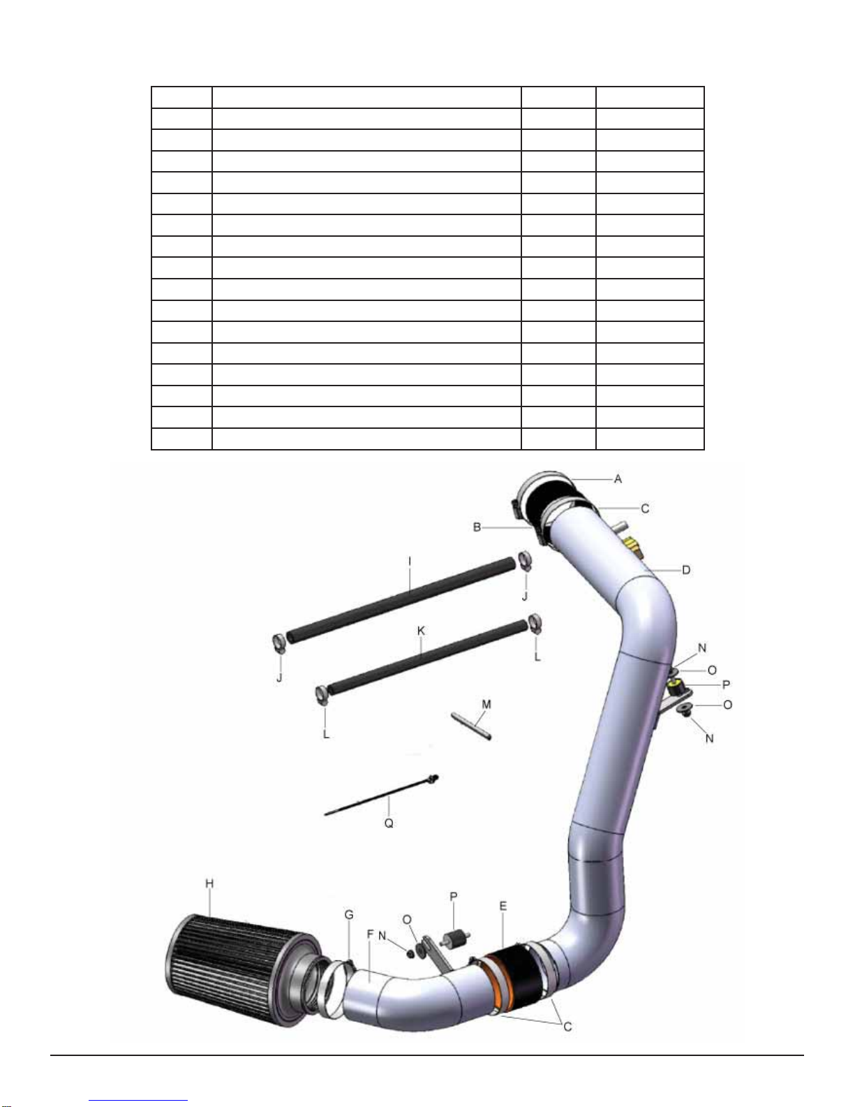
Description Qty. Part Number
PARTS LIST
A 1/2” Bnd. Hose Clamp, 2.31-3.25” 1 9444
B Hose, Adapter 3.25/3.00 X 2.25” 1 5-323
C 1/2” Bnd. Hose Clamp,2.90”-3.75” 3 9452
D Upper Pipe 1 2-6831
E Hose, Silicone 3.25 X 2.0” 1 5-326
F Lower Pipe 1 2-6832
G 1/2” Bnd. Hose Clamp, 3.15”-4.00” 1 9456
H Air Filter Assy 3.25 X 7” Dry Ele. 1 21-2113DK
I Hose; 1/2”ID X 16”L 1 5-5016
J Hose Clamp, 1” 2 99024.032
K Hose; 5/16ID X 14”L 1 5-2014
L Hose Clamp, 3/4” 2 4093-5
M Rubber Edge Trim 5” 1 8-3005
N Nut, M6 Hex Serrated 3 444.460.04
O Washer, 6mm Soft Mount 3 08160
P Mount, Rubber 1” X 6mm 2 1228599
Q Zip Tie, 8” Tree Push-Mnt. 1 1-127
3
1. Preparing Vehicle
a.Make sure vehicle is parked on level surface.
b.Set parking brake.
c. If engine has run in the past two hours, let it cool down.
d.Disconnect negative battery terminal.
e.Do not discard stock components after removal of the factory system.
2. Removal of stock system
Read and understand these instructions BEFORE attempting to install this product. Failure to
follow installation instructions and not using the provided hardware may damage the intake
tube, throttle body and engine.
The AEM®intake system is a performance product that can be used safely during mild weather
conditions. During harsh and inclement weather conditions, you must return your vehicle to
stock OEM air box and intake tract configuration. Failure to follow these instructions will void
your warranty.
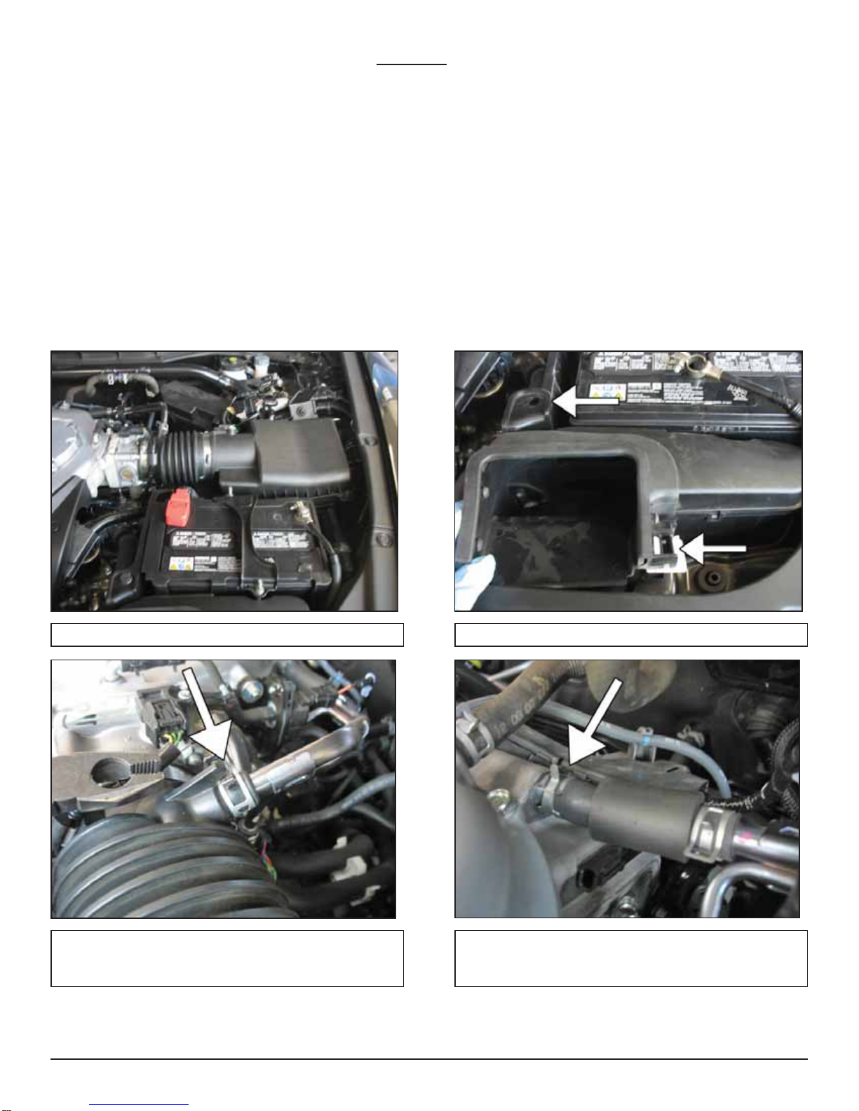
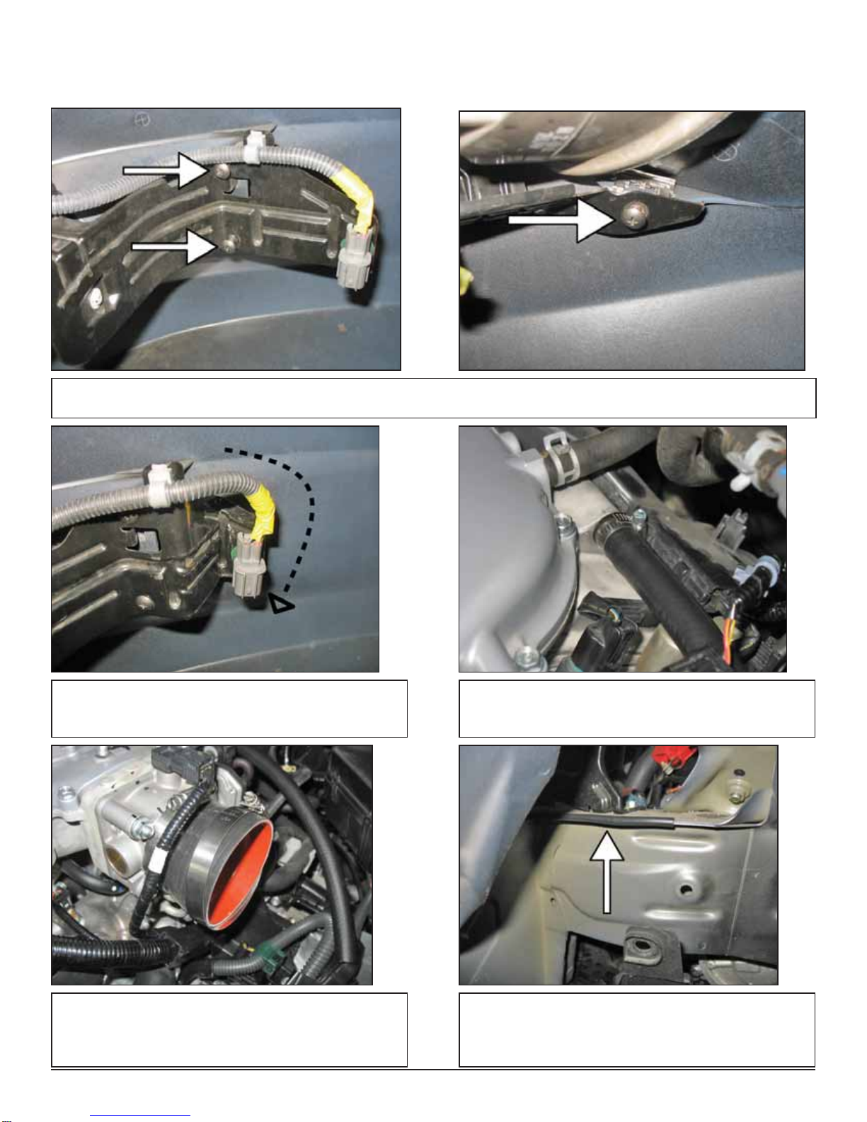
b. Remove the front inlet duct located near the battery.a. Stock airbox system installed.
c. Remove the PCV line from the inlet tube by com-
pressing the spring clip with a pair of pliers, while
twisting the tube out of the housing.
d. Repeat the same process of step 2c, but on the
crankcase side.

4
e. CAUTION: Ensure the engine is completely cool before removing the coolant hose, or hot coolant will escape
from the cooling system and cause injury or damage. Be sure to capture any lost coolant in a clean container.
Remove the corresponding coolant line that is attached to the PCV line and replace with the provided 5/16” hose
(5-2014). Secure with the provided hose clamps (4093-5). There are two ports for the coolant as shown in the middle
photo. Use caution, small amounts of coolant will spill out. Be sure to capture any lost coolant in a clean container. Also
use a rag to cover any areas where coolant may leak. Be sure to clean up any spilled coolant. After the new hose
(5-2014) is installed and secured, replace any coolant recovered during the hose removal by replenishing the recovery
tank.
f. Remove the battery by removing the battery tie
down and disconnecting the positive terminal. g. Loosen the hose clamp securing the inlet tube to
the throttle body. Also, remove the wiring harness
from the inlet tube.
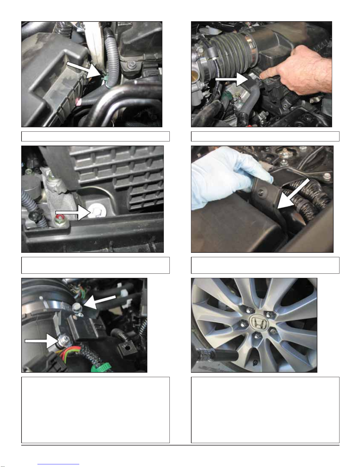
h. Unplug the wire harness connection from the MAF
sensor. i. Remove the green clip securing the wire harness to
the airbox panel.
5
j. Remove the retaining clip indicated in the picture. k. Remove the retaining clip on the battery.
l. Remove the 10mm bolt securing the airbox near the
bottom of the airbox. m. Push the airbox panel unit out from the dowel and
set aside.
n. Remove the MAF sensor from the airbox with a
Philips screwdriver. o. Raise the front of the vehicle with a jack. Refer to
your owner’s manual for proper jack and jack stand
placement to properly support vehicle. Support your
vehicle using properly rated jack stands before wheel
removal or while working under the vehicle.
NEVER WORK UNDER A VEHICLE WITHOUT US-
ING JACK STANDS.
Remove the driver-side front wheel with a 19mm
socket.

6
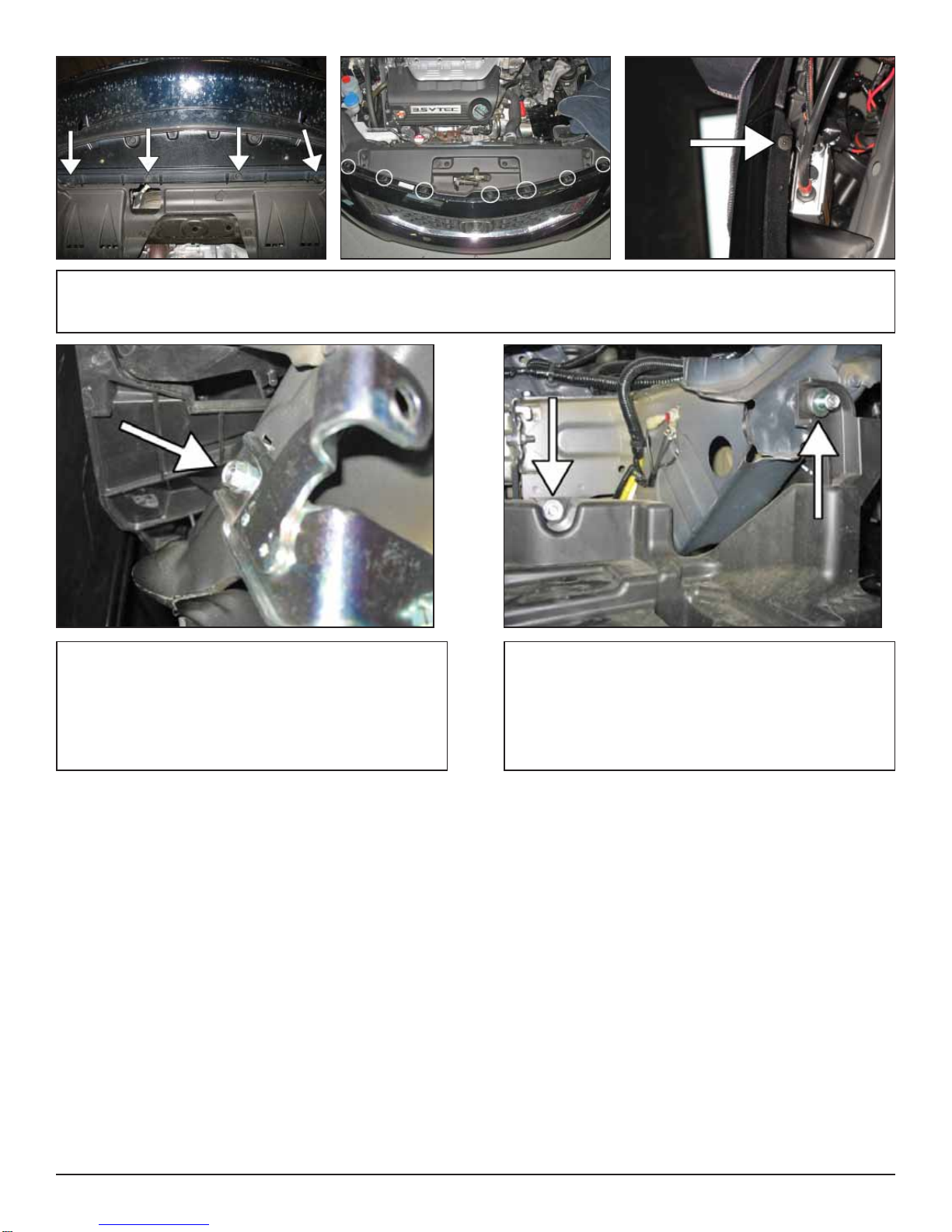
p. Remove the side clips holding the wheel well lining
as shown. q. Remove the bottom clips holding the bottom plastic
tray.
r. Push back the fender liner as shown in the picture. s. Remove the plastic battery tray and remove the two
bolts as shown.
t. Locate and remove the two bolts on the side of the
vehicle’s frame. u. Underneath the battery bracket, remove the 10mm
bolt that holds the air induction pipe to the battery
bracket.
7
v. Remove the front bumper by removing the side and bottom clips as indicated. Please do not forget to remove the
Phillips screw (picture on the far right) from both the left and right side of the vehicle. If the vehicle is equipped with fog
lights, unplug them before removing the bumper.
w. Locate and remove the 10mm bolt holding the re-
mainder of the airbox system to the chassis.
If your vehicle has an automatic transmission,
please proceed to step x. Manual transmission ve-
hicles, proceed to section 3 “Installation of AEM®
intake system”.
x. Remove two 10mm bolts as indicated.
8
3. Installation of AEM®intake system.
a.When installing the intake system, do not completely tighten the hose clamps or mounting hardware until instructed
to do so.
b. Locate the driver side fog light bracket. It is clipped onto the front bumper. Remove the three mounting screws shown
in the photos.
c. With the foglight removed from the bumper, bend
the fog light bracket in the orientation shown in the
diagram.
d. Insert the ½” hose (5-5016) onto the crankcase,
securing with the 1” hose clamp. Leave the other end
open for now.
e. Place the reducer coupler (5-323) onto the throttle
body with the smaller side over the throttle body. Se-
cure the smaller side of the coupler with the provided
hose clamp (9444).
f. Apply the rubber edge trim onto the frame rail as
indicated.

9
g. Insert one of the 1” rubber mounts (1228599) into
the indicated area. Secure with a supplied 6mm
fender washer and serrated nuts.
h. Insert the upper inlet pipe (2-6831) into the previ-
ously installed reducer coupler on the throttle body.
The end of the inlet pipe closest to the PCV nipple and
MAF adapter should install into the throttle body cou-
pler. Secure in place with a hose clamp (9452).
i. Slide the upper inlet pipe’s bracket onto the previ-
ously installed rubber mount; loosely secure with a
6mm washer and nut.
j. Install the MAF sensor with the factory hardware;
connect the wire harness to the MAF sensor.
k. Connect the other end of the ½” hose to the upper
inlet pipe’s nipple and secure with the provided hose
clamp (99024.032).
10
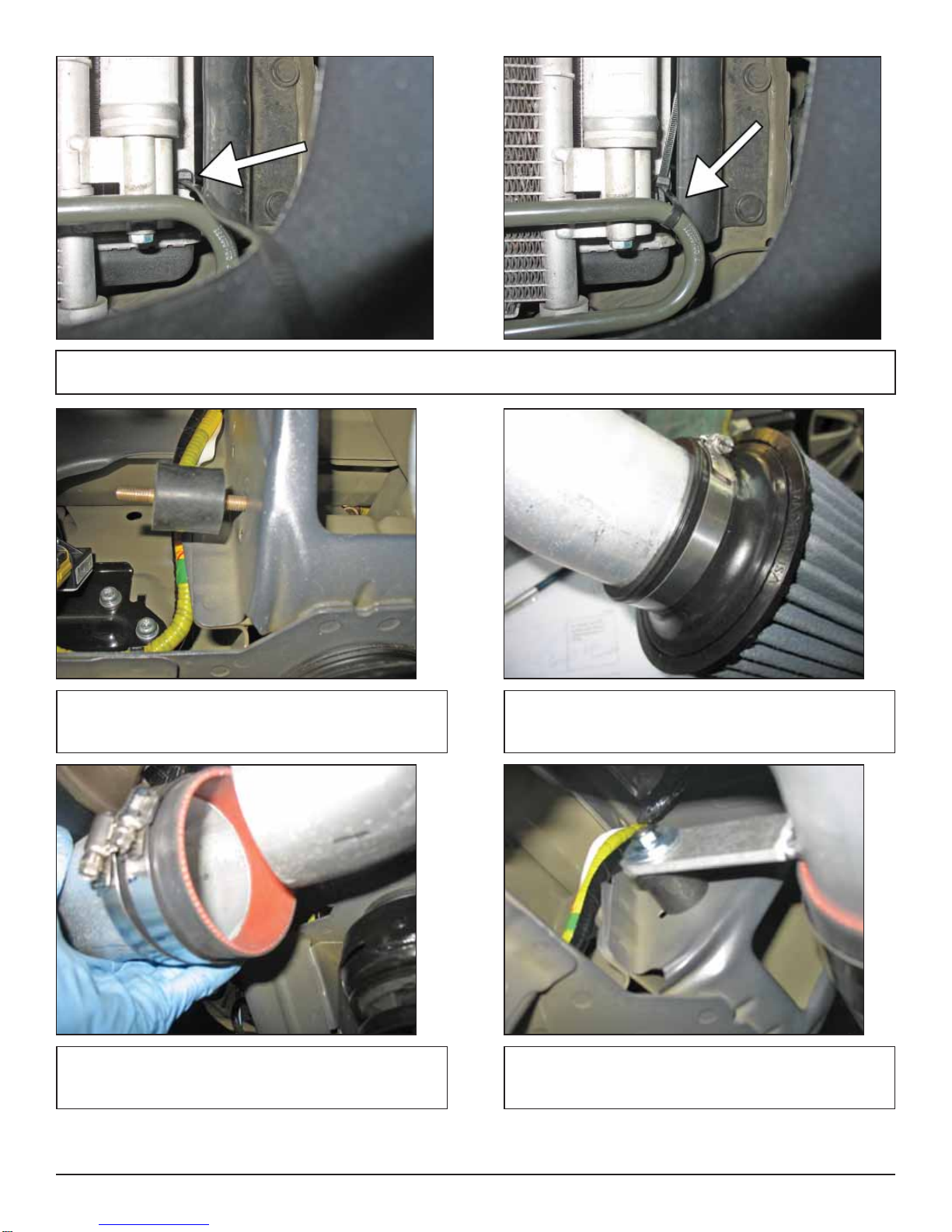
l. Insert the tab of the zip-tie (1-127) into the hole on the radiator support. Wrap the zip-tie around the condenser coil
and tighten, so the coil is pulled inward approximately 10mm.
m. Insert the other rubber mount (1228599) into the
indicated area. n. Install the air filter element onto the non-bracket
side of the lower inlet pipe (2-6832). Secure in place
with the provided hose clamp (9456).
o. Connect the lower inlet pipe to the upper inlet pipe
with the straight coupler (5-326) and a (9452) hose
clamp.
p. Slide the lower inlet pipe’s bracket onto the rubber
mount that was installed in step 3m. Secure the rubber
mount with the provided 6mm fender washer and nut.
11
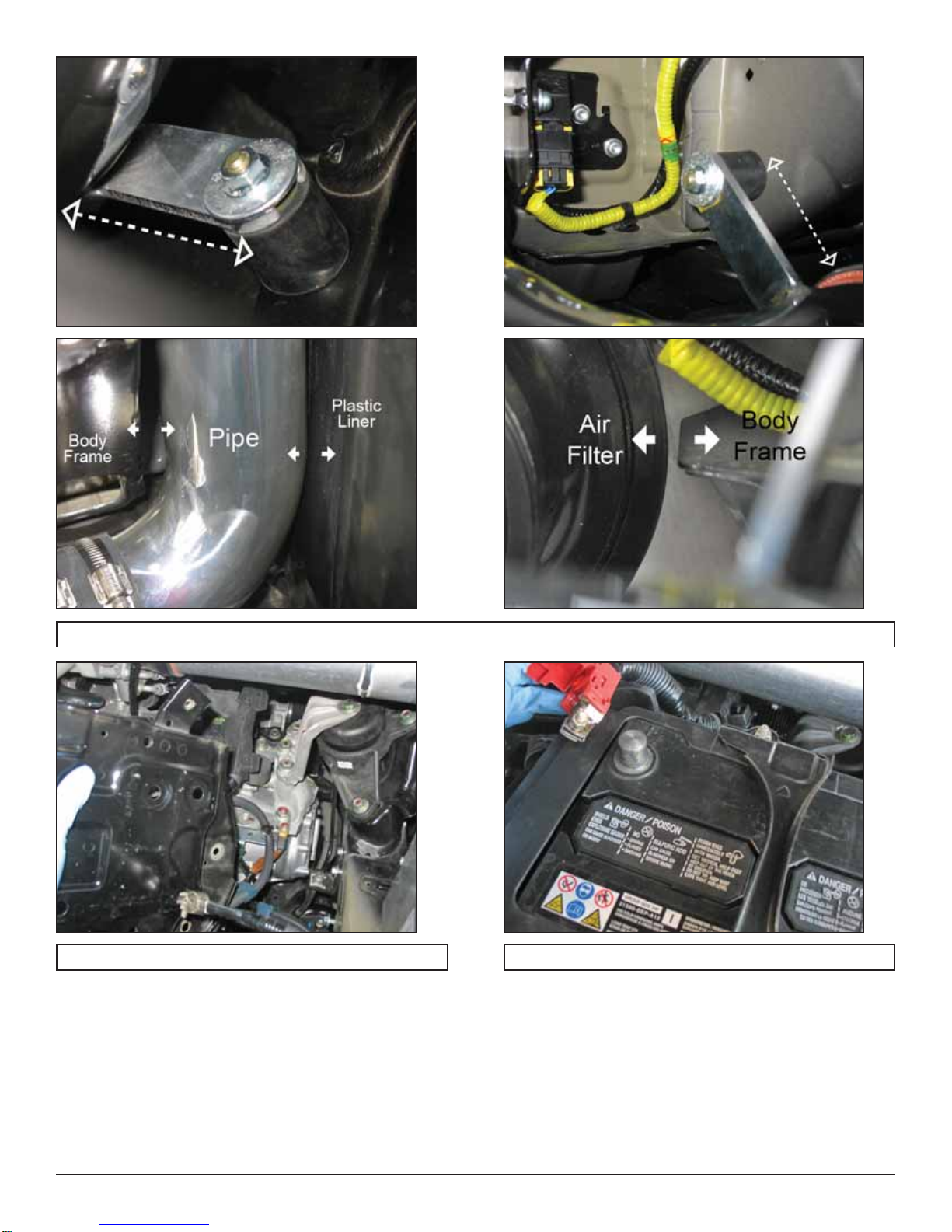
q. From previous steps 3i and 3p, adjust the brackets to allow clearance in the indicated areas shown in the photos.
r. Install the battery bracket. s. Install the battery and reconnect the positive lead.

12
t. Wheel well liner and bottom plastic tray: Install the
wheel well liner, bottom plastic tray and any hardware
that was removed during steps 2p-2q.
NOTE: Failure to install the fender liner will result
in diminished performance and increase the po-
tential for engine damage due to water ingestion in
rainy conditions.
u. Install the driver side wheel using the factory torque
specification (see owner’s manual).
Factory airbox system installed AEM®intake system installed
4. Reassemble Vehicle
a. Position the inlet pipes for the best fitment. Be sure that the pipes or any other components do not contact any part
of the vehicle. Tighten the rubber mount, all bolts, and hose clamps.
b. Check for proper hood clearance. Re-adjust pipes if necessary and re-tighten them.
c. Inspect the engine bay for any loose tools and check that all fasteners that were moved or removed are properly
tightened.
d. Reconnect negative battery terminals and start engine. Let the vehicle idle for 3 minutes. Perform a final inspection
before driving the vehicle.
5. CARB Sticker Placement
a. The C.A.R.B. exemption sticker, (attached), must be visible under the hood so that an emissions inspector can see
it when the vehicle is required to be tested for emissions. California requires testing every two years, other states
may vary.

13
AEM Air Intake System Warranty Policy
AEM®warrants that its intake systems will last for the life of your vehicle. AEM will not honor this warranty due to mechani-
cal damage (i.e. improper installation or fitment), damage from misuse, accidents or flying debris. AEM will not warrant
its powder coating if the finish has been cleaned with a hydrocarbon-based solvent. The powder coating should only be
cleaned with a mild soap and water solution. Proof of purchase of both the vehicle and AEM intake system is required for
redemption of a warranty claim.
This warranty is limited to the repair or replacement of the AEM part. In no event shall this warranty exceed the original
purchase price of the AEM part nor shall AEM be responsible for special, incidental or consequential damages or cost
incurred due to the failure of this product. Warranty claims to AEM must be transportation prepaid and accompanied with
dated proof of purchase. This warranty applies only to the original purchaser of product and is nontransferable. Improper
use or installation, use for racing, accident, abuse, unauthorized repairs or alterations voids this warranty. AEM disclaims
any liability for consequential damages due to breach of any written or implied warranty on all products manufactured by
AEM. Warranty returns will only be accepted by AEM when accompanied by a valid Return Merchandise Authorization
(RMA) number. Credit for defective products will be issued pending inspection. Product must be received by AEM within
30 days of the date RMA is issued.
6. Service and Maintenance
a. It is recommended that you service your AEM®Dryflow™ filter every 20,000 miles for optimum performance. Use
AEM Dryflow cleaning kit part # 21-110.
b. Use aluminum polish to clean your polished AEM®intake tube.
c. Use window cleaner to clean your powder coated AEM®intake tube. (NOTE: DO NOT USE aluminum polish on
powder coated AEM intake tubes).
AIR INTAKE CAR ACCESSORIES
Table of contents
Other AEM Automobile Part manuals


Popular Automobile Part manuals by other brands


 installation instructions")


Edelbrock
Edelbrock 68722 installation instructions

BBK
BBK 1763 installation instructions

Airaid
Airaid 300-165 installation instructions

Minebea
Minebea Rod End Bearing RBT Specification sheet

Edge Products
Edge Products GM Duramax 20200 installation instructions

Edelbrock
Edelbrock 2934 installation instructions