AEM 21-8223 Service manual

Equipped with AEM® Dryow™ Filter
No Oil Required!
INSTALLATION INSTRUCTIONS
PART NUMBER: 21-8223
AEM Induction Systems 1 (800) 992-3000 WWW: http://www.aemintakes.com
2011-2014 DODGE Challenger V8-5.7L
2011-2014 DODGE Charger V8-5.7L
2008-2010 DODGE Challenger V8-6.1L C.A.R.B. E.O. # D-670-6
2009-2010 DODGE Challenger V8-5.7L C.A.R.B. E.O. # D-670-6
2009-2010 DODGE Charger V8-6.1L C.A.R.B. E.O. # D-670-6
2009-2010 DODGE Charger V8-5.7L C.A.R.B. E.O. # D-670-6
SOME INTAKE SYSTEMS ARE NOT LEGAL FOR
SALE OR USE ON ANY POLLUTION CONTROLLED
MOTOR VEHICLE IN CALIFORNIA OR STATES
ADOPTING CALIFORNIA EMISSION PROCEDURES.
See aemintakes.com for CARB status on each part for a specific vehicle
2
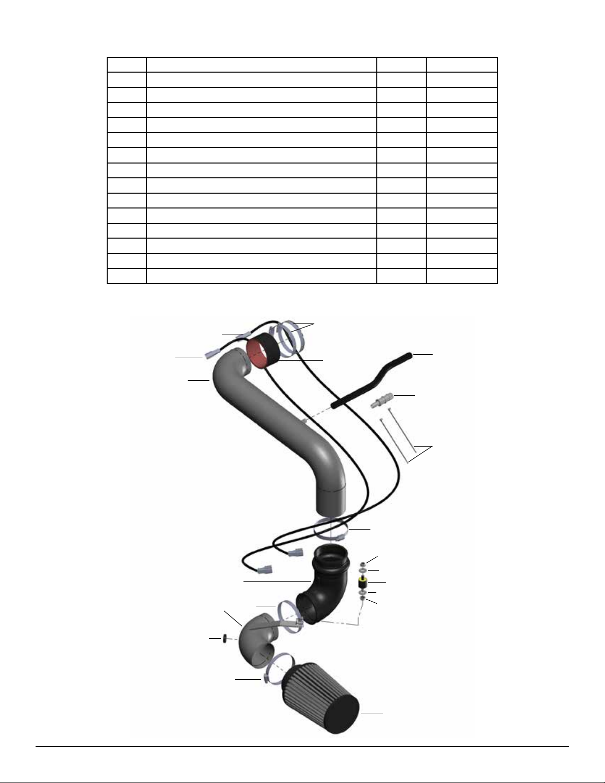
Description Qty. Part Number
PARTS LIST
A
B
C
D
E
E
F
F
G
H
I
J
J
J
J
K
L
M
N
O
A Upper Pipe, Intake 1 2-1406
B Lower Pipe, Intake 1 2-1407
C Hose, Hump 3.50/3.50x9.00” 90 Deg. 1 5-1037
D Mount, Rubber 1” X 8mm 1 1228560
E Washer, 8mm Soft Mount 2 559960
F Nut, M8 Hex Serrated 2 444.460.08
G Grommet; 1”OD,1/2”ID,1/2”Thk. 1 08064
HAir Filter Assy. 3.5” X 7” Dryow Element 1 21-2147DK
I Hose, Silicone 3.50”ID x2”L 1 5-351
J 1/2” Bnd. Hose Clamp, 3.15”-4.00” 5 9456
K Hose; 1/2”ID X 14”L 1 5-5014
*L Extension Harness; IAT 1 21698
MZip Tie,6” Long 2 1-113
N Hose Adapter, 3/4” X 1/2” 1 8-146
*O Extension Harness; IAT 1 21781
* Because the stock IAT connectors vary among Dodge vehicles of the same model year, your AEM®intake
system includes two IAT extension harness kits. You will only use 1 of the 2 extension harness kits provided.
Use the appropriate harness to t your vehicle’s IAT connector. (Item L or O.)
3
1. Preparing Vehicle
a. Make sure vehicle is parked on level surface.
b. Set parking brake.
c. If engine has run in the past two hours, let it cool down.
d. Disconnect the negative battery terminal.
e. Raise the front of the vehicle with a jack. Refer to your owner’s manual for proper jack and jack stand placement to
properly support vehicle. Support your vehicle using properly rated jack stands before wheel removal or while work
ing under the vehicle.
NEVER WORK UNDER A VEHICLE WITHOUT USING JACK STANDS.
f. Do not discard stock components after removal of the factory system.
Read and understand these instructions BEFORE attempting to install this product.
Failure to follow installation instructions and not using the provided hardware may
damage the intake tube, throttle body and engine.
The AEM® intake system is a performance product that can be used safely during mild weather
conditions. During harsh and inclement weather conditions, you must return your vehicle to
stock OEM air box and intake tract conguration. Failure to follow these instructions will void
your warranty.
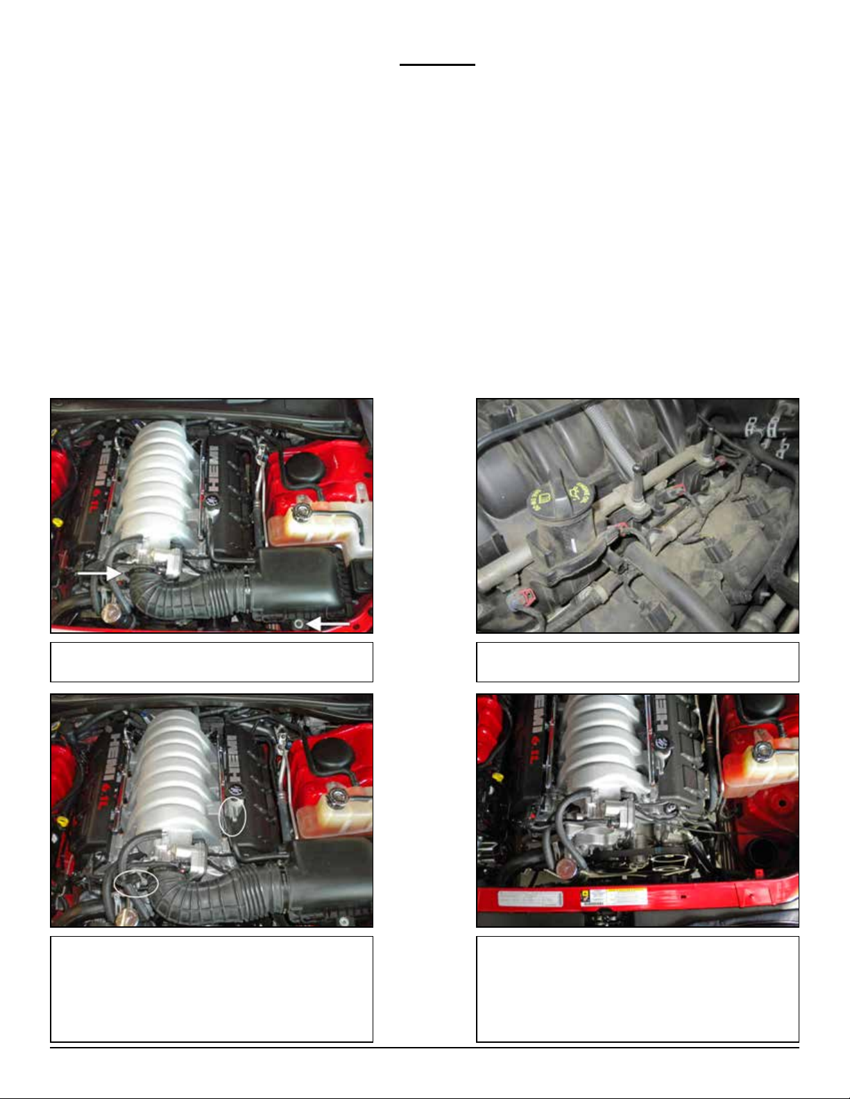
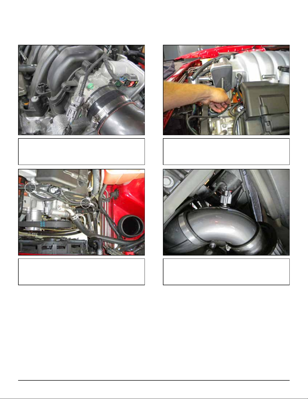
a. Remove the bolt securing the OEM air box and
loosen the hose clamp at the throttle body.
b. Pull to remove the crank case breather hose
from the nipple on the head cover.
c. Unplug the IAT sensor. To unplug the IAT sen-
sor, slide the red tab back to unlock the latch on
the plug, then press in on the latch and pull the
plug off of the sensor. For “grey” tabbed connec-
tors, push the top of the gray tab in and simply pull
the connector off.
d. Pull the rubber inlet hose off of the throttle body,
then lift and remove the OEM air box assembly.
2. Removal of stock intake system

4
e. Carefully remove the IAT sensor from the OEM
rubber inlet hose. Set the sensor aside for future
use.
f. In the wheel well area on each side, remove the
3 clips securing the belly pan.
g. From underneath the car, remove: 3 clips, 7
screws, and 2 bolts from the belly pan. (May vary
with each vehicle.)
h. Remove the belly pan.
i. For maximum performance from your intake sys-
tem, you may choose to remove the air deector.
If equipped, the air deector will be located behind
the lower grill on the driver side. Removing this
will provide additional cold air ow to the air lter.
j. To remove the air deector, remove the ve
plastic rivets securing it to the fascia. The rivets
can be removed by pulling the center pin out from
the back side of the rivet.
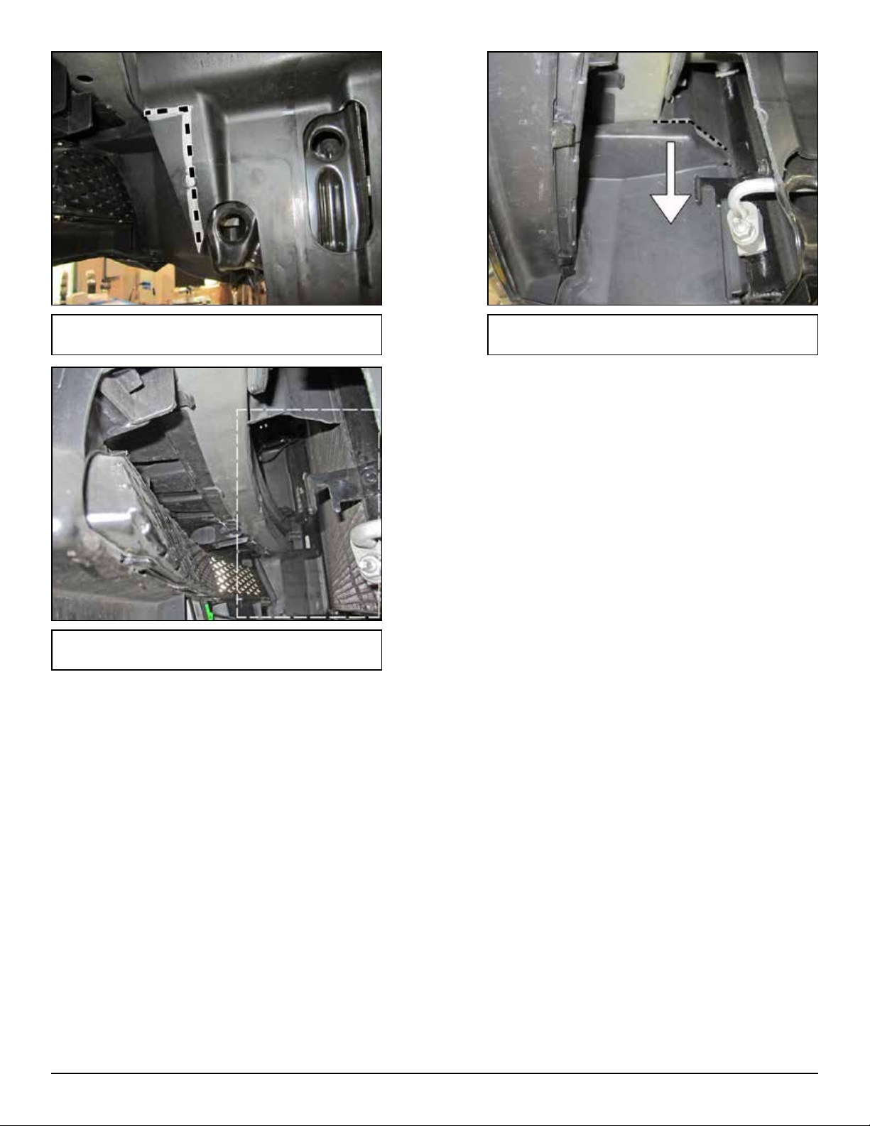
5
k. 2011-13 Dodge Charger Only: Locate the
deector and trim the specied area.
l. 2011-13 Dodge Charger Only: Locate the front
deector and trim the specied area.
m. 2011-13 Dodge Charger Only: Front deector
after specied area is trimmed.
6
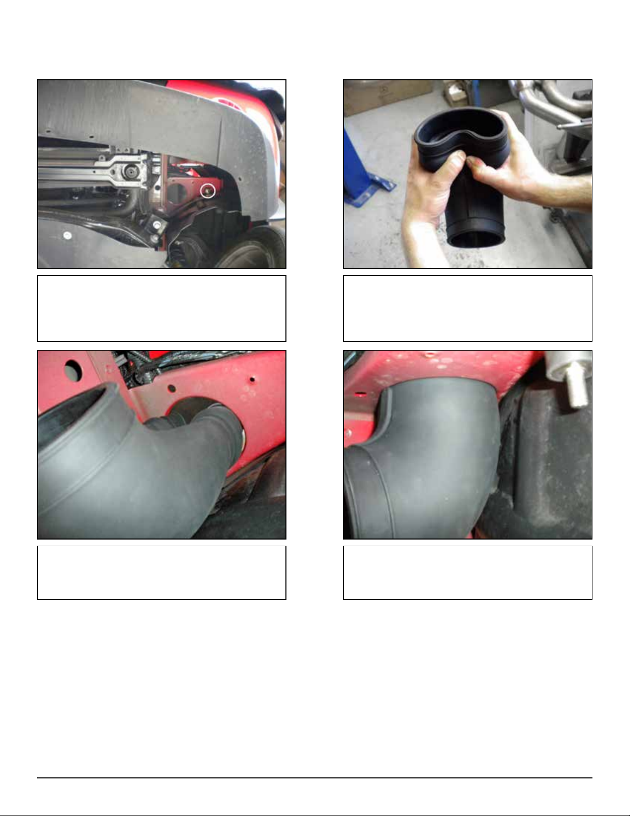
d. From underneath the vehicle, hold the collapsed
coupler rmly, then insert it into the large hole in the
sheet metal.
e. Make sure that the hump is all the way through
the hole, then release the coupler and manipulate
it until the sheet metal “snaps” into the grove in the
coupler.
3. Installation of Lower Intake System.
a. When installing the intake system, do not completely tighten the hose clamps or mounting hardware until instructed
to do so.
b. From underneath the car, install the M8 rubber
mount through the slotted hole in the sheet metal,
secure with 1 M8 washer and nut. Do not completely
tighten the M8 nut, this will allow room for adjust-
ment.
c. Hold the rubber coupler as shown, squeeze the
hump end of the coupler to collapse it into itself.
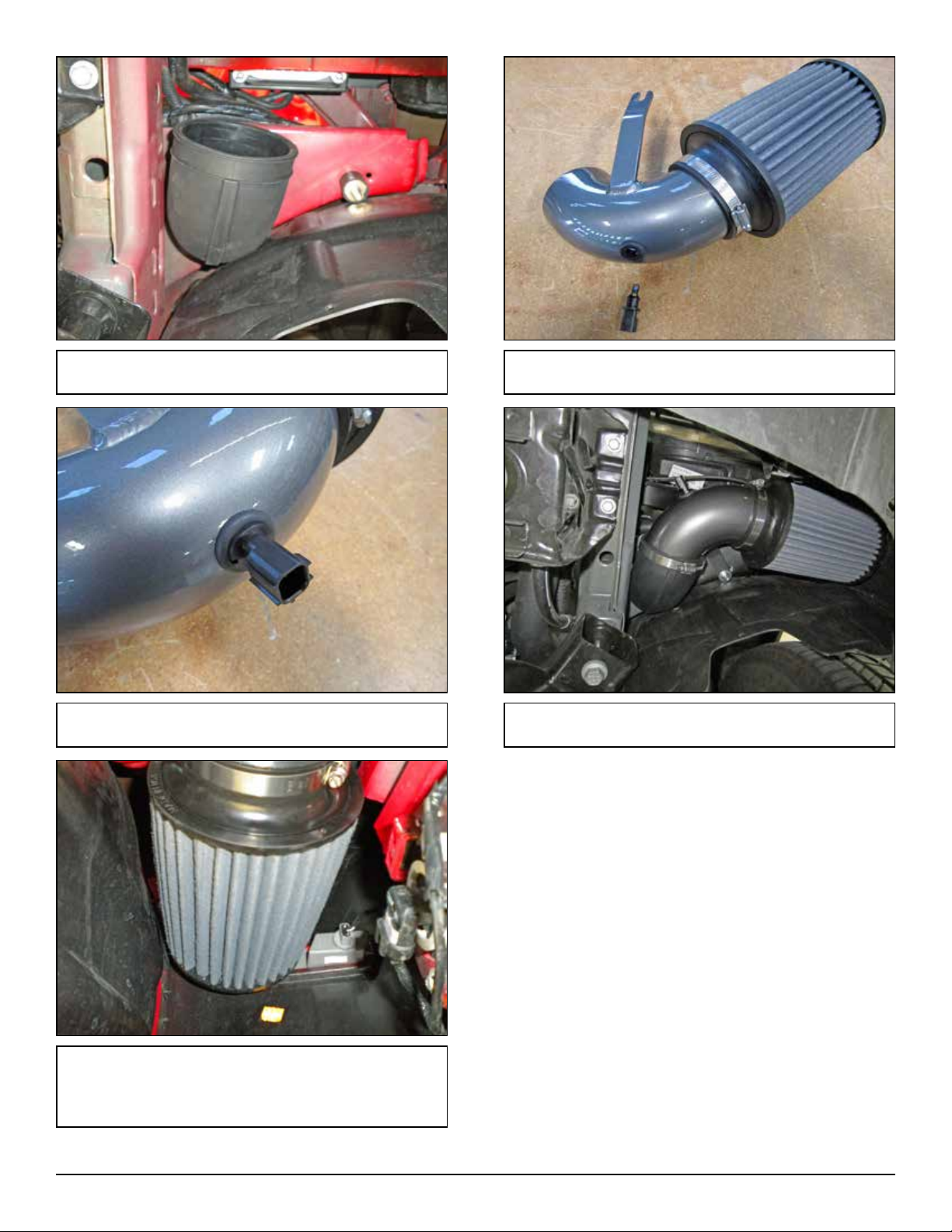
7
j. Adjust the lower pipe assembly so that there is equal
space between the lter, bumper support, fender liner,
and marker lamp. When a good t is achieved, tighten
both nuts on the rubber mount and the #56 clamp.
h. Carefully install the IAT sensor into the
grommet.
i. Install the lower pipe assembly as shown using one
M8 washer, one M8 nut, and one #56 clamp.
f. Orient the coupler as shown. g. Install the grommet into the lower pipe and
attach the lter with one #56 clamp as shown.
8
d. Route the IAT extension harness and secure it with
the two zip ties as shown. Position the female IAT
connector next to the lower intake tube.
e. From underneath the vehicle, plug the female IAT
connector into the IAT sensor in the lower intake tube.
Pull the red lock tab up to secure the connector.
4. AEM® IAT Extension Harness Kit Installation
a. Because the stock IAT connectors vary among Dodge vehicles of the same model year, your AEM®intake system
includes two IAT extension harness kits. You will only use 1 of the 2 extension harness kits. Use the
appropriate harness to t your vehicle’s IAT connector.
c. Route the IAT extension harness underneath the
throttle body and towards the driver side of the engine.
b. Select the appropriate IAT extension harness based
on your vehicle’s IAT connector. (Item L or O.)
Connect the male connector to the factory harness as
shown. Pull up on the red tab to lock it.

9
e. The lower end of the pipe should be inserted
into the rubber coupler to a depth of about ¾” to
1”. Slide the pipe all the way into the throttle body
coupler until it bottoms out. Once proper tment is
achieved, tighten the two remaining hose clamps.
d. Insert the lower end of the upper intake pipe
into the rubber coupler, and then carefully angle
the other end into the throttle body coupler. The
hose clamp on the rubber coupler may need to be
extra loose to achieve this.
5. Installation of Upper Intake System
a. When installing the intake system, do not completely tighten the hose clamps or mounting hardware until instructed
to do so.
b. Loosely install a #56 hose clamp over the upper
opening of the elbow hump hose.
c. Install the silicone coupler and two #56 clamps
onto the throttle body. Slide the coupler all the way
onto the throttle body and secure it by tightening
one of the #56 clamps.

10
6. Reassemble Vehicle
a. Position the inlet pipes for the best tment. Be sure that the pipes or any other components do not contact any part
of the vehicle. Tighten the rubber mount, all bolts, and hose clamps.
b. Check for proper hood clearance. Re-adjust pipes if necessary and re-tighten them.
c. Inspect the engine bay for any loose tools and check that all fasteners that were moved or removed are properly
tightened.
d. Reconnect the negative battery terminal and start engine. Let the vehicle idle for 3 minutes. Perform a nal
inspection before driving the vehicle.
7. CARB Sticker Placement
a. The C.A.R.B. exemption sticker, (included), must be visible under the hood so that an emissions inspector can see
it when the vehicle is required to be tested for emissions. California requires testing every two years, other states
may vary.
h. Install the belly pan with the 9 clips, 7 screws,
and 2 bolts removed in steps 2f and 2g.
AEM®intake system installed
f. For Most Applications: Install the supplied ½”
ID hose between the crank case vent on the head
cover and the nipple on the upper intake pipe.
Secure the ½” hose with two small hose clamps.
g. On some 5.7L engines: Connect the stock
crank case vent hose to the supplied plastic adap-
tor nipple. Connect a 4” section of the ½” ID hose
onto the other end of plastic adaptor nipple. Con-
nect the hose to the intake pipe and secure with
the small hose clamps as shown.

11 10-331K
03/18/14
AEM Air Intake System Warranty Policy
AEM®warrants that its intake systems will last for the life of your vehicle. AEM will not honor this warranty due to mechani-
cal damage (i.e. improper installation or tment), damage from misuse, accidents or ying debris. AEM will not warrant
its powder coating if the nish has been cleaned with a hydrocarbon-based solvent. The powder coating should only be
cleaned with a mild soap and water solution. Proof of purchase of both the vehicle and AEM intake system is required for
redemption of a warranty claim.
This warranty is limited to the repair or replacement of the AEM part. In no event shall this warranty exceed the original
purchase price of the AEM part nor shall AEM be responsible for special, incidental or consequential damages or cost
incurred due to the failure of this product. Warranty claims to AEM must be transportation prepaid and accompanied with
dated proof of purchase. This warranty applies only to the original purchaser of product and is nontransferable. Improper
use or installation, use for racing, accident, abuse, unauthorized repairs or alterations voids this warranty. AEM disclaims
any liability for consequential damages due to breach of any written or implied warranty on all products manufactured by
AEM. Warranty returns will only be accepted by AEM when accompanied by a valid Return Merchandise Authorization
(RMA) number. Credit for defective products will be issued pending inspection. Product must be received by AEM within
30 days of the date RMA is issued.
If you have a warranty issue, please call (800) 992-3000 and our customer service department will assist you. A proof of
purchase is required for all AEM warranty claims.
For technical inquiries
e-mail us at
or
call us at
800.992.3000
8. Service and Maintenance
a. AEM Induction Systems requires cleaning the intake system’s air lter element every 100,000 miles. When used in
dusty or off-road environments, our lters will require cleaning more often. We recommend that you visually inspect
your lter once every 25,000 miles to determine if the screen is still visible. When the screen is no longer visible
some place on the lter element, it is time to clean it. To clean, purchase our Synthetic air lter cleaner, part number
1-1000 and follow the easy instructions.
b. Use window cleaner or a mild soap and water solution to clean your powder coated AEM®intake tube.
NOTE: DO NOT USE aluminum polish on powder coated AEM® intake tubes.
SOME INTAKE SYSTEMS ARE NOT LEGAL FOR
SALE OR USE ON ANY POLLUTION CONTROLLED
MOTOR VEHICLE IN CALIFORNIA OR STATES
ADOPTING CALIFORNIA EMISSION PROCEDURES.
See aemintakes.com for CARB status on each part for a specific vehicle
Table of contents
Other AEM Automobile Part manuals


Popular Automobile Part manuals by other brands

Edelbrock
Edelbrock 2860 installation instructions

Dakota Digital
Dakota Digital MCL-2002 manual

Moss
Moss Automobile Parts user manual

Ironclad
Ironclad Automobile Parts Instructions for installation

K&N Engineering
K&N Engineering Typhoon 69-2520 installation instructions

Air Lift
Air Lift LoadLifter 5000 Series installation guide


