AEM SM60 N300-001 User manual

SPECIAL NOTICE
This product is now licensed to Anodyne Electronics Manufacturing (AEM) from Northern
Airborne Technology (NAT). AEM is responsible for all matters related to this product, including
sales, support and repair services.
Please note the transition to convert product manuals and supporting documentation is an
ongoing process and is being addressed on an ‘as needed’ basis.
All references to NAT product part numbers (and associated images) are equivalent to AEM
product part numbers.
Contact info:
Anodyne Electronics Manufacturing Corp.
#15-1925 Kirschner Road
Kelowna B.C. Canada
V1Y 4N7
Email: support@aem-corp.com
Toll Free: 1-888-763-1088
Phone: 1-250-763-1088
Fax: 1-250-763-1089
www.aem-corp.com
CONFIDENTIAL AND PROPRIETARY TO ANODYNE ELECTRONICS MANUFACTURING CORP.
INSTALLATION AND OPERATION MANUAL
Rev: 2.00 May 26, 2012
Anodyne Electronics Manufacturing Corp.
15-1925 Kirschner Road
Kelowna, BC, Canada.
V1Y 4N7
Telephone (250) 763-1088
Facsimile (250) 763-1089
Website: www.aem-corp.com
© 2012 Anodyne Electronics Manufacturing Corp. (AEM),
All Rights Reserved
SM60
N300
-001 and N300-002
Audio Controller

N300-001 and N300-002 Audio Controller
SM60 Installation and Operation Manual
Installation and Operation Manual Page ii
ENG-FORM: 820-0100.DOTX
CONFIDENTIAL AND PROPRIETARY TO ANODYNE ELECTRONICS MANUFACTURING CORP.
COPYRIGHT STATEMENT
© 2012 Anodyne Electronics Manufacturing Corp. (AEM), All Rights Reserved
This publication is the property of AEM and is protected by Canadian copyright laws.
No part of this document may be reproduced or transmitted in any form or by any
means including electronic, mechanical, photocopying, recording, or otherwise, without
the prior written permission of AEM.

N300-001 and N300-002 Audio Controller
SM60 Installation and Operation Manual
Installation and Operation Manual Page iii
ENG-FORM: 820-0100.DOTX
CONFIDENTIAL AND PROPRIETARY TO ANODYNE ELECTRONICS MANUFACTURING CORP.
Prepared By:
Checked By:
Approved By:
The status of this installation and operation manual is controlled by the revision shown on the title page.
The status of each section is controlled by revision shown in the footer of each page. All revisions
affecting sections of this manual have been incorporated.
ISSUE/REVISION RECORD
Manual Issue
Number
Section
Revision Number
Revision Description
Issue Date
4.01
Section 1 Rev: 1.00
Section 2 Rev: 1.00
Section 3 Rev: 1.00
Update to current templates. Sep 26
, 2008
AEM MANUAL REVISIONS
Section
Revision Number
Revision Description
Date
All
Rev 2.00
Updated template
May 26, 2012
Tony Pearson
Designer
May 26, 2012
Loen Clement
Designer
Jun 26/12
Tom Betzelt
Product Support
Manager
June 26, 2012

N300-001 and N300-002 Audio Controller
SM60 Installation and Operation Manual
Installation and Operation Manual Page iv
ENG-FORM: 820-0100.DOTX
CONFIDENTIAL AND PROPRIETARY TO ANODYNE ELECTRONICS MANUFACTURING CORP.
Table of Contents
Section Title Page
1.0 Description
1.1 Introduction 1-1
1.2 Product Description 1-1
1.3 Design Features 1-1
1.3.1 N300-001 1-1
1.3.2 N300-002 1-1
1.3.3 Performance/Function (N300-001 and N300-002) 1-1
1.3.4 Performance/Function (N300-001 only) 1-2
1.4 Specifications 1-2
1.4.1 Electrical Specifications 1-2
1.4.2 Physical Specifications 1-5
1.4.3 Environmental Specifications 1-6
1.4.4 Product Approval 1-6
2.0 Installation
2.1 Introduction 2-1
2.2 Unpacking and Inspection 2-1
2.2.1 Warranty 2-1
2.3 Continued Airworthiness 2-1
2.4 Installation Procedures 2-2
2.4.1 Cautions 2-2
2.4.2 Cabling and Wiring 2-2
2.4.3 Mechanical Mounting 2-3
2.4.4 Post-Installation Checks 2-3
2.5 Adjustments and Connections 2-4
2.5.1 Internal Adjustments and Selections 2-4
2.6 Accessories Required But Not Supplied 2-5
2.6.1 N300-001 Installation Kits 2-5
2.6.2 N300-002 Installation Kits 2-5
2.6.3 Installation Kits 2-5
2.7 Installation Drawings 2-6
3.0 Operation
3.1 Introduction 3-1
3.2 General Information 3-1
3.2.1 N300-001 3-1
3.2.2 N300-002 3-1
3.3 Controls and Indicators 3-2
3.3.1 Receiver Controls (RX SEL) 3-2
3.3.2 Mute Volume (MVOL) - N300-001 only 3-3
3.3.3 Transceiver Controls 3-3
3.3.4 Transceiver Volume Controls 3-3
3.3.5 CALL Pushbutton 3-3
3.3.6 Emergency EMER/NORM Switch 3-4
3.3.7 VOX Control 3-4
3.3.8 External Controls 3-4

N300-001 and N300-002 Audio Controller
SM60 Installation and Operation Manual
May 26, 2012 Rev: 2.00 Page 1-1
ENG-FORM: 800-0100.DOTX
CONFIDENTIAL AND PROPRIETARY TO ANODYNE ELECTRONICS MANUFACTURING CORP.
Section 1.0 Description
1.1 Introduction
Information in this section consists of product description, design features and specifications for the
N300-001 and N300-002 Audio Controller. All derivative product information shall be contained in the
applicable manual supplement, which may be obtained from AEM as required. Review all notes, warning
and cautions.
1.2 Purpose of Equipment
The N300 Audio Controller is compatible with low impedance military headsets. The N300 controls the audio
from multiple receivers, and allows transmission of mic audio to a selected transmitter. VOX Intercom
operation is also provided on a proprietary tie line to multiple units. A redundant backup system is selectable
from the front panel.
1.3 Design Features
The N300 Audio Controllers are Dzus rail mounted boxes with NVIS Green “B” compliant lighted
faceplates. All knobs are gray with illuminated ‘lubber’ lines for high contrast and visibility in day and
night conditions.
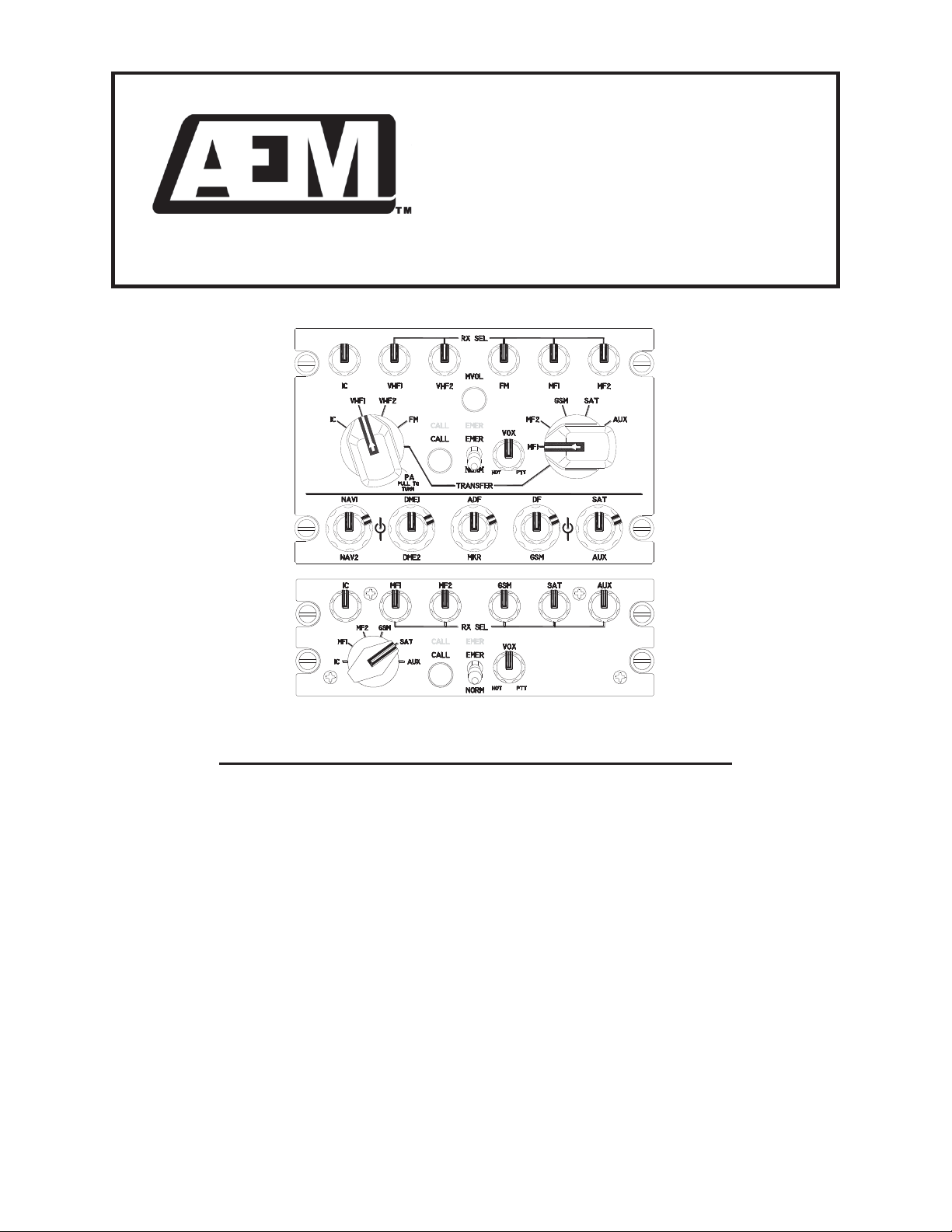
1.3.1 N300-001
The N300-001 supports nine transceivers (including PA) and seven additional receivers. It features two
rotary transmit select switches, individual RX volume controls for each radio input, a front panel VOX
squelch control, EMER/NORM operation select switch, CALL pushbutton switch, and intercom volume
control. There are also two unswitched, direct audio inputs for alert/warning signal inputs.
1.3.2 N300-002
The N300-002 supports five transceivers. It features a single rotary transmit select switch, individual RX
volume controls for each radio input, a front panel VOX squelch control, EMEER/NORM operation select
switch, CALL pushbutton switch, and intercom volume control.
1.3.3 Performance/Function (N300-001 and N300-002)
The emergency switch will transfer the microphones and headphones over to a second internal system.
A green annunciator will illuminate when the emergency position is selected.
The CALL push button will key both microphones for intercom operation while outputting a ground signal
and illuminating a green annunciator on the front panel.
When the transmit selector is in the IC position, the ICS mode will operate PTT only from either TX or IC
PTT key.

N300-001 and N300-002 Audio Controller
SM60 Installation and Operation Manual
May 26, 2012 Rev: 2.00 Page 1-2
ENG-FORM: 800-0100.DOTX
CONFIDENTIAL AND PROPRIETARY TO ANODYNE ELECTRONICS MANUFACTURING CORP.
The intercom audio will be live (Hot Mic) when the VOX potentiometer is set fully ccw (but not in the
detent position). In the fully cw position, the intercom will operate in PTT mode. In the detent position,
the VOX circuit will operate at a predetermined factory setting.
The sidetone from the selected transmitter is attenuated to be below the RX audio level and will follow the
front panel setting. This option is internally activated/deactivated via an internal switch.
The microphone input utilizes an automatic level control amplifier for maximum intelligibility without
distortion.
1.3.4 Performance/Function (N300-003 only)
The radio inputs are designed to provide a minimum output even when the respective volume control is
set to minimum. If the control is set fully counter-clockwise into the ‘detent’ position, the input is turned
off. The transceiver audio inputs are also controlled by the Auto RX circuit. This ensures the radio
selected at the left or right rotary switch will be audible regardless of the position of the associated receive
volume control. If the volume setting for the radio selected on the transmit selector switch is set higher
than the Auto RX level, the panel volume potentiometer setting will take precedence.
Selection of a transceiver for transmit microphone operation is achieved by rotating the respective rotary
switch to the appropriate position. The left switch selects the respective transceiver directly, while the
right switch becomes active only when the left switch is selected to the TRANSFER position. The left
switch is also protected from inadvertently being selected to the PA position by a mechanical stop. The
knob must be lifted and turned to select/deselect PA.
The MVOL momentary push button switch will mute all audio except the auto receive audio and direct
audio. It can also be activated from an external source (switch).
The SWAP key input is routed to one of four SWAP key outputs when one of the two rotary selector
switches is in either the VHF1, VHF2, FM2 or FM3 positions. These lines are fully floating so the SWAP
key signal can be defined by the customer. When the rotary selector switches are not in any of these four
positions, all SWAP key outputs are open circuit.
1.4 Specifications
1.4.1 Electrical Specifications
Power Supply Multiple switchers and linear regulators with
reverse and over voltage protection
Input Voltage 30.3 Vdc Maximum
(normal operating) 27.5 Vdc (nominal)
24.8Vdc(minimum)
18.0 Vdc (emergency)
12.0 Vdc (starting, degraded performance)
(abnormal operation) 32.2 Vdc (maximum)
27.5Vdc(nominal)
16.0 Vdc (minimum)

N300-001 and N300-002 Audio Controller
SM60 Installation and Operation Manual
May 26, 2012 Rev: 2.00 Page 1-3
ENG-FORM: 800-0100.DOTX
CONFIDENTIAL AND PROPRIETARY TO ANODYNE ELECTRONICS MANUFACTURING CORP.
Input current: 0.5 Amps max. @ 27.5 Vdc (total)
Lighting:
N300-001 300 mA max. @ 27.5 Vdc
N300-002 200 mA max. @ 27.5 Vdc
Input Signals
Quantity:
N300-001 16 receive channels including PA sidetone
2 direct channels
2micchannels
1 ICS tie channel
2transmitPTTkeyinputs
2ICSPTTkeyinputs
1TXswapkeyinput
1MVOLkeyinput
N300-002 5 receive channels
2micchannels
1 ICS tie channel
2transmitPTTkeyinputs
2ICSPTTkeyinputs
Rated Level: N300-001 1 –10 Vrms for receive and direct inputs
(internally selectable in 1 V increments)
N300-002 1 –10 Vrms for receive and direct inputs
(internally selectable in 1 V increments)
N300-001 only TX swap command <100 mA input current
Impedance: N300-001 5 kΩ± 10% for receive and direct inputs
N300-002 5 kΩ±10% for receive input
N300-001/-002 5 ±2 Ωfor dynamic 5 Ωmic input
2kΩ±10% for SuperNAT ICS tie input
Circuitry Type: All audio inputs are balanced accept for the
SuperNATICSTieinput.
Coupling: < -60 dB input-to-input crosstalk
Output Signals
Quantity: N300-001 2 headphone outputs
9 transmitter mic outputs
9 transmitter keyline outputs
1 CVR output
1 composite receive audio output
1 ICS tie channel
4 TX swap outputs

N300-001 and N300-002 Audio Controller
SM60 Installation and Operation Manual
May 26, 2012 Rev: 2.00 Page 1-4
ENG-FORM: 800-0100.DOTX
CONFIDENTIAL AND PROPRIETARY TO ANODYNE ELECTRONICS MANUFACTURING CORP.
N300-002 2 headphone outputs
5 transmitter mic outputs
5 transmitter keyline outputs
1 CVR output
1 composite receive audio output
1 ICS tie channel
Rated level:
Headphone outputs: 400 mW (1.8 Vrms) minimum into 8 Ωat fully cw
position (see Note 1)
Sidetone: 6 r1 dB below selected receive output
TX mic output: 250 mVrms nominal into 100 Ω
Transmitter keyline output: 1A max.
CVR output: 450 r50 mVrms into 5 kΩ
Composite receive output: > 2.5 Vrms to 600 Ω
SuperNAT ICS output: 1.2 Vrms + /-100 mV into 2 kΩ(see Note 2)
Circuitry Type: Headphones, CVR, and mic outputs are balanced,
floating transformer outputs.
Headphone Outputs Frequency Response
Receive inputs < 3 dB from 350 Hz to 6000 Hz
Direct inputs (N300-001) < 3 dB from 350 Hz to 6000 Hz
Intercom < 3 dB from 350 Hz to 3000 Hz
TX mic Output: < 3 dB from 350 Hz to 6000 Hz
CVR Output : < 3 dB from 375 Hz to 5000 Hz
Composite RX Output: < 3 dB from 350 Hz to 6000 Hz
Distortion: < 10% THD @ rated power output
Audio Noise Level Without Signal:
N300-001 > 60 dB down from rated output
CVR !50 dB down from rated output
N300-002 > 40 dB down from rated output
CVR !50 dB down from rated output
Coupling: < -55 dB input-to-output crosstalk
Output Regulation: < 10% distortion / '7 dB max. of rated output power
at 400% and 75% of rated load
Bi-directional 1 ICS call input/output
ICS call <10 mA input current, active low (3 Vdc max.)
CALL and EMER Annunciators Illuminate green when activated

N300-001 and N300-002 Audio Controller
SM60 Installation and Operation Manual
May 26, 2012 Rev: 2.00 Page 1-5
ENG-FORM: 800-0100.DOTX
CONFIDENTIAL AND PROPRIETARY TO ANODYNE ELECTRONICS MANUFACTURING CORP.
Notes: 1) The headphone output level specified is as measured with the rated input. Cable lengths must
be considered for the input and output connections as they will affect the measurements.
Rated output can be achieved with a maximum of 1.5 Ohms of resistance introduced by the
headphone output cables.
2) The SuperNAT Tie Line is not compatible with existing NAT tie lines.
1.4.2 Physical Specifications
1.4.2.1 N300-001
Height 3.75” (95.3 mm) max
Depth 6.21” (157.6 mm) max, behind panel, excluding connector
Width 4.96” (126.0 mm) max, behind panel
Weight 3.8 lbs (1.7 kg) max
Mounting Dzus rail (four fasteners), 2.625” vertical spacing
Faceplate Laser engraved acrylic edge lit NVIS green “B” compliant
Material/Finish Chassis & cover are 5052-H32 brushed aluminum with
conversion coating finish
Connectors Two male 50-pin & one male 15-pin D-sub filtered connectors
with jack posts
1.4.2.2 N300-002
Height 1.88” (47.6 mm) max
Depth 6.30” (160.0 mm) max, behind panel, excluding connector
Width 4.96” (126.0 mm) max, behind panel
Weight 2.7 lbs (1.2 kg) max
Mounting Dzus rail (four fasteners), 0.75” vertical spacing
Faceplate Laser engraved acrylic edge lit NVIS green “B” compliant
Material/Finish Chassis & cover are 5052-H32 brushed aluminum with
Conversion coating finish
Connectors One male 50-pin & one male 15-pin D-sub filtered connectors
with jack posts

N300-001 and N300-002 Audio Controller
SM60 Installation and Operation Manual
May 26, 2012 Rev: 2.00 Page 1-6
ENG-FORM: 800-0100.DOTX
CONFIDENTIAL AND PROPRIETARY TO ANODYNE ELECTRONICS MANUFACTURING CORP.
1.4.3 Environmental Specifications
Temperature -40qC. to +70qC (operating)
-55qC. to +85qC(survival)
Vibration/Shock Conforms to DO-160C Cat. N
Humidity 95% non-condensing
Altitude 25,000 feet max
Qualification of the N300-001 and N300-002 Audio Controller was completed in accordance with
DO-160C Env. Cat. B4-BANXXXXXXABABUAXXX.
1.4.4 Product Approval
No TSO approval required.
End of Section 1.0

N300-001 and N300-002 Audio Controller
SM60 Installation and Operation Manual
May 26, 2012 Rev: 2.00 Page 2-1
ENG-FORM: 805-0100.DOTX
CONFIDENTIAL AND PROPRIETARY TO ANODYNE ELECTRONICS MANUFACTURING CORP.
Section 2.0 Installation
2.1 Introduction
Information in this section consists of unpacking and inspection procedures, installation procedures, post-
installation checks and installation drawings for the N300-001 and N300-002 Audio Controller.
Review all notes, warnings and cautions.
2.2 Unpacking and Inspection
Unpack the equipment carefully. Inspect the unit visually for damage due to shipping and report all such
claims immediately to the carrier involved. Note that each unit should have the following:
- N300-001 or N300-002 Audio Controller
- Product Information Card
- Certificate of Conformity or Release certification
Verify that all items are present before proceeding and report any shortage immediately to your supplier.
2.2.1 Warranty
All Anodyne Electronics Manufacturing Corp. (AEM) products are warranted for 2 years. See the website
www.aem-corp.com/warranty for complete details.
2.3 Continued Airworthiness
Maintenance of the N300-001 and N300-002 Audio Controller is ‘on condition’ only. Periodic maintenance
of this product is not required.

N300-001 and N300-002 Audio Controller
SM60 Installation and Operation Manual
May 26, 2012 Rev: 2.00 Page 2-2
ENG-FORM: 805-0100.DOTX
CONFIDENTIAL AND PROPRIETARY TO ANODYNE ELECTRONICS MANUFACTURING CORP.
2.4 Installation Procedures
2.4.1 Cautions
CAUTION:
In all installations that use the Dynamic microphone capability of the N300,
extreme care must be taken with the shielding and routing of the microphone
wiring. This is especially true of the 5 ohm Dynamic mic input, where typical
signals are in the range of 100 –
250 μVrms. Special wire with Mumetal
shielding should be considered if there are any concerns about installation
related noise. Do not bundle the microphone wiring with high-
level lines
(headphone, radio audio, coaxial cables, etc.).
Headset and/or helmet wiring may also need to be reviewed if using Dynamic
microphones. Many of the headsets and helmets on the market have minimal
shielding for the wiring associated with the mic and phone circuits. Those with
shielded wiring often use the Phone Lo co
nnection for the shield ground. In
the N300, the Phone Lo connection is not ground referenced, so the shielding
has no effect. This will result in substantial coupling of the Phone signal onto
the Microphone wires, leading to high levels of crosstalk in th
e intercom
system. These shielding considerations also apply to in
-
line PTT cordsets. If a
review of the headset wiring indicates there will be a problem with the shield
terminat
ion, it is acceptable to ground the Phone Lo connection to a local
ground at the headset jack/connector.
2.4.2 Cabling and Wiring
All wire shall be selected in accordance with the original aircraft manufacturer's Maintenance Instructions
or AC43.13-1B Change 1, Paragraphs 11-76 through 11-78. Unshielded wire types shall qualify to
MIL-W-22759 as specified in AC43.13-1B Change 1, Paragraphs 11-85, 11-86, and listed in Table 11-11.
For shielded wire applications, use Tefzel MIL-C-27500 shielded wire with solder sleeves (for shield
terminations) to make the most compact and easily terminated interconnect. Follow the connector map in
Section 2.7 as required.
Allow 3" from the end of the shielded wiring to the shield termination to allow the connector hood to be
easily installed. Reference the interconnect drawing in Section 2.7 for shield termination details. Note that
the hood is a "clamshell" hood, and is installed after the wiring is complete. Aircraft harnessing shall
permit the unit to be removed from the panel for easy access to all side adjustments. Do NOT mount the
unit until all adjustments have been performed.
Maintain wire segregation and route wiring in accordance with the original aircraft manufacturers
Maintenance Instructions.
Unless otherwise noted, all wiring shall be a minimum of 22 AWG, except power and ground lines, which
shall be a minimum of 20 AWG. Reference the Interconnect drawing for additional specifications. Check
that the ground connection is clean and well secured, and that it shares no path with any electrically noisy
aircraft accessories such as blowers, turn and bank instruments or similar loads. Power to this unit must
be supplied from a separate circuit breaker or fuse (fast blow), and not attached to any other circuit
breaker without additional protection. Verify that the selected circuit breaker size and wire gauge are
adequate for the installation using the techniques specified in AC43.13-1B Change 1, Paragraphs 11-47
through 11-51 and 11-66 through 11-69.

N300-001 and N300-002 Audio Controller
SM60 Installation and Operation Manual
May 26, 2012 Rev: 2.00 Page 2-3
ENG-FORM: 805-0100.DOTX
CONFIDENTIAL AND PROPRIETARY TO ANODYNE ELECTRONICS MANUFACTURING CORP.
2.4.3 Mechanical Mounting
Before the unit is mounted, make all functional tests, and trimpot adjustments. Be sure the harness has
enough clearance to permit the unit to be pulled out for re-adjustment, if needed later. Check that the unit
is securely fastened to the Dzus rail, and that the connector locks are tightened before any flight is
attempted.
2.4.4 Post-Installation Checks
2.4.4.1 Voltage/Resistance Checks
Do not attach the N300-001 until the following conditions are met.
Check the following:
a) Check P101, pins <2>, <4>, <19> and <21> for continuity to ground when the relevant
transmit key is activated.
b) Check P101, pins <36> and <38> for continuity to ground (less than 0.5:).
c) Check P102, pins <3>, <9>, <10> and <11> for continuity to ground (less than 0.5:).
d) Check P102, pins <1>, <2> and <8> for +28 Vdc relative to ground.
e) Check P103, pins <17> and <34> for continuity to ground when the relevant switch is closed.
Do not attach the N300-002 until the following conditions are met.
Check the following:
a) Check P101, pins <2>, <4>, <19> and <21> for continuity to ground when the relevant
transmit key is activated.
b) Check P101, pins <36> and <38> for continuity to ground (less than 0.5:).
c) Check P102, pins <3>, <9>, <10> and <11> for continuity to ground (less than 0.5:).
d) Check P102, pins <1>, <2> and <8> for +28 Vdc relative to ground.
2.4.4.2 Power On Checks
Power up the aircraft’s systems and confirm normal operation of all functions of the N300-001 or
N300-002. Refer to Section 3 (Operation) for specific operational details.
a) Check for correct radio audio and adjust for acceptable level.
b) Check all installed functions, and check the ICS and TX functions for all users.
Note: Significantly different headsets may have different microphone characteristics.
c) Check preset adjustments are completed before aircraft departure.
d) Check that the unit and its mating connector are secured before departure.
Note: The unit is shipped from the factory with all internal adjustments set to the normal test levels.
Once installed in the aircraft, it may be desirable to change some of these settings to best suit the
local operating environment.

N300-001 and N300-002 Audio Controller
SM60 Installation and Operation Manual
May 26, 2012 Rev: 2.00 Page 2-4
ENG-FORM: 805-0100.DOTX
CONFIDENTIAL AND PROPRIETARY TO ANODYNE ELECTRONICS MANUFACTURING CORP.
Upon satisfactory completion of all performance checks, make all required log book entries, electrical
load, weight and balance amendments and other documentation as required by your local regulatory
agency before releasing the aircraft for service.
2.5 Adjustments and Connections
The unit is shipped from the factory with all internal adjustments set to the normal test levels. Once
installed in the aircraft, it may be desirable to change some of these settings to best suit the local
operating environment. The internal adjustments are located along the sides and top of the unit.
Refer to Options drawings N300\001\404-0, N300\001\404-1, N300\001\404-2, N300\002\404-0 and
N300\002\404-1.
2.5.1 Internal Adjustments and Selections
2.5.1.1 ICS Tie
ICS Tie selects the gain of intercom channel to match number of units on the tie line.
2.5.1.2 RX Input Level
RX Input Level selects the input level for each RX input to match radio output.
2.5.1.3 Sidetone Enable
Sidetone Enable enables and disables the –6dB attenuation circuit for radio sidetone.
2.5.1.4 TX Mic Output
TX Mic Output provides for adjustment of each TX mic output to match the radio mic input requirements.
2.5.1.5 CVR
CVR provides for adjustment of the NORM/EMER CVR audio output.
2.5.1.6 VOX Delay
VOX Delay provides for adjustment of the VOX delay associated with the #1 and #2 NORM and EMER
microphone circuits.
2.5.1.7 VOX Preset
VOX Preset provides for adjustment of VOX Preset level (50 r10 uVrms).

N300-001 and N300-002 Audio Controller
SM60 Installation and Operation Manual
May 26, 2012 Rev: 2.00 Page 2-5
ENG-FORM: 805-0100.DOTX
CONFIDENTIAL AND PROPRIETARY TO ANODYNE ELECTRONICS MANUFACTURING CORP.
2.5.1.8 DIR and PA Volume Adjust (N300-001 only)
DIR and PA Volume Adjust provides for adjustment of the input level of audio signals connected to these
inputs.
2.6 Accessories Required But Not Supplied
2.6.1 N300-001 Installation Kits
Installation kit p/n N300-001-IKC (crimp) is required to complete the installation. The kit consists of two 50
Pin D-min Female Crimp Kits D50SL-IKC, and one 15 Pin D-min Female Crimp Kit D15SL-IKC.
Note: The J101 50-pin connector has slide locks to prevent accidental mating with the J103 50 pin
connector.
2.6.2 N300-002 Installation Kits
Installation kit p/n N300-002-IKC (crimp) is required to complete the installation. The kit consists of one 50
Pin D-min Female Crimp Kits D50SL-IKC, and one 15 Pin D-min Female Crimp Kit D15SL-IKC.
2.6.3 Installation Kits
D50SL-IKC consists of
Quantity Description AEM Part No.
1 D-min 50 Socket Housing 20-21-050
50 MS Crimp Socket 20-26-901
1* Jack Screw Set 20-27-002
1* Lock Clip Set 20-27-004
1 50 Pin Connector Hood 20-29-051
* Use as required.
D15SL-IKC consists of
Quantity Description AEM Part No.
1 D-min 15 Socket Housing 20-21-015
15 MS Crimp Socket 20-26-901
1* Jack Screw Set 20-27-002
1* Lock Clip Set 20-27-004
1 15 Pin Connector Hood 20-29-015
* Use as required.

N300-001 and N300-002 Audio Controller
SM60 Installation and Operation Manual
May 26, 2012 Rev: 2.00 Page 2-6
ENG-FORM: 805-0100.DOTX
CONFIDENTIAL AND PROPRIETARY TO ANODYNE ELECTRONICS MANUFACTURING CORP.
2.7 Installation Drawings
DOCUMENT
REV.
DESCRIPTION
TYPE
N300-001
N300\001\403-0
1.00
Audio Controller
Interconnect
N300\001\403-1
1.00
Audio Controller
Interconnect
N300\001\403-2
1.00
Audio Controller
Interconnect
N300\001\403-3
1.00
Audio Controller
Interconnect
N300\001\404-0
1.00
Audio Controller
Options
N300\001\404-1
1.10
Audio Controller
Options
N300\001\404-2
1.00
Audio Controller
Options
N300\001\405-0
1.00
Audio Controller
Connector Map
N300\001\905-0
1.00
Audio Controller
Faceplate
N300\001\922-0
1.00
Audio Controller
Mechanical Installation
N300-002
N300\002\403-0
1.00
Audio Controller
Interconnect
N300\002\403-1
1.00
Audio Controller
Interconnect
N300\002\403-2
1.00
Audio Controller
Interconnect
N300\002\404-0
1.10
Audio Controller
Options
N300\002\404-1
1.00
Audio Controller
Options
N300\002\405-0
1.00
Audio Controller
Connector Map
N300\002\905-0
1.00
Audio Controller
Faceplate
N300\002\922-0
1.00
Audio Controller
Mechanical Installation
Section 2.0 ends following above documents


This manual suits for next models
1
Table of contents
Other AEM Recording Equipment manuals


