MODEL SOUNDS DopplerFX User manual

Model Sounds Inc.
DopplerFX® Rev. 03
REFERENCE MANUAL
January 20, 2021

DopplerFX®Rev. 03 Reference Manual Page 2 of 17 Published: January 20, 2021
© Model SoundsTM Inc.
If you are reading this on a computer or mobile device using a PDF document reader, please switch on
the Bookmarks Viewing Pane. This will enable you to see the many bookmarks through this document
which will make finding and navigating to the information you need much easier.
How you switch on the Bookmarks Viewing Pane will depend on the particular PDF viewing application
you are using.

DopplerFX®Rev. 03 Reference Manual Page 3 of 17 Published: January 20, 2021
© Model SoundsTM Inc.
CONTENTS
CHAPTER 1 - GETTING STARTED –THE BASICS ...................................................................................4
Purpose of the DopplerFX Feature........................................................................................................ 4
How Does The DopplerFX Feature Work?............................................................................................. 4
Some Simple Math That Explains Doppler Frequency Shift.................................................................. 5
What is GNSS? ....................................................................................................................................... 6
Caution About Using Other GNSS/GPS Receivers .............................................................................. 7
CHAPTER 2 –MOUNTING THE DOPPLERFX ACCESSORY BOARD .........................................................8
CHAPTER 3 –HOW TO CONNECT YOUR DOPPLERFX ACCESSORY BOARD ...........................................9
DopplerFX Accessory Board Connections ............................................................................................. 9
Orientation of the 4-Wire Accessory Cable Connector......................................................................... 9
Powering the DopplerFX Accessory Board.......................................................................................... 10
CHAPTER 4 –HOW TO OPERATE YOUR DOPPLERFX ACCESSORY BOARD .......................................... 11
RC Inputs on the ShockWave 3 Module Supporting the DopplerFX Feature ..................................... 11
Setting The Observer Position Remotely............................................................................................. 11
Enabling/Disabling The DopplerFX Feature......................................................................................... 12
The DopplerFX LED Indicator............................................................................................................... 12
Range of Doppler Shift Enhancement................................................................................................. 12
CHAPTER 5 –THE DOPPLERFXSETTINGS.TXT FILE............................................................................. 13
CHAPTER 6 - HOW DO I KNOW WHEN I HAVE A SATELLITE FIX? ....................................................... 14
The Effects of Weather on the Time To First Fix ................................................................................. 14
Using System Sounds for DopplerFX Event Notifications ................................................................... 14
CHAPTER 7 –THE DOPPLERFX BOARD BACKUP BATTERY................................................................. 15
CHAPTER 8 –LIMITATIONS.............................................................................................................. 16

DopplerFX®Rev. 03 Reference Manual Page 4 of 17 Published: January 20, 2021
© Model SoundsTM Inc.
CHAPTER 1 - GETTING STARTED –THE BASICS
PURPOSE OF THE DOPPLERFX FEATURE
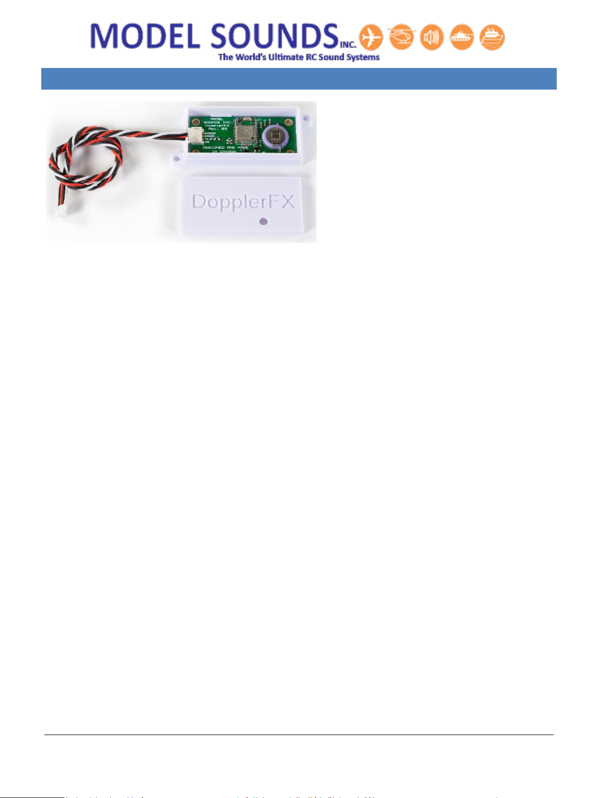
The Model Sounds Inc. DopplerFX feature is unique in the model RC world.
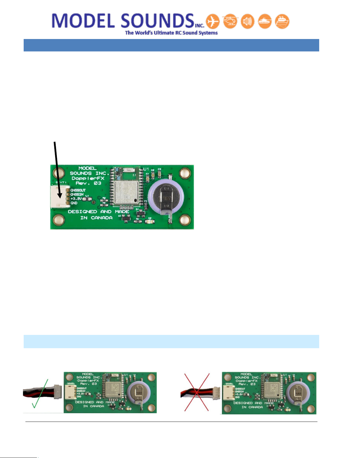
It is a feature of the ShockWave 3 sound module and is enabled by the DopplerFX accessory board
that communicates with the ShockWave 3 sound module using two signal wires. The DopplerFX
accessory board takes its +3.3 Volt power from the ShockWave 3 sound module over the same four
wire cable that provides the serial two wire data link.
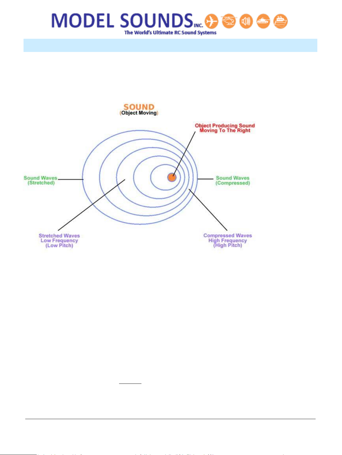
The concept of the DopplerFX feature is that it provides an enhanced Doppler frequency shift
experience to a ground observer while the model aircraft or helicopter is in flight. Doppler shift is the
change in pitch of a sound as the source gets closer, then gets further away, e.g. like an ambulance,
fire engine or police siren. Due to its own motion, every model aircraft produces its own natural
Doppler shift as it approaches towards and recedes from a stationary observer on the ground.
But because a scale model aircraft’s speed is fairly slow compared to the speed of sound, especially
when flown at a realistically slow scale speed, its natural Doppler shift is quite mild in effect. If the
model is outfitted with our ShockWave 3 sound system, this DopplerFX accessory board can provide
increased Doppler frequency shift to the engine and gunfire sounds played back by the sound module.
This can make the model sound as though it is travelling at 350km/hr when its actual speed is only
50km/hr, for example.
HOW DOES THE DOPPLERFX FEATURE WORK?
When the sound system is first powered up by the pilot, once a GNSS (e.g. GPS) satellite fix has been
acquired, the DopplerFX feature will record the accessory board’s position. This is called the Observer
Position. Then as the aircraft moves away from or towards the Observer Position, either on the
ground, or in the air, the DopplerFX accessory board continuously updates its position and altitude at
up to 10 times per second and the ShockWave 3 sound module will calculate its speed and position
relative to the Observer Position.
Then, depending on its speed and whether it is approaching towards, or receding from, the Observer
Position, the ShockWave 3 sound module will compute what the relative Doppler frequency shift
should be to simulate the plane’s actual speed multiplied by the Speed Multiplication Factor. It then
changes its playback speed appropriately.

DopplerFX®Rev. 03 Reference Manual Page 5 of 17 Published: January 20, 2021
© Model SoundsTM Inc.
SOME SIMPLE MATH THAT EXPLAINS DOPPLER FREQUENCY SHIFT
Doppler shift (in the light from stars) was first identified and named after the Austrian physicist
Christian Doppler, who described the phenomenon in 1842 and his theory was tested for sound waves
by the Dutch chemist Buys Ballot in 1845.
Doppler shift in
sound is a time
compression of
the sound
wavefronts
(wavelength
compression) due
to the source’s
motion.
V = f x λwhere
V = velocity
(speed of sound),
f = frequency, and
λis the
wavelength of the
sound.
Therefore f = V / λ and since V, the speed of sound, is constant, more or less, if the wavelength λ
decreases, as when the sound source is approaching you, then frequency f goes up.
Conversely if the wavelength λincreases, as when the sound source is receding from you, then
frequency f goes down.
And when the source is immediately at your location when it is nether approaching or receding f, the
frequency you hear, is the same as the source’s own frequency.
It is important to realize that, under normal circumstances, the source’s sound frequency does not
actually change at all. It is only due to the wavefront compression and stretching due to its motion that
the sound a fixed observer hears appears to change.
The DopplerFX feature implemented in the ShockWave 3 sound module enhances this natural effect
by applying additional frequency shift at the source to emulate a much higher speed.

DopplerFX®Rev. 03 Reference Manual Page 6 of 17 Published: January 20, 2021
© Model SoundsTM Inc.
WHAT IS GNSS?
GNSS is an acronym for Global Navigation Satellite System. This is a generic descriptor for Satellite
based navigation systems used worldwide. While the most commonly known of these is the U.S.
Department of Defence owned GPS (Global Positioning System), there are several other Satellite
Navigation (sometimes abbreviated SATNAV, especially in the U.K.) systems in use developed by other
countries.
In particular there is the Russian GLONASS system, the European GALILEO system, the Chinese BEIDOU
system and the Japanese QZSS system. The Japanese QZSS system uses a small number of satellites in
non-geo-synchronous orbits around the Japanese archipelago which work in conjunction with the U.S.
GPS satellites to give better coverage in many of the Japanese cities' concrete canyons.
The Model Sounds Inc. DopplerFX board has an on-board GNSS receiver that is capable of receiving all
of these GNSS satellite signals, although not all simultaneously.
The preferred Data update rate for smoothest operation of the DopplerFX features is 10 times per
second. However, the more satellite systems it has to listen to, the less frequently it is able to provide
updated position data.
The following table shows allowable GNSS Modes supported by the Model Sounds Inc. DopplerFX
board:
Table 1: Supported GNSS Receiver Modes
Supported GNSS Mode
Data Update Rate
GPS ONLY
10 times per second
GPS + GLONASS
5 times per second
GPS + GALILEO
5 times per second
GPS + BEIDOU
5 times per second
QZSS is automatically supported as QZSS satellites augment the GPS System. These various receiver
modes are selected in the DopplerFXSettings.txt file on the microSD card.

DopplerFX®Rev. 03 Reference Manual Page 7 of 17 Published: January 20, 2021
© Model SoundsTM Inc.
Caution About Using Other GNSS/GPS Receivers
The Model Sounds Inc. DopplerFX accessory board has been carefully engineered to give optimum
performance in all RC model aircraft applications, including model airplanes and model helicopters.
Although there are alternative products which, superficially, seem the same and are less expensive,
they almost always use what is known as a ceramic patch antenna.
These types of antennas are highly directional and therefore must point to the sky at all times. These
are therefore best suited to applications such as vehicle tracking, robots and multi-rotor drones which
stay parallel to the earth’s surface at all times.
Our DopplerFX board uses a ceramic chip antenna which is omni-directional and thus will not lose a
GNSS tracking signal when a model aircraft is rolling, climbing or diving.
In additional, the backup battery on-board the DopplerFX board is much larger than these alternative,
cheaper, products, and therefore will last a whole flying season without being charged, or between
flying seasons if stored in its charged state.
Finally, all of these alternative GNSS/GPS receivers have either no connector or have a different type
and/or size and/or different pinouts than those of the DopplerFX board which makes it very difficult or
impossible for the average modeller to make correct connections to the ShockWave 3 sound module.

DopplerFX®Rev. 03 Reference Manual Page 8 of 17 Published: January 20, 2021
© Model SoundsTM Inc.
CHAPTER 2 –MOUNTING THE DOPPLERFX ACCESSORY BOARD
The DopplerFX board is shipped mounted
inside its plastic case with the 4-wire cable
connected as shown here.
The lid will already be installed. If the cable
should become loose, the lid must be
removed in order to push the connector fully
home.
If you need to adjust the cable connector, remove the lid by gripping the case sides (not the lid sides),
pushing them in slightly and lifting off the lid. With the lid off it is much easier to fully insert the cable
plug into its connector on the board.
Then, replace the lid on top with the LED hole above the LED. Press the lid firmly home so that its
retention indents lock into the corresponding bumps on the case.
Use the supplied hook and loop fastener patch to attach the case, with the lid uppermost to the inside
top of your fuselage. Additional glue may be required to attach the hook and loop fastener securely to
your fuselage especially when it is left out in the sun and heats up.
In this way the GNSS antenna will be facing upwards and towards the sky when the model is flying level
the right way up.
Keep the DopplerFX Accessory board as far away as possible from all other electronics and metal or
carbon fibre structures as they can interfere with the very weak GNSS satellite signals.

DopplerFX®Rev. 03 Reference Manual Page 9 of 17 Published: January 20, 2021
© Model SoundsTM Inc.
CHAPTER 3 –HOW TO CONNECT YOUR DOPPLERFX ACCESSORY BOARD
The DopplerFX board comes pre-mounted inside a plastic case with its 4-wire cable already connected.
The other end of that cable should be firmly inserted into SCKT3 of the ShockWave 3 sound module.
Should the cable become disconnected from the DopplerFX board, please reconnect it as follows.
1. Remove the lid by gripping the case sides (not the lid sides), pushing them in slightly and lifting
off the lid. With the lid off it is much easier to fully insert the cable plug into its connector on
the board.
2. Insert the cable connector into the four pin 1.5mm pitch connector SCKT1.
Figure 1 - DopplerFX Accessory Board
Use ONLY the
4-wire accessory cable from Model
Sounds Inc. provided with the DopplerFX
board.
DO NOT connect the other end of the accessory cable to anywhere other than the accessory port of
the ShockWave 3 sound module.
When connecting the 4-wire accessory cable to the DopplerFX board make sure the connector on the
cable is inserted into the board connector the right way up. The white wire should always be to the top
of the board. The connector is quite stiff, so make sure it is inserted all the way in.
If you need to remove it, do so very carefully by teasing the plug from its socket with a finger or
thumbnail or a small screwdriver. Do not pull on the wires to remove it as they will be pulled out of
the plug.
ORIENTATION OF THE 4-WIRE ACCESSORY CABLE CONNECTOR ON DOPPLERFX BOARD
Figure 2 - Correct Position of 4-Wire Connector Figure 3 - Incorrect Position of 4-Wire Connector

DopplerFX®Rev. 03 Reference Manual Page 10 of 17 Published: January 20, 2021
© Model SoundsTM Inc.
ORIENTATION OF THE 4-WIRE ACCESSORY CABLE CONNECTOR ON SHOCKWAVE 3 BOARD
Correct Orientation of 4-Wire Connector On ShockWave 3 Incorrect Orientation of 4-Wire Connector
When connecting the 4-wire accessory cable to the ShockWave 3 board, make sure the connector on
the cable is inserted into the board connector the right way up. The white wire always goes to the top
edge of the board connector as shown here. The connector is quite stiff, so make sure it is inserted all
the way in.
If you need to remove it, do so very carefully by teasing the plug from its socket with a finger or
thumbnail. Do not pull on the wires to remove it as they will be pulled out of the plug.
POWERING THE DOPPLERFX ACCESSORY BOARD
The DopplerFX Accessory board requires +3.3Volts power AND NO HIGHER. This power is drawn from
the ShockWave 3 sound module’s on-board +3.3V voltage regulator through the provided four-wire
cable connecting the DopplerFX Accessory board to the ShockWave 3 module.
This same power provides charging current for the on-board re-chargeable coin-cell backup battery.
When it is first received, it is advisable to power up the DopplerFX board through the ShockWave 3
board for a period of 24 hours to charge up its rechargeable coin-cell backup battery.
It is not necessary to apply power to the ShockWave 3’s blue terminal block for this.

DopplerFX®Rev. 03 Reference Manual Page 11 of 17 Published: January 20, 2021
© Model SoundsTM Inc.
CHAPTER 4 –HOW TO OPERATE YOUR DOPPLERFX ACCESSORY BOARD
RC INPUTS ON THE SHOCKWAVE 3 MODULE SUPPORTING THE DOPPLERFX FEATURE
The ShockWave 3 sound module has a set of SOUND3 RC input pins on its HEADER1 (at the bottom left
hand side of the board).
Pins 1, 2, 3 on that HEADER1 is configured by default to support an optional input from a spare RC
receiver channel to control the DopplerFX feature. This input can be used to both reset the Observer
Position (more later) and to remotely enable and disable the DopplerFX feature.
Pin 1 is system GND, or battery –ve, pin 2 is receiver power, pin 3 carries the DopplerFX RC receiver
signal from the radio receiver into the ShockWave 3 board.
To use this input effectively, it should be used with a three-position switch on your radio with the
centre position being the OFF position. One direction is used to reset the Observer Position
(more later) and the other direction is used to remotely enable and disable the DopplerFX feature.
SETTING THE OBSERVER POSITION REMOTELY
The Observer Position is always recorded when the system is first powered up and once the GNSS
satellite fix has been obtained. While in flight, the Doppler frequency shift is always computed relative
to the Observer Position. This may not be what the pilot wants, especially if the pilot station is some
distance away from the start-up pits or wherever the plane’s electronics were first switched on.
Also, if the pilot is trying to impress the judges in a scale model competition, he may want to reset the
Observer Position to a point near the judges so that they experience the proper Doppler shift
enhancement.
The Observer Position can be reset remotely using the ShockWave 3 SOUND3 RC input. This is optional
and, if connected, it should be controlled by a three-position switch on the Transmitter. This radio
channel’s OFF position pulse width is measured when the ShockWave 3 board is powered up.
When the 3-position switch is thrown causing the input pulse width to be different by more than
+100us from this initial value, the Observer Position will be reset to wherever the plane currently is.
After setting the Observer Position this way, the switch should be returned to its previous OFF
position.

DopplerFX®Rev. 03 Reference Manual Page 12 of 17 Published: January 20, 2021
© Model SoundsTM Inc.
ENABLING/DISABLING THE DOPPLERFX FEATURE
The pilot may not always want the enhanced Doppler Shift feature on all the time. The ShockWave 3
SOUND3 RC input can be used to enable or disable the feature remotely. When disabled, the motion
tracking and all computations relative to the Observer Position will continue but there will be no
frequency shift in the played back sounds. This is useful to demonstrate he effectiveness of the
DopplerFX feature.
With the switch in its initial centre position, the Doppler Enhancement feature is enabled and the
Observer Position is setup when the system is powered up. If the 3-position switch is moved to the
other extreme where the input pulse width is different by more than -100us from its initial value, the
Doppler Enhancement feature is disabled until the switch is released back to its centre position.
THE DOPPLERFX LED INDICATOR
The DopplerFX Accessory board has a dual-purpose Green LED. The Green LED will light steadily when
power is first applied to the board. Once a satellite fix is obtained it will flash on and off once per
second as a satellite fix acquired indicator.
However, since the DopplerFX board is installed inside the model, this LED is of little use to the user, so
there needs to be an external mechanism to indicate when a satellite fix has been obtained.
RANGE OF DOPPLER SHIFT ENHANCEMENT
The ShockWave 3 sound module can accommodate an increase or decrease in playback speed by up to
two times. When applying that number to the standard Doppler shift formula, this represents a
maximum simulated speed of 615 km/hr (384 mph) or Mach 0.5.

DopplerFX®Rev. 03 Reference Manual Page 13 of 17 Published: January 20, 2021
© Model SoundsTM Inc.
CHAPTER 5 –THE DOPPLERFXSETTINGS.TXT FILE
Important settings for the DopplerFX feature are contained in a DopplerFXSettings.txt text file on the
microSD card. This file is mandatory. If it is missing, the ShockWave 3 sound module will create one
with default values as below:
DopplerFXSettings.txt File Default Contents
The DopplerFXSettings.txt File looks like this:
**** DopplerFXSettings.txt ****
// SatelliteConstellations: can be one of GPS_ONLY, GPS_PLUS_GLONASS, GPS_PLUS GALILEO,
GPS_PLUS BEIDOU
SatelliteConstellations: GPS_ONLY
// DopplerFXSpeedMultiplier: can be one of 1,3,5,7
DopplerFXSpeedMultiplier: 7
// The following can all have values of yes or no.
// If the OnceOnly settings are yes, that means the sound is played only the first time that event occurs.
// If the OnceOnly settings are no, that means the sound is played every time that event occurs.
PlaySatelliteFixAcquiredLostSounds: yes
PlaySatelliteFixAcquiredLostSoundsOnceOnly: no
PlayObserverPositionSetSounds: yes
PlayObserverPositionSetSoundsOnceOnly: no
PlayDopplerFXEnabledDisabledSounds: yes
PlayDopplerFXEnabledDisabledSoundsOnceOnly: no
The field names are mostly self-explanatory.
Field names must be EXACTLY as shown here and are case sensitive.
Data values can be yes or no and can be upper or lower case.
Comment lines start with //

DopplerFX®Rev. 03 Reference Manual Page 14 of 17 Published: January 20, 2021
© Model SoundsTM Inc.
CHAPTER 6 - HOW DO I KNOW WHEN I HAVE A SATELLITE FIX?
When first powered up or when powered up a long distance from when it was previously powered, the
“satellites in view” may be different and the time to get the first position fix may be as long as 1
minute or so. This time is called the Time To First Fix (TTFF). Under these circumstances it is called a
“cold start”.
Subsequently, as long as the backup battery is charged, and if you power-up the ShockWave 3 and
DopplerFX board in roughly the same location as last time, this time will be less than 10 seconds. This
is called a “hot-start”.
THE EFFECTS OF WEATHER ON THE TIME TO FIRST FIX
GNSS satellites broadcast their signals to earth at microwave frequencies around 1.6GHz. At these
frequencies, the radio waves can easily be absorbed by water molecules such as those present in
clouds in the atmosphere. This makes it more difficult for the GNSS receiver to acquire the satellite
signals and determine its location.
Therefore, the TTFF may be longer on cloudy days compared to sunny, bright and cloudless days.
USING SYSTEM SOUNDS FOR DOPPLERFX EVENT NOTIFICATIONS
The ShockWave 3 module can make system sound announcements to notify you of events such as
Satellite Fix Acquired or Lost, Observer Position Set and some others. These system sound
announcements can be turned on and off by the user using text entries in the DopplerFXSettings.txt
file on the microSD card. They can also be changed in the ShockWave 3 PC software
Control Panel->DopplerFX Tab.
DopplerFX Notification Sounds depend on System Sounds being Enabled on the ShockWave 3.
For those fields whose values are “yes”, the sounds will only play if System Sounds are enabled on the
ShockWave 3 module using Button1. It is therefore highly recommended to have System Sounds
enabled to start with, when first operating the model with the DopplerFX board. Then, once you have
got used to how it behaves, you can turn System Sounds OFF.

DopplerFX®Rev. 03 Reference Manual Page 15 of 17 Published: January 20, 2021
© Model SoundsTM Inc.
CHAPTER 7 –THE DOPPLERFX BOARD BACKUP BATTERY
When a GNSS receiver is first powered up it does a “Cold Start”. This means that it searches for
available satellites and builds a small database of available start-up information and other essential
data. If there is a backup battery present, this start-up information is stored in volatile memory (RAM)
that would otherwise be lost when its main power is removed, as when the electric power system in
the model is switched off.
Since a cold start can take up to 2 minutes or more to perform, by storing the information in backup
memory, it can perform a “Warm Start” next time which takes only 10 seconds. The current drain
when in backup mode is only about 7uA and the 3V coin-cell will last about 2430 hours (about 101
days) without being recharged. It will likely run down during the winter months when the plane is not
in use and will start-up again in Cold Start mode the first time it is powered up in the next flying
season.
It is recommended to charge up the battery at least twice during the winter months. The battery gets
charged automatically when the main +3.3V power from the ShockWave 3 sound module is applied.
Care should be taken to NOT short circuit the small coin-cell backup battery with stray tools or wires.

DopplerFX®Rev. 03 Reference Manual Page 16 of 17 Published: January 20, 2021
© Model SoundsTM Inc.
CHAPTER 8 –LIMITATIONS
Since the Doppler frequency shift is calculated relative to the Observer Position, the correct frequency
shift will be observed only by someone at that position. If the plane is being flown at a large show with
a long flight line, most of the people along that flight line will observe the frequency shift from
Increasing to Decreasing at the Observer Position which is other than where they are standing. This
may sound a bit strange.
The amount of available frequency shift is limited to about 2 times faster or slower than the regular
playback rate.
Frequency Shift Limits
Two times faster is achieved when the simulated speed is 615 km/hr (384 mph) or Mach 0.5, so if the
speed multiplier is set at the maximum of 7 times, the actual model speed would be 88 km/hr (55
mph). Of course, the model can travel faster than that, but the enhanced Doppler frequency shift will
max. out at those speeds. If you have a faster flying model then consider reducing the Model Speed
Multiplier to 3 times, instead of the maximum 7 times.
Even if the model’s actual speed multiplied by the Speed Multiplication Factor is greater than this
speed, the maximum shift will be limited to 2 times so the Doppler Shift will not change while the
simulated speed is greater than the above figure.
Doppler Shift Enhancement Effect is Model Dependent
The perceived Doppler shift, both with and without the DopplerFX feature running, is dependent upon
the actual sound playing, depending on its tonal content, i.e. mix of different frequency sounds.
Some aircrafts, jets and helicopters sound better than others.

DopplerFX®Rev. 03 Reference Manual Page 17 of 17 Published: January 20, 2021
© Model SoundsTM Inc.
INDEX
Caution About Using Other GNSS/GPS
Receivers....................................................... 7
Doppler Shift Enhancement Effect is Model
Dependent .................................................. 16
DopplerFX Accessory Board Connections......... 9
Enabling/Disabling The DopplerFX Feature.... 12
Frequency Shift Limits..................................... 16
How Does The DopplerFX Feature Work?........ 4
Initial Start Point ............................................... 4
Limitations ...................................................... 16
Orientation of the 4-Wire Accessory Cable
Connector ..................................................... 9
Powering the DopplerFX Accessory Board ..... 10
Purpose of the DopplerFX Board ...................... 4
R/C Inputs on the ShockWave 3 Module
Supporting the DopplerFX Feature............. 11
Range of Doppler Shift Enhancement............. 12
Setting The Observer point Remotely ............ 11
ShockWave 3 sound module............................. 4
Some Simple Doppler Shift Math That Explains
Doppler Frequency Shift ............................... 5
The DopplerFXSettings.txt File........................ 13
The Effects of Weather on the Time To First Fix
..................................................................... 14
Using LEDs for Satellite Fix Acquired/Observer
Position Set Notifications............................ 12
Other manuals for DopplerFX
1
Table of contents
Other MODEL SOUNDS Recording Equipment manuals