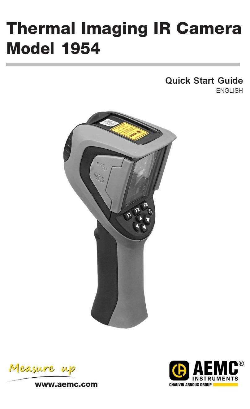
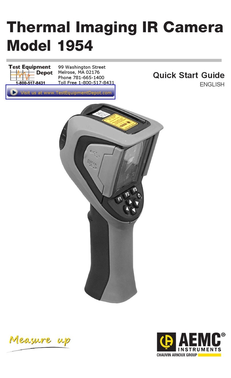
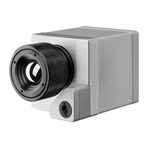
AEMC instruments 1954 User manual

WITH AEMC
®
INSTRUMENTS
THERMAL IMAGING CAMERAS
Thermal Imaging
IR Camera
Model 1954
ENGLISH
User Manual

Copyright©Chauvin Arnoux®, Inc. d.b.a. AEMC®Instruments. All rights reserved.
No part of this documentation may be reproduced in any form or by any means (including electronic
storage and retrieval or translation into any other language) without prior agreement and written consent
from Chauvin Arnoux®, Inc., as governed by United States and International copyright laws.
Chauvin Arnoux®, Inc. d.b.a. AEMC®Instruments
15 Faraday Drive • Dover, NH 03820 USA
Tel: (800) 945-2362 or (603) 749-6434 • Fax: (603) 742-2346
This documentation is provided “as is,” without warranty of any kind, express, implied, or otherwise.
Chauvin Arnoux®, Inc. has made every reasonable eort to ensure that this documentation is accurate;
but does not warrant the accuracy or completeness of the text, graphics, or other information contained
in this documentation. Chauvin Arnoux®, Inc. shall not be liable for any damages, special, indirect,
incidental, or inconsequential; including (but not limited to) physical, emotional or monetary damages
due to lost revenues or lost prots that may result from the use of this documentation, whether or not the
user of the documentation has been advised of the possibility of such damages.

Chauvin Arnoux®, Inc.
d.b.a AEMC®Instruments
www.aemc.com
Statement of Compliance
Chauvin Arnoux®, Inc. d.b.a. AEMC® Instruments
certies that this instrument has been calibrated
using standards and instruments traceable to
international standards.
We guarantee that at the time of shipping your
instrument has met the instrument’s published
specications.
An NIST traceable certicate may be requested
at the time of purchase, or obtained by returning
the instrument to our repair and calibration
facility, for a nominal charge.
The recommended calibration interval for this
instrument is 12 months and begins on the date of
receipt by the customer. For recalibration, please
use our calibration services. Refer to our repair and
calibration section at www.aemc.com/calibration.
Serial #:
Catalog #: 2121.41
Model #: 1954
Please ll in the appropriate date as indicated:
Date Received:
Date Calibration Due:

4 Thermal Imaging IR Camera Model 1954 - User Manual
TABLE OF CONTENTS
1. INTRODUCTION..................................................................7
1.1. PRECAUTIONS FOR USE........................................................ 8
1.2. RECEIVING YOUR SHIPMENT............................................... 8
1.3. ORDERING INFORMATION.................................................... 9
1.3.1. Accessories & Replacement Parts .................................... 9
2. GETTING STARTED ......................................................... 10
2.1 BATTERY INSTALL ATION ...................................................... 10
2.2 MICRO SD MEMORY CARD INSTALLATION ...................... 11
2.3 CAMER A D IS PL AY.................................................................. 12
2.3.1 Main Screen ..................................................................... 12
2.3.1.1 Status Bar .................................................................................... 12
2.3.1.2 Image........................................................................................... 14
2.3.1.3 Measurements Display................................................................ 14
2.3.1.4 Function Buttons (F1, F2, and F3)............................................... 14
2.4 CONFIGURING THE CAMERA.............................................. 16
2.4.1 Languages ........................................................................ 17
2.4.2 Date and Time.................................................................. 17
2.4.3 Units of Measure (Temperature and Distance) ................ 18
2.4.4 Trigger Function................................................................ 18
2.4.5 Automatic Camera Shutdown Time.................................. 19
2.4.6 Screen Brightness............................................................ 19
2.4.7 Image Storage Directory .................................................. 20
2.4.8 Color Palettes................................................................... 21
3. BASIC OPERATION .........................................................22
3.1 MEASUREMENT CURSOR .................................................... 22
3.1.1 Estimating Measurements Without a Cursor .................... 22
3.1.2 Locating Hot and Cold Spots in an Image (MinMax)........ 23
3.1.3 Measuring Temperature at a Point in the Image (Point) ... 23
3.1.4 Measuring Temperatures of a Zone in the Image (Area) .. 23
3.1.5 Displaying the Temperature Prole of a Line in the Image
(Prole) ...................................................................................... 23
3.1.6 Displaying Points at the Same Temperature in an Image
(Isotherm) .................................................................................. 23
3.2 FREEZING PALETTE COLORS............................................. 24

Thermal Imaging IR Camera Model 1954 - User Manual 5
4. ADVANCED OPERATION................................................25
4.1 BEST PRACTICES................................................................... 25
4.2 COMPENSATING FOR INFLUENCING PARAMETERS ..... 25
4.2.1 Default Compensation Settings ........................................ 26
4.2.2 Custom Compensation Settings....................................... 26
4.3 TRIPOD..................................................................................... 27
5. SAVING AND RECALLING IMAGES ..............................28
5.1 IMAGE FILES ........................................................................... 28
5.1.1 Naming Conventions......................................................... 28
5.1.2 Directories......................................................................... 28
5.2 SAVING AN IMAGE ................................................................. 29
5.3 VOCAL MESSAGE .................................................................. 30
5.3.1 Creating a Vocal Message ............................................... 30
5.3.2 Changing the Vocal Message for an Existing Image ....... 31
5.4 RECALLING AN IMAGE.......................................................... 32
5.4.1 Derived Files from Recalled Images................................. 33
5.5 DELETING AN IMAGE ............................................................ 33
5.6 DOWNLOADING IMAGES TO A COMPUTER...................... 34
5.6.1 Downloading Directly from the Micro SD Memory Card... 34
5.7 CAMREPORT IMAGE ANALYSIS AND REPORT
GEN ER ATION ................................................................................ 34
6. SETUP FILES .................................................................... 35
6.1 CREATING A SETUP FILE ..................................................... 35
6.2 RECALLING A SETUP FILE ................................................... 36
6.3 DELETING A SETUP FILE...................................................... 36
6.4 RESTORING ORIGINAL DEFAULT SETTINGS ................... 36
7. BLUETOOTH..................................................................... 37
7.1 BLUETOOTH ACTIVATION/DEACTIVATION ........................ 37
7.1.1 Activating Bluetooth........................................................... 37
7.1.2 Deactivating Bluetooth ...................................................... 37
7. 2 H E A D S E T ................................................................................. 37
7.2.1 Headset Connection ......................................................... 38
7.2.1.1 First Time Connection.................................................................. 38
7.2.2 Changing Headsets .......................................................... 38
7.2.3 Headset Disconnection .................................................... 39

6 Thermal Imaging IR Camera Model 1954 - User Manual
7.3 MEASUREMENT DEVICES.................................................... 39
7.3.1 Peripheral Connection ...................................................... 40
7.3.2 Replacing Devices............................................................ 41
7.3.3 Device Polling Period........................................................ 41
7.3.4 Device Measurements Display ......................................... 41
7.3.5 Using a Measurement to Compensate for Environmental
Factors....................................................................................... 43
8. FIRMWARE UPDATES .....................................................44
9. TROUBLESHOOTING ......................................................45
9.1 IR IMAGE IS A SINGLE SOLID COLOR ................................ 45
9.1.1 Color Palette Frozen ......................................................... 45
9.1.2 Inconsistent User Inuencing Parameters ........................ 45
9.2 CONTRAST OF IR IMAGE IS INCORRECT ......................... 45
9.3 UNABLE TO SAVE DISPLAYED IMAGE............................... 45
9.4 SLOW OPENING OF FILES.................................................... 45
9.5 HEADSET CANNOT CONNECT TO CAMERA..................... 46
9.6 BLUETOOTH DEVICE CANNOT CONNECT TO CAMERA 46
10. MAINTENANCE............................................................... 47
10.1 CAMERA CLEANING ............................................................ 47
10.2 INFRARED OPTICS CLEANING ......................................... 47
10.3 REPAIR AND CALIBRATION................................................ 47
10.4 TECHNICAL ASSISTANCE................................................... 48
10.5 LIMITED WARRANTY........................................................... 48
10.5.1 Warranty Repairs............................................................ 49
APPENDIX A: MENU TREE .................................................50
APPENDIX B: EMISSIVITY TABLE ....................................52
APPENDIX C: TECHNICAL SPECIFICATIONS.................54

Thermal Imaging IR Camera Model 1954 - User Manual 7
1. INTRODUCTION
Do not aim the camera at the sun or other sources of powerful
thermal radiation.
Thank you for purchasing an AEMC®Instruments Thermal Imaging IR Camera
Model 1954.
For the best results from your instrument and for your safety, you must read the
enclosed operating instructions carefully and comply with the precautions for use.
Only qualied and trained operators should use this product.
Symbols and Denitions
CAUTION - Risk of Danger! Indicates a WARNING. Whenever this symbol
is present, the operator must refer to the user manual before operation
WARNING! Class 2 laser radiation (output <1 mW, wavelength 645 – 655
nm). If the ap is open, do not look into the beam
Indicates Important information to acknowledge
This product complies with the Low Voltage & Electromagnetic Compatibility
European directives
The UKCA marking certies that the product is compliant with the
requirements that apply in the United Kingdom, specically regarding
Low-Voltage Safety, Electromagnetic Compatibility, and the Restriction of
Hazardous Substances.
The product has been declared recyclable
In the European Union, this product is subject to a separate collection
system for recycling electrical and electronic components in accordance with
directive WEEE 2012/19/EU

8 Thermal Imaging IR Camera Model 1954 - User Manual
1.1. PRECAUTIONS FOR USE
■Never aim the camera at the sun or other strong source of thermal
radiation. This can impair camera operation and/or damage its infrared
sensor. To avoid accidental exposure, close the lens ap when the camera is
not in use.
■Avoid exposure to dust with the lens ap open. Dust on the lens can
absorb thermal ux and cause articial diusion. It can also degrade image
sharpness. To clean the lens, refer to § 10.2.
■Do not touch the lens with your ngers. Acids from human skin can
damage the lens and its coatings.
■Avoid jolting or dropping the camera.
■Do not point the camera’s laser pointer at a person’s eyes. This can result
in burns and other damage to the eyes.
■Caution! Observe all safety warnings! Use of controls or adjustments,
or performance of procedures, other than those specied herein, may
result in hazardous radiation exposure.
1.2. RECEIVING YOUR SHIPMENT
Upon receiving your shipment, make sure that the contents are consistent with
the packing list. Notify your distributor of any missing items. If the equipment
appears to be damaged, le a claim immediately with the carrier and notify
your distributor at once, giving a detailed description of any damage. Save the
damaged packing container to substantiate your claim.

Thermal Imaging IR Camera Model 1954 - User Manual 9
1.3. ORDERING INFORMATION
Thermal Imaging IR Camera Model 1954...................................... Cat. #2121.41
Incudes carrying case, external battery charger, USB cable, four NiMh
rechargeable batteries, micro SD card with adaptor, Bluetooth headset, quick
start guide, and a USB drive containing the user manual, CAmReport software,
and software manual.
1.3.1. Accessories & Replacement Parts
Case – Carrying Case with Foam Insert.......................................... Cat. #2121.60
Adapter - US External Battery Charger ........................................... Cat. #2121.64
Cable – USB (Type A to 5-pin Mini-B) .............................................Cat. #2126.49
The rechargeable batteries supplied with the camera can be charged with any
commercially available AA charger.

10 Thermal Imaging IR Camera Model 1954 - User Manual
2. GETTING STARTED
2.1 BATTERY INSTALLATION
The camera accepts four AA batteries, alkaline or NiMH rechargeable. The latter
can be recharged with an external charger supplied with the camera.
When the batteries are removed, the internal clock has sucient power for 15 h.
The batteries are inserted through the end of the handle. Open the cover using a
coin while pressing down on the locking tab:
2.1.1 Battery Management
The Battery management menu appears
when the batteries have been removed. If
you insert fully-charged batteries, advanced
management allows more options.
After the batteries are installed or replaced, the
Battery management menu appears when the
camera rst starts up. This menu can also be
displayed by pressing and holding down the
F2 button when the camera is powered ON.
In the Battery management menu, the
function buttons perform the following:
F1 conrms the information entered
closes the window, and initializes the settings
F2 edits and conrms entry of the
selected item
F3 cancels an entry or closes the window
without resetting the battery options

Thermal Imaging IR Camera Model 1954 - User Manual 11
The battery management menu can operate in one of two modes.
Advanced O (Default) is display-only; you cannot change any settings in this
mode. In default mode, the battery icon only appears when battery power is low.
When this icon appears, the camera will operate for approximately 30 minutes
and then shut down automatically.
Advanced On allows more precise tracking of battery energy consumption,
including the type of batteries used and their estimated capacity. In Advanced
mode, the battery icon indicates how much charge is left in the batteries. Initially
this icon is green: . When the remaining charge is low this icon appears
yellow: . When 30 minutes of charge remains, this icon appears as .
To change mode, ensure the Advanced icon is selected. If not, use the arrow
buttons to select it. Press to edit the setting, and use the up and down
buttons to change the setting to the desired option. Then press to conrm the
change.
Type of batteries: The camera is delivered with low-self-discharge NiMH
rechargeable batteries with a capacity of approximately 2500 mAh. These are the
default parameters.
NOTE: If you consistently use the same set of rechargeable batteries,
we recommend operating the camera until it automatically switches
OFF due to low batteries. This automatically recalculates and adjusts
the estimated capacity of the batteries. The new capacity is displayed
by default the next time the Battery management menu is displayed.
2.2 MICRO SD MEMORY CARD INSTALLATION
Camera les (images, audio, and
setup) are stored in the micro SD
memory card located on the left side
of the head (see photo below). If this
card is not installed, an error message
appears when the camera attempts to
access it. This card is provided with
the camera.
Before installation, the memory card
must be formatted in one of the
following formats:
■FAT16
■FAT32
To insert the card, open the rubber
ap and push the card into the
SD card slot. If the card cannot be
inserted, ensure that:
■The card is facing in the correct
direction
■The card slot is empty

12 Thermal Imaging IR Camera Model 1954 - User Manual
2.3 CAMERA DISPLAY
In normal operation, the camera starts up:
■at the Main screen (see below)
■in continuous acquisition mode
■with the conguration setup loaded when it was last turned OFF
2.3.1 Main Screen
The Main screen is organized as shown in the below illustration:
2.3.1.1 Status Bar
Normal operation:
Battery (§ 2.1.1)
no icon (Default Battery Management mode only) Batteries OK
(Advanced Battery Management mode only) Batteries OK
(Advanced Battery Management mode only) Batteries low
(Both modes) Batteries discharged
Bluetooth (§ 7)
Bluetooth enabled
no icon Bluetooth enabled
Trigger Function (§ 2.4.4)
TAAim
TFFreeze
TSSave
TLLater

Thermal Imaging IR Camera Model 1954 - User Manual 13
Micro SD Card (§ 2.2)
Micro SD Card detected
Micro SD Card not detected
Emissivity correction (§ 4.2)
User-dened correction in eect
Default correction in eect
Date/Time (§ 2.4.2)
Date and time of acquisition of the displayed image
Acquisition Default
Continuous acquisition
Acquisition stopped (image frozen
Status bar icons appear as follows when an image is recalled from memory and
displayed:
Battery (§ 2.1.1)
no icon (Default Battery Management mode only) Batteries OK
(Advanced Battery Management mode only) Batteries OK
(Advanced Battery Management mode only) Batteries low
(Both modes) Batteries discharged
Bluetooth (§ 7)
Bluetooth enabled
no display Bluetooth enabled
Trigger Function (§ 2.4.4)
TA Aim
Image Recall (§ 5)
Micro SD Card detected
Micro SD Card not detected
Emissivity correction (§ 4.2)
no icon User-dened correction in eect
Default correction in eect
Image Filename (§ 5.1.1)
Date and time of acquisition of the displayed image

14 Thermal Imaging IR Camera Model 1954 - User Manual
2.3.1.2 Image
The central part of the Main screen displays the image. This can be either
infrared (thermogram) or visible light. At the bottom of the image area is the
color palette. This identies the temperatures represented by the colors in
the thermogram. (The colors used to create the thermogram are dened by
the selected palette, see § 2.4.8) By default, temperature/color assignment
is performed automatically as a function of the minimum and maximum
temperatures detected in the image. In this mode the palette appears as follows
(in this example the steel palette is selected):
You can also freeze the palette by dening minimum and maximum temperatures
(see § 3.2). When the palette is frozen, it appears as follows:
2.3.1.3 Measurements Display
Below the image area the Main screen displays the temperature measurement
for the point or region in the image dened by the cursor(s). If there is sucient
space, this area also shows the measurement(s) detected by the
AEMC®Instruments compatible meter(s) (if any) connected to the camera via
Bluetooth (see § 7.3).
2.3.1.4 Function Buttons (F1, F2, and F3)
The camera includes three function buttons, labelled F1, F2, and F3. The
functions performed by these buttons depend on the camera mode. The current
function for each button is identied by an icon that appears on the display
screen just above the button. If no button is pressed for 5 seconds, the function
icons disappear and are replaced by a small uparrow above F2.
Pressing a button restores the function icons.
Several icons represent multiple tasks, depending on mode:
Opens the Main conguration menu
Re-opens the last menu opened
Closes all open menus
Selects the highlighted item
Closes a message
Adds the selected character
Closes a menu
Cancels an entry
Freezes the image
Restarts continuous acquisition (unfreezes image)
Saves the displayed image

Thermal Imaging IR Camera Model 1954 - User Manual 15
Validates the entry in the text editor or the selection in the working
directory
Deletes the selected le or folder
Opens the selected le or folder
Exits from image recall
Displays information from the selected le
Freezes the color palette
Edits the minimum or maximum value of the palette
Restores automatic mode
Displays the infrared image
Displays the visible image
Plays back the vocal message
Records a new vocal message
Stops playing or recording the vocal message
Searches for new Bluetooth devices (AEMC®Instruments Clamp-On
Meters Models 407 and 607, Metrix ASYC IV Multimeters Models MTX
3292-BT and 3293-BT, Environmental Data Loggers Models 1110,
1227, 1246, 1821, 1822 and 1823)
Connects all compatible Bluetooth AEMC®Instruments meters in the
current list
Lights the laser pointer
Restores function icons display

16 Thermal Imaging IR Camera Model 1954 - User Manual
2.4 CONFIGURING THE CAMERA
When the camera is rst started up, all parameters are set to their default values.
You can modify these settings. The changes can be stored in the camera’s
memory; these settings will then be used every time the camera is subsequently
turned ON. Note that conguration settings can be saved in a Setup le. This le
can then be recalled and applied (see § 6).
To enter conguration mode, press
F1 in the Main screen. This displays
the Main conguration menu. This screen
provides six options. Each displays a
submenu:
■Display sets options that control how the
display of data appears on the camera
screen.
■Files displays options for storing, recalling,
and working with images and other les.
■Setup saves and recalls conguration les.
■Target sets parameters associated with
the camera’s target, such as distance and
temperature.
■Parameters congures camera settings
such as language, date/time, and others.
■About displays information about the
camera.
Use the camera’s arrow buttons to navigate through the menu options. Selected
options appear highlighted in yellow. (See Appendix A for the camera’s complete
conguration menu tree.)
In conguration mode, the function buttons perform the following:
F1 closes all open menus without action, and returns to the
Main screen
F2
either:
■opens the corresponding sub-menu
■(for editable settings) modies the selected parameter
F3 closes the current window without action, and returns to the
previous menu or screen
When an editable parameter is selected, it appears on a blue background with
the symbol to the left. This symbol allows you to view available options,
which you can scroll through using the up and down buttons. After you select an
option, press F2 to accept it.
NOTE: That the parameters that cannot be modied appear shaded.

Thermal Imaging IR Camera Model 1954 - User Manual 17
2.4.1 Languages
To change the language in which the camera menus appear:
1. In the Main screen, press F1 to
display the Main conguration menu.
2. Use the arrow buttons to highlight
Parameters, and then press F2 to
display the Parameters menu.
3. Select Adjustments and press F2 to
display the Adjustments menu (shown to
the left).
4. Select Languages to display a list of
available languages.
5. Use the up and down buttons to scroll
through the available languages. When
the desired language is highlighted, press
F2 . All menus will now appear in the
selected language.
2.4.2 Date and Time
Accurate date and time data is critical for correct camera operation. For example,
by default les stored in the camera are named with date and time information
(see § 5.1). To set the date and time:
1. In the Main screen, press F1 to display the Main conguration menu.
2. Highlight Parameters and then press F2 to display the Parameters
menu.
3. Select Adjustments and press F2 to display the Adjustments menu.
4. Select Date/Time and press F2 to display the Date/Time menu.
5. Use the left and right navigation buttons to select the parameters to modify.
6. To edit a selected setting, press F2 and use the up and down buttons to
change the setting.
7. Press F2 to save the setting.
8. When all settings have been selected, select Validate and press F2 .
NOTE: The Date/Time menu opens automatically at start-up if power to
the internal clock has been interrupted.

18 Thermal Imaging IR Camera Model 1954 - User Manual
2.4.3 Units of Measure (Temperature and Distance)
1. Open the Adjustments menu by pressing F1 in the Main screen and
selecting Parameters > Adjustments.
2. Select to display the units in which temperature and distance are
displayed:
Temperature: Fahrenheit (°F) or Celsius (°C). Default is Fahrenheit.
Distance: Foot (ft) or Meter (m). Default is Foot.
3. Select the desired units and press F2 to save the settings.
2.4.4 Trigger Function
The camera trigger can be congured to perform dierent tasks when pressed.
1. Open the Adjustments menu by pressing F1 in the Main screen and
selecting Parameters > Adjustments.
2. Select Trigger to display the Trigger menu. This lists the following
options.
Aim (the default) congures the trigger to toggle the display from
the infrared image to the visible camera image. The laser lights when the
trigger is pressed. When this option is selected, the TA icon is displayed
in the status bar at the top of the screen. When an image is recalled, the
trigger is automatically assigned this function. When you exit the recalled
image, the user-selected function is restored.
Freeze congures the trigger to stop the continuous updating of the
display and freeze the image. Both the infrared and visible images are
frozen; you can toggle between them by pressing F3. When this option is
selected, the TF icon is displayed in the status bar. Pressing the trigger
again restarts continuous acquisition.
Save congures the trigger to freeze the infrared and visible
images, and then record them on the micro SD card (if one is present).
When this option is selected, the TS icon is displayed in the status bar.
Each press results in another save, creating derivative les if image
acquisition is not restarted between presses. To restart continuous
acquisition, press F2 and then press F2 again.
Laser congures the trigger to turn ON the laser pointer when the
trigger is depressed. Releasing the trigger turns OFF the pointer. When
this function is selected, the TL icon is displayed in the status bar.

Thermal Imaging IR Camera Model 1954 - User Manual 19
2.4.5 Automatic Camera Shutdown Time
To save battery power, the camera automatically turns OFF after a period of
inactivity. The duration of this period can be set to between 15 (default) and 60
minutes. This feature can also be disabled. To change this setting:
1. Open the Adjustments menu by pressing F1 in the Main screen and
selecting Parameters > Adjustments.
2. Select to display the shutdown time setting.
3. Use the up and down buttons to change settings. You can also select None
to disable automatic shutdown. When None is selected, the camera turns o
only when battery power is too low to continue operation.
4. When the desired setting is displayed, press F2 .
2.4.6 Screen Brightness
You can adjust the screen brightness level to ensure good visibility in varying
lighting conditions. By default, the camera is congured in Automatic mode: a
brightness sensor adjusts the lighting level at all times. To change this:
1. Open the Adjustments menu by pressing F1 in the Main screen and
selecting Parameters > Adjustments.
2. Select to display the screen brightness setting. Use the up and
down buttons to change this setting. Options are Automatic (the camera
automatically adjusts the screen brightness), or a percentage of full screen
brightness (15 %, 25 %, 50 %, 75 %, or 100 %).
3. When the desired setting is displayed, press F2 to select it.

20 Thermal Imaging IR Camera Model 1954 - User Manual
2.4.7 Image Storage Directory
The working directory in which image les are stored must be located on the
micro SD card, which must be present in the camera. By default this is
media/sdcard/images.
It is good practice to organize records into several directories and limit the
number of les in each. This will reduce the time needed to display the content of
each directory.
To change the working le storage directory:
1. Press F1 in the Main screen and
select to display the Files menu.
2. Select to display the Directory menu (a
typical directory is shown to the left).
3. Use the up and down buttons to navigate
through the listed folders. To open a folder
to browse subfolders, highlight it and
press F2 .
4. You can select an existing folder as the
working directory, or create a new one by
opening New. This displays the Create
new directory dialog (shown below).
:
5. Select a letter using the buttons, and add it to the folder name by pressing
F2 . You can also select to insert the current date and time into the
name. The name can be up to 20 characters long.
6. When the directory name is complete, save it by pressing F1 .
NOTE: We recommend creating a directory in the root of the micro SD
card to store images. For FAT16 formatting, if long names are used, only
256 entries are available in the root (any combination of 256 les and
directories). The card will therefore very quickly be considered full, even
though its full capacity has not been reached.
Other manuals for 1954
1
Table of contents
Other AEMC instruments Thermal Camera manuals
