AEMC 1005 User manual

MEGOHMMETER 1005
1015
ENGLISH User Manual
AEMC
INSTRUMENTS
MEGOHMMETER
MODEL 1005
Battery
Check
OFF MΩ- 500 V
10 Ω +
10 Ω −
0
.
1
0
.
5
1
5
1
0
5
0
1
0
0
5
0
0
1
0
0
0
0
1
2
3
4
5
6
7
8
9
1
0
0
1
0
0
2
0
0
3
0
0
4
0
0
5
0
0
6
0
0
V
600V
-
+
6
!
MΩ
OFF
MΩ- 1000 V
MΩ- 500 V
1000 Ω
AEMC
INSTRUMENTS
MEGOHMMETER
MODEL 1015
Battery
Check
10 Ω +
10 Ω −
0
.
1
0
.
5
1
5
1
0
5
0
1
0
0
5
0
0
1
0
0
0
0
1
2
3
4
5
6
7
8
9
1
0
0
1
0
0
2
0
0
3
0
0
4
0
0
5
0
0
6
0
0
V
600V
-
+
6
!
MΩ
www.GlobalTestSupply.com
Quality AEMC Products Online at: sales@GlobalTestSupply.com

Statement of Compliance
Chauvin Arnoux®, Inc. d.b.a. AEMC®Instruments
certifies that this instrument has been calibrated
using standards and instruments traceable to
international standards.
We guarantee that at the time of shipping your
instrument has met its published specifications.
An NIST traceable certificate may be
requested at the time of purchase, or obtained
by returning the instrument to our repair and
calibration facility, for a nominal charge.
The recommended calibration interval for this
instrument is 12 months and begins on the date of
receipt by the customer. For recalibration, please
use our calibration services. Refer to our repair
and calibration section at www.aemc.com.
Serial #: ________________________________
Catalog #: 1402.01 / 1403.01
Model #: 1005 / 1015
Please fill in the appropriate date as indicated:
Date Received: _________________________________
Date Calibration Due: _______________________
Chauvin Arnoux®, Inc.
d.b.a AEMC®Instruments
www.aemc.com
www.GlobalTestSupply.com
Quality AEMC Products Online at: sales@GlobalTestSupply.com

Table of Contents
1. INTRODUCTION............................................................................... 2
1.1 International Electrical Symbols................................................2
1.2 DenitionofMeasurementCategories .....................................3
1.3 ReceivingYourShipment..........................................................3
1.4 OrderingInformation.................................................................3
1.4.1 AccessoriesandReplacementParts............................3
2. PRODUCT FEATURES ...................................................................... 4
2.1 Description................................................................................4
2.2 Features....................................................................................4
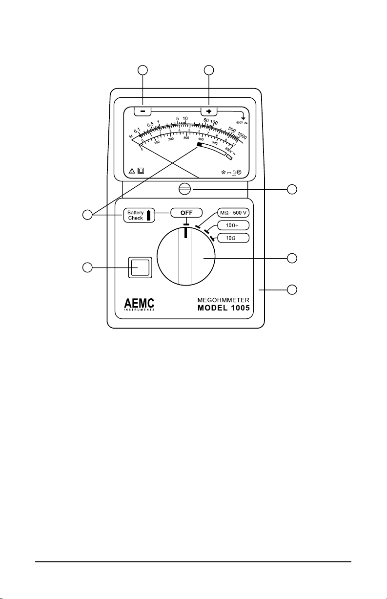
2.3 Model1005ControlFeatures ...................................................5
2.4 Model1015ControlFeatures ...................................................6
3. SPECIFICATIONS............................................................................. 7
3.1 ElectricalSpecications ............................................................7
3.2 GeneralSpecications..............................................................8
3.3 SafetySpecications ................................................................8
4. OPERATION .................................................................................... 9
4.1 SafetyCheck(VoltageTest) .....................................................9
4.2 InsulationResistanceTesting(MΩRange) ..............................9
4.2.1 TestVoltage ..................................................................9
4.2.2 SpotTesting ................................................................10
4.2.3 RatioTesting ...............................................................10
4.2.4
TipsForSuccessfulInsulationResistanceTesting ......... 11
4.2.5 InsulationMeasurement-Connections ...................... 11
4.2.6 InsulationResistanceMeasurementsonMotors........14
4.3 Continuity Measurements .......................................................15
4.4 ResistanceMeasurements(Model1015Only)......................15
5. MAINTENANCE ............................................................................. 16
5.1 Maintenance ...........................................................................16
5.1.1 Battery Test .................................................................16
5.1.2 BatteryandFuseReplacement ..................................17
5.1.3 Cleaning......................................................................17
RepairandCalibration...........................................................................18
TechnicalandSalesAssistance ............................................................18
Limited Warranty ...................................................................................19
WarrantyRepairs...................................................................................19
www.GlobalTestSupply.com
Quality AEMC Products Online at: sales@GlobalTestSupply.com

2
Megohmmeter Models 1005 and 1015
CHAPTER 1
INTRODUCTION
WARNING
Thesesafetywarningsareprovidedtoensurethesafetyofpersonnel
andproperoperationoftheinstrument.
• Readthisinstructionmanualcompletelyandfollowallthesafetyinfor-
mationbeforeattemptingtouseorservicethisinstrument.
• Safetyistheresponsibilityoftheoperator!
• Testsaretobecarriedoutonlyondeadcircuits!Checkforlivecircuits
beforemakingresistancemeasurements(safetycheck).
• Alwaysmakeconnectionsfromtheinstrumenttothecircuitundertest.
• Thesemegohmmetersare sourcesofhighvoltage,asisthesample
connectedtothem.Allpersonsperformingorassistinginthetestsmust
followallsafetyprecautionstopreventelectricalshocktothemselves
andtoothers.
• AEMC considers the use of rubber gloves to be an excellent safety
practice even if the equipment is properly operated and correctly
grounded.
• When testing capacitance samples, make sure that they have been
properlydischargedandthattheyaresafetotouch.Dielectricinsula-
tionsamplesshouldbeshort-circuitedforatleastvetimestheamount
oftimetheywereenergized.
• Neveropenthebackoftheinstrumentwhileconnectedtoanycircuitor
input.
1.1 International Electrical Symbols
This symbol signifies that the instrument is protected by double or rein-
forced insulation.
This symbol on the instrument indicates a WARNING and that the operator
must refer to the user manual for instructions before operating the
instrument. In this manual, the symbol preceding instructions indicates that
if the instructions are not followed, bodily injury, installation/sample and
product damage may result.
Risk of electric shock. The voltage at the parts marked with this symbol may
be dangerous.
In conformity with WEEE 2002/96/EC
www.GlobalTestSupply.com
Quality AEMC Products Online at: sales@GlobalTestSupply.com

Megohmmeter Models 1005 and 1015
3
1.2 Definition of Measurement Categories
Cat. I: Formeasurements on circuits not directly connected to theAC
supply wall outlet such as protected secondaries, signal level,
andlimitedenergycircuits.
Cat. II: For measurements performed on circuits directly connected to
the electrical distribution system. Examples are measurements
onhouseholdappliancesorportabletools.
Cat. III: For measurements performed in the building installation at
the distribution level such as on hardwired equipment in xed
installationandcircuitbreakers.
Cat. IV: For measurements performed at the primary electrical supply
(<1000V) such as on primary overcurrent protection devices,
ripplecontrolunits,ormeters.
1.3 Receiving Your Shipment
Uponreceiving your shipment, makesure that the contentsareconsis-
tentwith the packing list.Notify your distributor ofany missing items. If
theequipmentappearstobedamaged,leaclaimimmediatelywiththe
carrierandnotifyyourdistributoratonce,givingadetaileddescriptionof
anydamage.Savethedamagedpackingcontainertosubstantiateyour
claim.
1.4 Ordering Information
MegohmmeterModel1005..................................................Cat. #1402.01
MegohmmeterModel1015..................................................Cat. #1403.01
Both include a carrying case, shockproof rubber housing, set of black and red leads, black
test probe, red alligator clip, spare fuse (inside megohmmeter), 4 x 1.5V alkaline “AA” bat-
teries (not installed), and a user manual.
1.4.1 Accessories and Replacement Parts
Setofreplacementleads..................................................... Cat. #2118.41
CarryingCase...................................................................... Cat. #2118.40
Fuses,setof5,1.6A............................................................Cat. #2970.22
Order Accessories and Replacement Parts Directly Online
Check our Storefront at www.aemc.com for availability
www.GlobalTestSupply.com
Quality AEMC Products Online at: sales@GlobalTestSupply.com

4
Megohmmeter Models 1005 and 1015
CHAPTER 2
PRODUCT FEATURES
2.1 Description
TheMegohmmeters,Model1005and1015,areanaloginstrumentswith
foureasy-to-readscales.
TheMΩscaleisaneasy-to-readlogscalegraduatedfrom0.1to1000MΩ
(yellow background) at 500V and 1000V (Model 1015). The Ωscale is
linearwitharangefrom0to10Ω(whitebackground).
Tousethe0to1000ΩscaleontheModel1015,takethereadingonthe
0 to 10Ωrangeandmultiplythereadingby100.TheACvoltagescaleis
linearwitharangeof0to600VAC(whitebackground).Continuitytestsare
donewithatestcurrentof200mA.
Thecoloredbatteryscalehasarangeofgreenforagoodbatteryanda
rangeofredorlowerforadefectivebattery.
A built-in battery tester is provided by simply pressing the yellow push
buttonwhentheselectorswitchisintheOFFposition.
Voltmeter(safetycheck)witharangeof0to600VACisstandardandworks
when the selector switch is in the 500V position or the 1000V position
(Model1015only).
2.2 Features
• Measuresinsulationat500V(Model1005)
• Pushbuttonforbatterycheck
• Designed for harsh environments: offshore, mining, heavy-duty
eld,industrial,commercialelectricalandmilitaryuse
• 0to10Ω+ and 0 to 10Ω-continuityranges
• Continuity200mAtestcurrent
• Smallandlightweight
• Large,direct-reading,coloredscale
• 600Vtestvoltagerange(safetycheck)
• Yellownon-slipshockproofcase
• Measuresinsulationat1000V(Model1015Only)
• 0to1000Ωresistancerange(Model1015Only)
www.GlobalTestSupply.com
Quality AEMC Products Online at: sales@GlobalTestSupply.com

Megohmmeter Models 1005 and 1015
5
2.3 Model 1005 Control Features
–
1 2
3
4
5
6
7
Figure 1
1. Line(–)terminal
2. Earth/Ground(+)terminal
3. Mechanicalzeroadjustmentscrews
4. 4-positionrotaryswitch
5. Protectiverubberhousing
6. Push-to-testbutton
7. Batterycheckandindicationdisplay
www.GlobalTestSupply.com
Quality AEMC Products Online at: sales@GlobalTestSupply.com

6
Megohmmeter Models 1005 and 1015
2.4 Model 1015 Control Features
–
1 2
3
4
5
6
7
Figure 2
1. Line(–)terminal
2. Earth/Ground(+)terminal
3. Mechanicalzeroadjustmentscrews
4. 4-positionrotaryswitch
5. Protectiverubberhousing
6. Push-to-testbutton
7. Batterycheckandindicationdisplay
www.GlobalTestSupply.com
Quality AEMC Products Online at: sales@GlobalTestSupply.com

Megohmmeter Models 1005 and 1015
7
CHAPTER 3
SPECIFICATIONS
3.1 Electrical Specifications
INSULATION TESTS
DC Test Voltage:500V(Model1005)
500Vand1000 V(Model1015)
Megohm Range: 0.1 to 1000MΩ
Short Circuit Current: ≤6mA
Accuracy: ±5%ofreading
Discharging Time (Auto): 1s/µF
CONTINUITY TESTS
Range: 0 to 10Ω- ;0to10Ω+
Short Circuit Current: ≥200mA
Open Circuit Voltage: 4.5to6.5V
Accuracy: ±3%fullscale
RESISTANCE TESTS (Model 1015 Only)
Range: 0 to 1000Ω
Short Circuit Current: ≥2mA
Open Circuit Voltage: 4.5to6.5V
Accuracy: ±3%fullscale
VOLTAGE TESTS (Safety Check)
Voltage Range: 0to600VAC
Frequency: 45to400Hz
Accuracy:3%offullscale
Input Impedance:300kΩ
www.GlobalTestSupply.com
Quality AEMC Products Online at: sales@GlobalTestSupply.com

8
Megohmmeter Models 1005 and 1015
3.2 General Specifications
Power Supply: 4 x 1.5VAAbatteries
Dielectric Test:6000V,50/60 Hz,1minute
Meter Movement: Ruggedtautbandsuspension
Dimensions: 6.6x4.2x2.2"(167x106x55mm)
Weight:1.45lbs(650 g)
Operating Temperature Range:
14°to131°F(-10°to55°C),20-80%RH
Storage Range:-40°to158°F(-40°to70°C),10-90%RH
Terminals: “-”Line(black);“+”earth(red);accepts4mmbananaplugs
Reference Conditions: 63° to 73°F (17° to 23°C), 45-55% RH; Supply Voltage: 5.3 to 5.7V;
Voltage Frequency: 45 to 65Hz; Electric Field: <1V/M; Magnetic Field: <40A/M; Position:
Horizontal ± 5°.
3.3 Safety Specifications
IEC 1010-1: Safety requirements for electrical equipment for measure-
ment,controlandlaboratoryuse
VDE 0413-1:Insulationtesters
VDE 0413-4: Ohmmeters
VDE 0100:Specicationsforthecreationofhighcurrentinstallationsof
nominalvoltagelessthan1000V
IEC 801: Electromagnetic compatibility for measurement and control
equipmentinindustrialprocesses
Part2:Sectionsrelatingtoelectrostaticdischarges
Part3:Sectionsrelatingtoradiatedelectricelds
Part4:Sectionsrelatingtoelectrostaticdischarges
Part5:Sectionsrelatingtoelectricshocks
IEC 68.2.6: Vibrations
IEC 68.2.27:Shocks
IEC 68.2.29:Shakes
IEC 68.2.31:Bumps
IEC 68.2.32:Freefall
UL 94: Self-extinguishingcapability
Specications are subject to change at any time without notice
www.GlobalTestSupply.com
Quality AEMC Products Online at: sales@GlobalTestSupply.com

Megohmmeter Models 1005 and 1015
9
CHAPTER 4
OPERATION
4.1 Safety Check (Voltage Test)
WARNING: MAKE SURE THE JACKSARE FIRMLY INSERTED
INTOTHETOPOFTHEMEGOHMMETERPRIORTOPERFORM-
INGANYELECTRICALTESTS!
Before measuring insulation resistance, conrm that the sample is fully
discharged(particularlyindielectricandcapacitancesamples),andthat
thesampleisnotconnectedtoanenergizedcircuit.
To perform the voltage test:
• SettherangeselectiontoMΩ500VorMΩ1000V(Model1015only)
• Connectandreadonthevoltagescale(600VACmax)
Youdonotneedtopresstheyellowbuttontomeasurevoltage.
NOTE: IfmeasuringvoltageonaDCcircuit,thepointerwilldeect
butthemeasurementmaybeinaccurate.
4.2 Insulation Resistance Testing (MΩRange)
After checking for a live circuit (see Safety Check above), connect the
megohmmeter.
SeveralconnectionexamplesareillustratedinFigures3through10.
4.2.1 Test Voltage
Nopublishedstandardtellswhichvoltagetochooseforanygivenwinding.
However,publishedrecommendationscouldbesummarizedasfollows:
Rated Voltage of Motor Test Voltage
Below115 250V
115 250Vor500V
230 500V
460 500Vor1000V
www.GlobalTestSupply.com
Quality AEMC Products Online at: sales@GlobalTestSupply.com

10
Megohmmeter Models 1005 and 1015
4.2.2 Spot Testing
Asageneralruleinspottesting,testvoltageshouldbeapplieduntilno
variation in reading is noted for 15 seconds, or applied for a xed 60
seconds.
What minimum value should be measured?
TheIEEEstandardNo.43-1974statesthatitisimpossibletospecifythe
valueofinsulationresistanceatwhichawindingwillfailelectrically,buton
motors,minimumreadingsgenerallystatedare:
Rated Voltage R Minimum
250 or less 2MΩ
460 2MΩ
Thereisnoxedgurefordeterminingwhatisgoodandbadinresistance
readings,but a goodguidewouldbe1megohmfor every onehundred
appliedoperatingvolts,asaminimumgure.Thisappliestomotorsand
transformers. When the insulation resistance gets this low, an electri-
calbreakdowncanbeexpectedatanytime,andrewindingorreplacing
shouldbeconsidered.
Itisnotunusualfora winding to be 10 to 100 timestherecommended
minimumvalue(IEEEStd.#43-1974:Recommended Practice for Testing
Insulation Resistance of Rotating Machinery), but this varies with tem-
peratureandhumidity.
4.2.3 Ratio Testing
Intimeresistancereading(DielectricAbsorptionRatio),readingsaretaken
at30and60secondstoobtainthedielectricabsorptionratio.
Insulationresistance@60s=DielectricAbsorptionRatio(DAR)
Insulationresistance@30s
Thistestisusefultoincreasetheaccuracyofspottesting.Ingeneral,a
ratioof1.25:2orbettershouldberequired.Aratiobelowthisindicatesthat
repairisprobablyneeded.
Remember,aDCinsulationtestmaybeusedforacceptancetesting,but
ismorecommonlyusedtocheckthegradualdeteriorationofequipment
overitslife.Consultyourequipmentmanufacturerforspecictestortest
voltageifnotknown.
Insulationresistancedecreaseswithmoisture,temperatureandageand
shouldberecordedovertimeatagiventemperatureandcorrected.
www.GlobalTestSupply.com
Quality AEMC Products Online at: sales@GlobalTestSupply.com

Megohmmeter Models 1005 and 1015
11
4.2.4
Tips For Successful Insulation Resistance Testing
• Check with the equipment manufacturer for factory insulation
resistancereadings.
• Donotrelyoninsulationresistancetestingaloneasproofofwind-
ingconditions.
• Donotexpectthesamevalueforallpartsofallmachines.
• Observe consistent test time duration, recognizing that total
currentthroughinsulationundertestwillvarywithtime.
• Correctallreadingsproperlytoastandardreferencetemperature
(seeIEEEStd.#43-1974,TemperatureCorrectionCurve).
• Knowwhatyouaretesting.Isolatethepieceofequipmentfrom
othercircuitry.
• Watchtrendsratherthanrelyingonsingle“spot”readings.
4.2.5 Insulation Measurement - Connections
Figure3showstheconnectionstomeasuretheinsulationofoneconduc-
tor to the other conductors. The cable should be disconnected at both
endstoavoidleakagethroughswitchboardsandpanels.
OFF
MΩ- 1000 V
MΩ- 500 V
1000 Ω
AEMC
INSTRUMENTS
MEGOHMMETER
MODEL 1015
Battery
Check
10 Ω +
10 Ω −
0
.
1
0
.
5
1
5
1
0
5
0
1
0
0
5
0
0
1
0
0
0
0
1
2
3
4
5
6
7
8
9
1
0
0
1
0
0
2
0
0
3
0
0
4
0
0
5
0
0
6
0
0
V
600V
-
+
6
!
MΩ
Cable Insulation
Conductor Under Test
+
-
Figure 3
www.GlobalTestSupply.com
Quality AEMC Products Online at: sales@GlobalTestSupply.com

12
Megohmmeter Models 1005 and 1015
Figures4and5showtheconnectionsfortestinginsulationfromasupply
conductortoground(motorframe).
Cable Insulation
Conductor Under Test
+
-
OFF
MΩ- 1000 V
MΩ- 500 V
1000 Ω
AEMC
INSTRUMENTS
MEGOHMMETER
MODEL 1015
Battery
Check
10 Ω +
10 Ω −
0
.
1
0
.
5
1
5
1
0
5
0
1
0
0
5
0
0
1
0
0
0
0
1
2
3
4
5
6
7
8
9
1
0
0
1
0
0
2
0
0
3
0
0
4
0
0
5
0
0
6
0
0
V
600V
-
+
6
!
MΩ
Figure 4
Cable Insulation
Conductor Under Test
+
-
OFF
MΩ- 1000 V
MΩ- 500 V
1000 Ω
AEMC
INSTRUMENTS
MEGOHMMETER
MODEL 1015
Battery
Check
10 Ω +
10 Ω −
0
.
1
0
.
5
1
5
1
0
5
0
1
0
0
5
0
0
1
0
0
0
0
1
2
3
4
5
6
7
8
9
1
0
0
1
0
0
2
0
0
3
0
0
4
0
0
5
0
0
6
0
0
V
600V
-
+
6
!
MΩ
Figure 5
www.GlobalTestSupply.com
Quality AEMC Products Online at: sales@GlobalTestSupply.com

Megohmmeter Models 1005 and 1015
13
Figure6showstheconnectionsto
atransformer (lighting ordistribu-
tion).
Makesure that the switches and/
or circuit breakers on both sides
areopen.
Checkthehighvoltagewindingto
ground,lowvoltagetoground,and
theresistancebetweenthemwith
nowindinggrounded.
~
~
~~
~
~
Jumpers
+
-
OFF
MΩ- 1000 V
MΩ- 500 V
1000 Ω
AEMC
INSTRUMENTS
MEGOHMMETER
MODEL 1015
Battery
Check
10 Ω +
10 Ω −
0
.
1
0
.
5
1
5
1
0
5
0
1
0
0
5
0
0
1
0
0
0
0
1
2
3
4
5
6
7
8
9
1
0
0
1
0
0
2
0
0
3
0
0
4
0
0
5
0
0
6
0
0
V
600V
-
+
6
!
MΩ
Tested Winding
Transformer
Grounding Lug
-+
OFF
MΩ- 1000 V
MΩ- 500 V
1000 Ω
AEMC
INSTRUMENTS
MEGOHMMETER
MODEL 1015
Battery
Check
10 Ω +
10 Ω −
0
.
1
0
.
5
1
5
1
0
5
0
1
0
0
5
0
0
1
0
0
0
0
1
2
3
4
5
6
7
8
9
1
0
0
1
0
0
2
0
0
3
0
0
4
0
0
5
0
0
6
0
0
V
600V
-
+
6
!
MΩ
Figure 7 shows the connections for
measuring the insulation of a three-
phase line to ground by connecting
thejumpersbetweenphases.
Thisgivesareadingofallconductors
at once. If a load such as a motor,
heater, etc., is attached to the other
end of the line, it will read the load
resistance to ground at the same
time.
By removing the jumpers, readings
canbemade between the individual
conductorsandground.
Figure 6
Figure 7
www.GlobalTestSupply.com
Quality AEMC Products Online at: sales@GlobalTestSupply.com

14
Megohmmeter Models 1005 and 1015
4.2.6 Insulation Resistance Measurements on Motors
Figure8showsreadingtheresistancetogroundofathree-phasemotor
winding.Sincethethree-phasemotorsareinternallyconnected,itisonly
necessarytoconnectoneleadtothemotorleadandtheotherleadtothe
motorframeasshown.
+
-
OFF
MΩ- 1000 V
MΩ- 500 V
1000 Ω
AEMC
INSTRUMENTS
MEGOHMMETER
MODEL 1015
Battery
Check
10 Ω +
10 Ω −
0
.
1
0
.
5
1
5
1
0
5
0
1
0
0
5
0
0
1
0
0
0
0
1
2
3
4
5
6
7
8
9
1
0
0
1
0
0
2
0
0
3
0
0
4
0
0
5
0
0
6
0
0
V
600V
-
+
6
!
MΩ
Figure 8
Figure9showsthewind-
ings of a three-phase
motorseparated.
Sometimes this can be
done at the lead termi-
nals, while other times
the end bells must be
removed to get at the
leadwiresofthecoils.
By connecting the meg-
ohmmeterasshown,the
phase insulation resis-
tancevaluecannowbe
determined.
Read between phases “A”
and “B”, then “B” and “C”,
then“C”and“A”.
OFF
MΩ- 1000 V
MΩ- 500 V
1000 Ω
AEMC
INSTRUMENTS
MEGOHMMETER
MODEL 1015
Battery
Check
10 Ω +
10 Ω −
0
.
1
0
.
5
1
5
1
0
5
0
1
0
0
5
0
0
1
0
0
0
0
1
2
3
4
5
6
7
8
9
1
0
0
1
0
0
2
0
0
3
0
0
4
0
0
5
0
0
6
0
0
V
600V
-
+
6
!
MΩ
A
B
C
+
-
Figure 9
www.GlobalTestSupply.com
Quality AEMC Products Online at: sales@GlobalTestSupply.com

Megohmmeter Models 1005 and 1015
15
Figure 10 shows connec-
tions for testing insulation
fromasupplyconductorina
switchbox to ground (motor
frame).Anidenticaltestmay
becarriedoutfromthemotor
starter.
4.3 Continuity
Measurements
Onceithasbeenveriedthat
no voltage is present, the
continuitycheckmaybeper-
formed.
• Settheswitchtothe10Ω+
position. The measure-
ment is done automati-
cally;you do not need to
press the yellow button.
• Read the value on the
whitescale0to10Ω.
• Settheswitchtothe10Ω–positionandmakesurethattheneedleof
theinstrumentreadsthesamevalue.Ifthesecondvalueisdifferent
fromtheprecedingone,addupthetworeadingsanddividebytwo.
Thereasonfortakingtwodifferentreadingsistocomplywiththeinter-
nationalstandard VDE 0413-4. If your work does not require you to
conformtothisstandard,onlyonemeasurementisnecessary.
• Returnto“OFF”afteruse.
NOTE: For better measurement accuracy on the 10Ω+ and the
10Ω–ranges,measuretheresistanceoftheleadsbyshort-circuit-
ingthem,thensubtractthisvaluefromthemeasuredvalues.
4.4 Resistance Measurements (Model 1015 Only)
• Settheswitchtothe1000Ωposition.Themeasurementisdoneauto-
matically;you do not need to press the yellow button.
• Readthevalueonthewhitescale0to10Ω,thenmultiplythereading
by100togettheactualvaluemeasured.
• Returnto“OFF”afteruse.
Motor Side
of Switch:
Connection
to One Leg
Grounded
Motor Frame
Starter In
+
-
OFF
MΩ- 1000 V
MΩ- 500 V
1000 Ω
AEMC
INSTRUMENTS
MEGOHMMETER
MODEL 1015
Battery
Check
10 Ω +
10 Ω −
0
.
1
0
.
5
1
5
1
0
5
0
1
0
0
5
0
0
1
0
0
0
0
1
2
3
4
5
6
7
8
9
1
0
0
1
0
0
2
0
0
3
0
0
4
0
0
5
0
0
6
0
0
V
600V
-
+
6
!
MΩ
Figure 10
www.GlobalTestSupply.com
Quality AEMC Products Online at: sales@GlobalTestSupply.com

16
Megohmmeter Models 1005 and 1015
CHAPTER 5
MAINTENANCE
5.1 Maintenance
WARNING:
• Formaintenanceuseonlyspeciedreplacementparts.
• To avoid electrical shock, do not attempt to perform any servicing
unlessyouarequaliedtodoso.
• Toavoidelectricalshockand/ordamagetotheinstrument,donotget
waterorotherforeignagentsintothecase.TurntheinstrumentOFF
anddisconnecttheunitfromallthecircuitsbeforeopeningthecase.
5.1.1 Battery Test
Checkthatthebatteriesareingoodworkingconditionpriortousingthe
instrument.
With the switch in the OFF position, press the yellow button:
• Thebatteriesaregoodiftheneedleisinthegreenzone.
• The batteries need replacement if the needle is in the red zone or
lower.
The average battery life is:
• 1000insulationmeasurements
of10secondsontheMΩ-500V
rangeforR=500kΩ.
• 200 insulation measurements
of 10 seconds on the MΩ-
1000VrangeforR=1MΩ.
• 1500continuitymeasurements
of 10 seconds on the 10Ω
range.
NOTE: Theinstrumentwilloperatecorrectlywithabatteryvoltage
rangeof4.5to6.5V.
0
.
1
0
.
5
1
5
1
0
5
0
1
0
0
5
0
0
1
0
0
0
0
1
2
3
4
5
6
7
8
9
1
0
0
1
0
0
2
0
0
3
0
0
4
0
0
5
0
0
6
0
0
V
600V
-
+
6
!
MΩ
RED zone or below:
Battery needs to be replaced
GREEN zone:
Battery is good
www.GlobalTestSupply.com
Quality AEMC Products Online at: sales@GlobalTestSupply.com

Megohmmeter Models 1005 and 1015
17
5.1.2 Battery and Fuse Replacement
WARNING: Make sure that no terminals are connected and that the
switchisintheOFFpositionbeforeopeningthebackoftheinstrument.
• Removetheyellowshockproofhousing.
• Removethetwoscrewsfromthebackoftheinstrument(Fig.11).
• Removethebackcover.
• Replacethefuseorbatteries.
NOTE: Thereisasparefuseinstalledinthebackcover.
• Reversetheaboveproceduretoinstallthebackcoverandtheshock
proofhousing.
• Toclosethebackstandushwiththebackcover,applylightpressure
atPointAinFig.11.
+
+
+
+
Cover screws
1.5 V batteries LR6
1.6 A fuse
Point A
Figure 11
5.1.3 Cleaning
• Clean the body of the instrument with a cloth lightly moistened with
soapywater.
• Wipecleanwithaclothmoistenedwithcleanwateranddry.
• Donotusesolvent.
www.GlobalTestSupply.com
Quality AEMC Products Online at: sales@GlobalTestSupply.com

18
Megohmmeter Models 1005 and 1015
Repair and Calibration
Toensurethatyourinstrumentmeetsfactoryspecications,werecommend
thatitbescheduledbacktoourfactoryServiceCenteratone-yearintervals
forrecalibration,orasrequiredbyotherstandardsorinternalprocedures.
For instrument repair and calibration:
You must contact our Service Center for a Customer ServiceAuthorization
Number(CSA#).Thiswillensurethatwhenyourinstrumentarrives,itwillbe
trackedandprocessedpromptly.PleasewritetheCSA#ontheoutsideofthe
shipping container. If the instrument is returned for calibration, we need to
knowifyouwantastandardcalibration,oracalibrationtraceabletoN.I.S.T.
(Includescalibrationcerticateplusrecordedcalibrationdata).
Ship To: ChauvinArnoux®,Inc.d.b.a.AEMC®Instruments
15 Faraday Drive
Dover,NH03820USA
Phone:(800)945-2362(Ext.360)
(603)749-6434(Ext.360)
Fax: (603)742-2346or(603)749-6309
E-mail:[email protected]
(Orcontactyourauthorizeddistributor)
Costsforrepair,standardcalibration,andcalibrationtraceabletoN.I.S.T.are
available.
NOTE: You must obtain a CSA# before returning any instrument.
Technical and Sales Assistance
Ifyouareexperiencinganytechnicalproblems,orrequireanyassistancewith
theproperoperationorapplicationofyourinstrument,pleasecall,mail,faxor
e-mailourtechnicalsupportteam:
ChauvinArnoux®,Inc.d.b.a.AEMC®Instruments
200FoxboroughBoulevard
Foxborough,MA02035USA
Phone:(800)343-1391
(508)698-2115
Fax: (508)698-2118
E-mail:[email protected]
www.aemc.com
NOTE: Do not ship Instruments to our Foxborough, MA address.
www.GlobalTestSupply.com
Quality AEMC Products Online at: sales@GlobalTestSupply.com
This manual suits for next models
1
Table of contents