AEMC AX501 User manual

DC POWER SUPPLY AX501
AX502
AX503
E N G L I S H User Manual
IEC 61010-1
POWER
ON
OFF
AX 501
8.8.8.
VOLTAGE
8.8.8.
CURRENT
100V
CAT I
V A
30V LIMIT
0
COARSEFINE
2.5A
0
IEC 61010-1
POWER
ON
OFF
AX 503
8.8.8. 8.8.8. 8.8.8. 8.8.8.
MASTER
TRACKING
SLAVE
100V
CAT I
100V
CAT I
100V
CAT I
A V A VV
2.5A
30V
3V
5V
2.7V 5.5V
LIMIT 5ALIMIT LIMIT
ON
0
0
COARSEFINE FINE
2.5A
30V
0
0
COARSE
www.GlobalTestSupply.com
Find Quality Products Online at: sales@GlobalTestSupply.com

Statement of Compliance
Chauvin Arnoux®, Inc. d.b.a. AEMC®Instruments
certifies that this instrument has been calibrated
using standards and instruments traceable to
international standards.
We guarantee that at the time of shipping your
instrument has met its published specifications.
An NIST traceable certificate may be
requested at the time of purchase, or obtained
by returning the instrument to our repair and
calibration facility, for a nominal charge.
The recommended calibration interval for this
instrument is 12 months and begins on the date of
receipt by the customer. For recalibration, please
use our calibration services. Refer to our repair
and calibration section at www.aemc.com.
Serial #: ________________________________
Catalog #: 2130.05 / 2130.06 / 2130.07
Model #: AX501 / AX502 / AX503
Please fill in the appropriate date as indicated:
Date Received: _________________________________
Date Calibration Due: _______________________
Chauvin Arnoux®, Inc.
d.b.a AEMC®Instruments
www.aemc.com
www.GlobalTestSupply.com
Find Quality Products Online at: sales@GlobalTestSupply.com

Table of Contents
1. INTRODUCTION............................................................................... 3
1.1 International Electrical Symbols................................................3
1.2DenitionofMeasurementCategories .....................................4
1.3ReceivingYourShipment..........................................................4
1.4OrderingInformation.................................................................4
1.4.1 Accessories ..................................................................4
2. PRODUCT FEATURES ...................................................................... 5
2.1Description................................................................................5
2.2ControlFeatures .......................................................................6
2.2.1ModelAX501 ................................................................6
2.2.2ModelAX502 ................................................................7
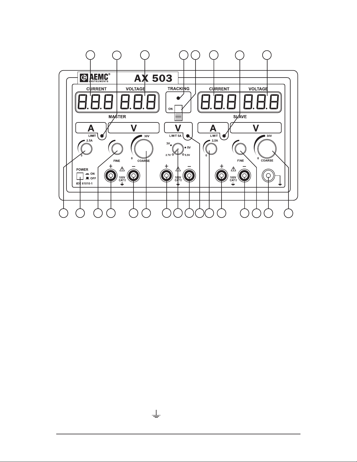
2.2.3ModelAX503 ................................................................8
2.3ControlDescriptions .................................................................9
2.3.1PowerOn/OButton.....................................................9
2.3.2VoltageandCurrentAdjustments .................................9
2.3.3Current“LIMIT”LED .....................................................9
2.3.4“TRACKING”Switch(ModelsAX502andAX503).........10
2.3.5Setting“TRACKING”...................................................10
2.3.6Digital“LED”displays ................................................. 11
2.3.7OutputTerminals.........................................................11
2.3.8GroundTerminal .........................................................11
2.4PowerSupply..........................................................................11
3. SPECIFICATIONS........................................................................... 12
3.1 SpecicationChart..................................................................12
3.2GeneralSpecications............................................................13
3.3SafetySpecications ..............................................................14
4. OPERATION .................................................................................. 15
4.1BeforeUsingtheInstrument...................................................15
4.2OperatingInstructions.............................................................15
4.2.1UsingIndependentOutputs ........................................16
4.2.2Useof2OutputsinParallel(AX502andAX503) .......16
www.GlobalTestSupply.com
Find Quality Products Online at: sales@GlobalTestSupply.com

4.2.3Useof2OutputsinSeries(AX502andAX503) .........17
4.2.4Useof2.7Vto5.5V(5A)PowerSupply(AX503Only) ...18
5. MAINTENANCE ............................................................................. 19
5.1Warning...................................................................................19
5.2FuseReplacement..................................................................19
5.3Cleaning..................................................................................19
5.4Storage ...................................................................................19
RepairandCalibration...........................................................................20
TechnicalandSalesAssistance ............................................................20
Limited Warranty ...................................................................................21
WarrantyRepairs...................................................................................21
www.GlobalTestSupply.com
Find Quality Products Online at: sales@GlobalTestSupply.com

DC Power Supply Models AX501, AX502 and AX503
3
CHAPTER 1
INTRODUCTION
WARNING
Thesesafetywarningsareprovidedtoensurethesafetyofpersonnel
andproperoperationoftheinstrument.
• Readthisusermanualcompletelyandfollowallthesafetyinformation
beforeattemptingtouseorservicethisinstrument.
• Usecautiononanycircuit:Potentiallyhighvoltagesandcurrents
maybepresentandmayposeashockhazard.
• Onlyuseleadswiththeproperrating.Alwaysinspecttheinstrument
andleadpriortouse.Replaceanydefectivepartsimmediately.
• Safetyistheresponsibilityoftheoperator!
• Anydefectiveleadinsulation,insideoroutsideoftheinstrument,or
disconnectionoftheprotectiveearth/groundterminalmaymakethe
instrumentdangerous.
• Theplugshouldonlybeinsertedintoasocketequippedwitha
groundingcontact.Thesafetyconnectionmustnotbebrokenby
useofanextensionleadwithoutprotectiveinsulation.
• Beforeconnectingthepowersupply,makesurethedistributionnet-
workis115VAC±10%.
1.1 International Electrical Symbols
Thissymbolsigniesthattheinstrumentisprotectedbydoubleor
reinforcedinsulation.Useonlyspeciedreplacementpartswhen
servicingtheinstrument.
ThissymbolontheinstrumentindicatesaWARNINGandthat
theoperatormustrefertotheusermanualforinstructionsbefore
operatingtheinstrument.Inthismanual,thesymbolpreceding
instructionsindicatesthatiftheinstructionsarenotfollowed,
bodilyinjury,installation/sampleandproductdamagemayresult.
Riskofelectricshock.Thevoltageatthepartsmarkedwiththis
symbolmaybedangerous.
Earth/Ground
www.GlobalTestSupply.com
Find Quality Products Online at: sales@GlobalTestSupply.com

4
DC Power Supply Models AX501, AX502 and AX503
1.2 Definition of Measurement Categories
CAT II: Formeasurementsperformedoncircuitsdirectlyconnectedto
theelectricaldistributionsystem.Examplesaremeasurements
onhouseholdappliancesorportabletools.
CAT III:Formeasurementsperformedinthebuildinginstallationat
thedistributionlevelsuchasonhardwiredequipmentin xed
installationandcircuitbreakers.
CAT IV: Formeasurementsperformedattheprimaryelectricalsupply
(<1000V)suchasonprimaryovercurrentprotectiondevices,
ripplecontrolunits,ormeters.
1.3 Receiving Your Shipment
Uponreceivingyourshipment,makesurethatthecontentsareconsistent
withthepackinglist.Notifyyourdistributorofanymissingitems.Iftheequip-
mentappearstobedamaged,leaclaimimmediatelywiththecarrierand
notifyyourdistributoratonce,givingadetaileddescriptionofanydamage.
Savethedamagedpackingcontainertosubstantiateyourclaim.
1.4 Ordering Information
DCPowerSupplyModelAX501..........................................Cat. #2130.05
(Single output, 0 to 2.5A; 0 to 30VDC)
DCPowerSupplyModelAX502..........................................Cat. #2130.06
(Dual output, 0 to 2.5A; 0 to 30VDC; 110V, 60Hz, US plug)
DCPowerSupplyModelAX503..........................................Cat. #2130.07
(Triple output, two 0 to 2.5A; 0 to 30VDC; 5A; 2.7 to 5.5VDC;
110V, 60Hz, US plug)
1.4.1 Accessories
LeadSet(2color-codedleads,1groundlead,
2alligatorclipsand2gripprobes)....................................... Cat. #2117.78
Setof5Fuses10A/250V,5x20mmSlowBlow ................... Cat. #2118.83
Order Accessories and Replacement Parts Directly Online
Check our Storefront at www.aemc.com/store for availability
www.GlobalTestSupply.com
Find Quality Products Online at: sales@GlobalTestSupply.com

DC Power Supply Models AX501, AX502 and AX503
5
CHAPTER 2
PRODUCT FEATURES
2.1 Description
Thiscomprehensiverangeoflinearpowersupplieswithdigitaldisplays
isdesignedtomeettherequirementsofeducationalestablishments,
laboratories,productiontestsandmaintenancedepartments.
Itoersahighlevelofoperatingsafetybyguaranteedinsulationofthe
outputsfromthemainswhenusedatanextralowsafetyvoltage,a
comprehensiveprotectionsystemand excellentergonomics.
Thequalityofthesignaldelivered,theprecisionofthedisplayandthe
robustnessofthehousingmakethemtop-levellaboratoryinstruments.
The AX501 oers:
•Singleoutput
•Simultaneousdisplayoftheoutputvoltageandcurrent
•Voltageadjustablefrom0to30Vforavariablecurrentof
0to2.5A(75W)
The AX502 oers:
•Dualoutput
•Simultaneousdisplayoftheoutputvoltageandcurrentforeach
output
•Two0to30V,0to2.5A(150Wmax)outputs;connectedinseries,
parallelorcoupled,(trackingfunction)±30V
The AX503 oers:
•Triplepowersupply
•Simultaneousdisplayoftheoutputvoltageandcurrentforeach
0-30Voutput
•Two0to30V,0to2.5A(150Wmax)outputs;connectedinseries,
parallelorcoupled,(trackingfunction)±30V
•Anadjustable2.7to5.5V,5Axedoutputforsupplyinglogiccir-
cuitsat3Vor5V
www.GlobalTestSupply.com
Find Quality Products Online at: sales@GlobalTestSupply.com

6
DC Power Supply Models AX501, AX502 and AX503
2.2 Control Features
2.2.1 Model AX501
2
4
5
6
7
8
1
9
10
3
Figure 1
1.Voltagedisplay(green)
2.Currentdisplay(red)
3.CurrentlimitLED
4.PowerOn/Obutton
5.Finevoltageadjustmentpotentiometer
6.Outputterminal(+)
7.Outputterminal(-)
8.Coarsevoltageadjustmentpotentiometer
9.Currentlimitadjustmentpotentiometer
10.Groundterminal()
www.GlobalTestSupply.com
Find Quality Products Online at: sales@GlobalTestSupply.com

DC Power Supply Models AX501, AX502 and AX503
7
2.2.2 Model AX502
1
7
6
8
9
10
11
1
3
2
2
3
4
5
6
12
9
10
11
8
Figure 2
1.Currentdisplay(red)
2.CurrentlimitLED
3.Voltagedisplay(green)
4.TrackingfunctionLED
5.TrackingOn/Oswitch
6.Currentlimitadjustmentpotentiometer
7.PowerOn/Obutton
8.Finevoltageadjustmentpotentiometer
9.Outputterminals(+)
10.Outputterminals(-)
11.Coarsevoltageadjustmentpotentiometer
12.Groundterminal()
www.GlobalTestSupply.com
Find Quality Products Online at: sales@GlobalTestSupply.com

8
DC Power Supply Models AX501, AX502 and AX503
2.2.3 Model AX503
10
9
12
1
7
6
8
9
10 11
1
3
2
2 3
4 5
6
1413
9
10 11
8
Figure 3
1.Currentdisplay(red)
2.CurrentlimitLED
3.Voltagedisplay(green)
4.TrackingfunctionLED
5.TrackingOn/Oswitch
6.Currentlimitadjustmentpotentiometer
7.PowerOn/Obutton
8.Finevoltageadjustmentpotentiometer
9.Outputterminals(+)
10.Outputterminals(-)
11.Coarsevoltageadjustmentpotentiometer
12.Voltageadjustmentpotentiometer
13.5AcurrentlimitLED
14.Groundterminal()
www.GlobalTestSupply.com
Find Quality Products Online at: sales@GlobalTestSupply.com

DC Power Supply Models AX501, AX502 and AX503
9
2.3 Control Descriptions
2.3.1 Power On/Off Button
UsedtoturnthepowerONandOFF.
2.3.2 Voltage and Current Adjustments
• Voltage Adjustment:
-Setstheregulatedvoltageoutputbyturningthelargeknob
(COARSEadjustment)totheright(increasesoutput)orleft
(decreasesoutput).
-Setstheregulatedvoltageoutputbyturningthesmallknob
(FINEadjustment)totheright(increasesoutput)orleft
(decreasesoutput).TheFINEadjustmentrangerepresents
approximately10%ofthemainrange.
-Thevalueofthevoltageoutputisdisplayedinrealtimeonthe
greendisplay.
• Current Adjustment:
-Adjustthevalueofthecurrentlimitbyturningtheknobtothe
right(increasesoutput)orleft(decreasesoutput).
-Thecurrentvaluedisplayedisthevalueoftheoutputcurrent
onthereddisplay.
2.3.3 Current “LIMIT” LED
TheAXSeriesPowerSuppliesprovidestheabilitytolimitthecurrent
output.Whenthe“limit”isreached,thepowersupplywillswitchto“current”
regulationtoensurethecurrentoutputand dropsthevoltageregulation.
Setting a Current Limit:
•Shorttheoutputterminals,andadjustthecurrenttothedesired
limit(youmayneedtohavealittlevoltageforthecurrenttoow).
Thevalueofcurrentowwillbedisplayedontheappropriatedis-
play.
•Turnthevoltageoutputoandconnecttothesample.Asthevolt-
ageisincreased,ifthecurrentreachesthesetlimit,the“LIMIT”
LEDwillturnon,andthecurrentwillnolongerincrease.
•Thecurrentlimitmaybeoverriddensimplybyincreasingthecur-
rentoutputmanually.
www.GlobalTestSupply.com
Find Quality Products Online at: sales@GlobalTestSupply.com

10
DC Power Supply Models AX501, AX502 and AX503
2.3.4 “TRACKING” Switch (Models AX502 and AX503)
• “TRACKING” Mode
-Thiscontrolenablestwo“0to30V”sourcestobecontrolledin
series mode.
-Whenthe“TRACKING”buttonisswitchedtoON,itsetsupa
seriesconnectionbetweenthe“–”terminaloftheMASTER
powersupplyandthe“+”terminaloftheSLAVEpowersupply.
Theexternalterminalsareusedtoconnectthepointsinthe
circuittobepowered.
-OnlythevoltagesettingsoftheMASTERmodulecausethe
voltagesoftheMASTERandSLAVEtovaryproportionally.
• “TRACKING” LED
-WhenthisLEDison,the“TRACKING”functionhasbeenacti-
vated.
2.3.5 Setting “TRACKING”
TheSLAVEtracksasa%oftheMASTERoutput.Youneedtosetthis%
beforeturningontheTracking.
Toset-uptheTracking,rstsettheMASTERvoltageoutput,thensetthe
SLAVEoutput%.Tosetthis%,simplyadjusttheSLAVEoutputvoltage.
NOTE:ThinkoftheSLAVEdisplayasa%(10.0=100%,5.0=50%,
20.0=200%).OncetheSLAVE%isset,switchingtheTrackingON
willcausetheSLAVEtotracktheMASTERattheinputted%.
Example:
WewanttheSLAVEtoTracktheMASTER@30%oftheMASTERoutput
voltage,andwewanttoTrackstarting@10.0VoutoftheMASTER.
•MakesuretheTrackingisOFF
•SettheMASTERVoltageto10.0V
•SettheSLAVEto30%(3.0V)
•TurntheTrackingswitchtoON
•TheMASTERwilldisplay10.0VandtheSLAVEwilldisplay3.0V
•AstheMASTERisincreasedordecreased,theSLAVEwilltrack
@30%
•DuringTracking,theSLAVELEDdisplaystheactualSLAVE
outputvoltage
www.GlobalTestSupply.com
Find Quality Products Online at: sales@GlobalTestSupply.com

DC Power Supply Models AX501, AX502 and AX503
11
Intheprevioussetting, iftheMASTERisincreasedto20.0V,theSLAVE
willtrackanddisplay6.0V(30%of20.0V).
IfyouwanttheSLAVEtotracktheMASTER@100%,settheSLAVEto
10.0duringthesetup.
IfyouwanttheSLAVEtotracktheMASTER@200%,settheSLAVEto
20.0duringthesetup(theoutputthoughisstilllimitedto30.0V).
2.3.6 Digital “LED” displays
Aseparatedisplayallowsyoutoviewthevoltageoutput(ingreen)andthe
currentoutput(inred)simultaneouslyforeach30Voutput.
Thedisplaysare3-digitLEDindicatorswitharesolutionof0.1Vand
10mA.
2.3.7 Output Terminals
Thefemaletwo-pin“+”and“–”safetyterminals(Ø4mm)areusedto
connecttheoutputstothepointsofthecircuittobepoweredbymeansof
safetyleadsonly.
2.3.8 Ground Terminal
ThisterminalisdirectlylinkedinternallytothegroundontheACpower
plug.
Itenablesgroundingofthecircuittobepowered,ifnecessary.
Itsmalepolarityand“green/yellow”color-codingwillpreventanyconfusion
intheconnections.
Interruption of the protective ground conductor, inside or out-
side the power supply, is prohibited.
2.4 Power Supply
TheAXSeriesPowerSuppliesarefactoryconguredat115V±10%;
50/60Hz.Consultthefactoryforchangingto220Vsupply.
www.GlobalTestSupply.com
Find Quality Products Online at: sales@GlobalTestSupply.com

12
DC Power Supply Models AX501, AX502 and AX503
CHAPTER 3
SPECIFICATIONS
3.1 Specification Chart
Only the values assigned tolerances or the declared limits constitute guaranteed values.
Values without tolerances are given as indications and the measurement errors must be
considered in the reference temperature conditions, (e.g. 23° C ± 5° C).
4.1. Voltage
AX 501 AX 502 AX 503
Range available 0-30V
2x(0-30V)
or
1x(0-60V)
+TRACKING
2x(0-30V)
or
1x(0-60V)
+TRACKING
+output
2.7 V to 5.5 V
Adjustment coarseandne
bypotentiometers
by
potentiometer
Display greenLEDs none
Resolution 0.1V-
Accuracy ±0.5%ofreading±1digit -
Stability if variation:
mains ± 10%
of the 0 to 2.5 A load
of the 0 to 5 A load
±(0.03%R+2mV)
±(0.02%R5mV)
-
± 4 mV
-
±(0.2%R
+10mV)
Residual ripple in
load < 1 mVrms ± 1 mVrms
Common mode
voltage 60Vpeak
Protection against
short-circuit currentelectroniclimitation
Coupling of outputs -seriesorparallel -
"TRACKING"
(master/slave) - yes -
To avoid signicant drops in voltage during regulation verication measurements, the
contact resistances of the connections must be very low (≤1mΩ).
www.GlobalTestSupply.com
Find Quality Products Online at: sales@GlobalTestSupply.com

DC Power Supply Models AX501, AX502 and AX503
13
4.2. Current
AX 501 AX 502 AX 503
Range available 0-2.5A
2x(0-2.5A)
or
1x(0-5A)
2x(0-2.5A)
or
1x(0-5A)
+output5A
Adjustment bypotentiometer none
Display red LEDs -
Resolution 10mA -
Accuracy ±0.5%ofreading±1digit -
Output current
limitation adjustablefrom0to2.5Alimited to
5A±5%
Residual current < 22.5 mA
Indication of limitation LED
Short-circuit protection currentlimitation
Protection against
overheating yes
3.2 General Specifications
Power Supply:115VAC±10%Consultthefactoryforchangingto220VAC.
Display:Dualdisplay-“VOLTAGE”inGreenand“CURRENT”inRed;
7-segments;0.56"(14.2mm)digitsize.
Operating Temperature Range: 50°to104°F(10°to40°C)
Storage Temperature Range: -4°to158°F(-20°to+70°C)
Temperature Coecient: <0.1xaccuracy/°C
Operating Relative Humidity:<80%RHupto104°F(40°C)
Electrical Field: nil
Magnetic Field: <40A/m
Dimensions (without knobs):
10.63x8.86x4.73"(270x225x120mm)
Weight:AX501:8.8lbs(4kg)
AX502:9.9lbs(4.5kg)
AX503:13.2lbs(6kg)
www.GlobalTestSupply.com
Find Quality Products Online at: sales@GlobalTestSupply.com

14
DC Power Supply Models AX501, AX502 and AX503
3.3 Safety Specifications
IEC1010-1(NFEN61010-1+A2:1995)Class1;PollutionDegree2
Powersupplyoutputs:OvervoltageCat.100V,CATI
Max.OutputVoltage:30.5VDC in normal mode
61.0VDC in series mode
Powersupplyinputs:OvervoltageCAT300V,CATII
SupplyCurrent:115V±10%;50/60Hz
Electromagnetic Compatibility:
EN50081-11992;EN50082-21998
*Specications are subject to change without notice
www.GlobalTestSupply.com
Find Quality Products Online at: sales@GlobalTestSupply.com

DC Power Supply Models AX501, AX502 and AX503
15
CHAPTER 4
OPERATION
4.1 Before Using the Instrument
•Whentherequiredvoltageandcurrentparametervaluesarenot
known,startbyusingthelowestvalues.
•Beforedisconnectingtheleadsofthecircuitundertest,makesure
thatthepowersupplyisturnedo.Thispreventsthecreationof
breakorclosureextra-currentswhichmaymeltthefuseathigh
currents.
•Neverexceedatotaloutputof60Vpeakinrelationtothe
ground.
•Theinstrumentmustbeplacedinaventilatedroom.Donot
obstructtheventilationholes.
•Beforeopeningtheinstrument,disconnectitfromallsourcesof
electriccurrentandfromthemeasuringcircuits;makesurethat
youarenotchargedwithstaticelectricity,whichcouldirreparably
damagetheinstrument’sinternalcomponents.
WARNING: Whentheinstrumentisopen,someoftheinternal
capacitorsmaybedangerous,evenoncetheinstrumenthasbeen
powereddown.
Intheeventoffaultsorabnormalconstraints,turn the instrument
OFFanddonotuseituntilithasbeenchecked.
4.2 Operating Instructions
•Checkthelabelattherearofthepowersupplytomakesurethat
theinstrumentissettotheAClinevoltagecompatiblewithyour
setting.
•ConnecttheACpowercordtothesupply.
•Noconnectionsshouldbemadebefore poweringup.
•
StartupthepowersupplybypushingthePowerOn/ObuttonON.
•ToturnOFFtheinstrument,unplugtheleadsandpushthePower
On/ObuttonOFF.
www.GlobalTestSupply.com
Find Quality Products Online at: sales@GlobalTestSupply.com

16
DC Power Supply Models AX501, AX502 and AX503
4.2.1 Using Independent Outputs
•ConnecttheACpowercordtothesupply.
•Makesurethatthevoltageadjustmentcontrolsandcurrentadjust-
mentcontrolsareturnedtotheleftasfarastheywillgo(minimum
voltageandcurrent).
•Makesurethatthe“TRACKING”switchisintheOFFposition.
•Ifnecessary,connecttheEarth/Groundterminaltothegroundof
thecircuittobepowered(toprovide protection)andthePositive
andNegativeterminalstothepointsofthecircuittobepowered,
usingthetestcables.
•Checkthequalityandpolarityoftheconnectiontothesample.
•PressthePowerOn/ObuttonON.The“LIMIT”LEDshouldbe
OFF.
•Setthevoltagetoberegulated byturningthevoltagecontrols
totheright(increasingvalues).Thevoltagesetpointisthendis-
played.
•Adjustthevalueofthecurrentlimitbyturningthecurrentcontrol
totheright(increasingvalues).Thecurrentvaluedisplayedisthe
valueoftheoutputcurrent.Shorttheoutputwithaleadtoadjust
theoutputcurrent(See§2.3.3).
•Duringuse,whentheoutputcurrentreachesthelimitcurrent
value,thepowersupplyautomaticallyswitchesto“current”reg-
ulationmode,the“LIMIT”LEDturnsONandthevoltageisno
longerregulated.
4.2.2 Use of 2 Outputs in Parallel (AX502 and AX503)
To use 2 outputs in parallel (without “TRACKING”) up to 5A at 30V
max (see Fig. 4):
•Setthe“TRACKING”switchtotheOFFposition.
•Setthe2powersupplies(MASTERandSLAVE)tothesame
outputvoltagevalue.
•Linkthe“+”terminalstogetherandthe“–”terminalstogetherusing
shortleads.
•Connectoneofthetwo“+”terminalsandoneofthetwo“–”termi-
nalstothecircuittobepowered.
www.GlobalTestSupply.com
Find Quality Products Online at: sales@GlobalTestSupply.com

DC Power Supply Models AX501, AX502 and AX503
17
V max: 30V
Current max: 5.0A
ON
Sample
Figure 4
4.2.3 Use of 2 Outputs in Series (AX502 and AX503)
To use 2 outputs in series (without “TRACKING”) up to 60V at 2.5A
max (see Fig. 5):
•Setthe“TRACKING”switchtotheOFFposition.
•Setthe2powersupplies(MASTERandSLAVE)tothesamecurrent
limitationvalue.
•Usealeadtoshortthe“+”terminalofonepowersupplytothe“–”
terminaloftheotherpowersupply.Usethetwo“+”and“–”terminals
thatremainfreetomaketheconnectionwiththecircuittobepowered.
V max: 60V
Current max: 2.5A
ON
Sample
Figure 5
To use 2 outputs in series (with “TRACKING”), symmetrical ±30V
sources at 2.5A max (see Fig. 6):
Procedure:(forserialnumber>105500MAV)
•Insequence(powersupplyathenb),adjustthe "current"potentiometers
todeneidenticallimitcurrents.
•Setthe2Voltagepotentiometersoftheslavetothemaximum(around
30.5V).
•Pressthe"TRACKING"button("ON",LEDlit).Whensetto"ON",a
seriesconnectionbetweenthe"-"terminalofthe"MASTER"power
supplyandthe"+"terminalofthe"SLAVE"powersupplyisset.
•The"MASTER"sourceisontheleft(a);settherequiredinitialvoltage,
adjustittothedesiredvoltage.
•The"SLAVE"sourceisontheright(b).
www.GlobalTestSupply.com
Find Quality Products Online at: sales@GlobalTestSupply.com

18
DC Power Supply Models AX501, AX502 and AX503
•Inthisfunction,onlythevoltagecontrolsofthe"MASTER"source(a)
willbeusedfromnowon.
•Connectthecircuittobepowered(externalterminalsofthe"MASTER"
and"SLAVE"powersupplies).
•Thesymmetrical"SLAVE"source(b)reactstothe"MASTER"source
(a)voltagevariationsbyproportional"tracking"variationsinabsolute
values("TRACKING"function).
NOTE: Fortheuseofsymmetricalvoltages(e.g.±15V),oneofthe
2terminals(MASTER“–”orSLAVE“+”)willbeconnectedtothe
circuittobepowered(“0”point).
Proportional T
racking from 0 - 30V
Current max: 2.5A
ON
SampleN
Figure 6
NOTE:IftheSLAVEsourceistakenoutsideitsoperatinglimits
(voltageorcurrent)bytheMASTERsource,thecorresponding
“LIMIT”LEDlightsup.
4.2.4 Use of the 2.7V to 5.5V (5A) Power Supply (AX503 Only)
•Ifnecessary,connecttheearth/groundterminalto thecircuittobe
powered.
•Connectthe“+”and“–”terminalstothepointsofthecircuittobe
poweredusingtheconnectionleads.
•Settherequiredvoltagebetween2.7Vand5.5Vusingtheadjustment
control.
•For “FINE”adjustment,connecttheseterminalstoamultimeter
(appropriaterange).
•Iftheoutputcurrentreachesthe5Alimitcurrentvalue,the“LIMIT5A”
LEDcomeson,thepowersupplyautomaticallyswitchesto“current”
regulationmodeandthevoltageisnolongerregulated.
NOTE: Thisoutputisdesignedtopowerlogiccircuitsat3or5Vwith
consumptionupto5A.
www.GlobalTestSupply.com
Find Quality Products Online at: sales@GlobalTestSupply.com
Other manuals for AX501
2
This manual suits for next models
2
Table of contents
Other AEMC Power Supply manuals
Popular Power Supply manuals by other brands

nextys
nextys NPSM240 Series instruction manual

Nemic-Lambda
Nemic-Lambda ZUP Series manual

TechLogix Network
TechLogix Network TL-PKPS-01 user manual

TET Electronics
TET Electronics ARGOS-500 instruction manual

Altronix
Altronix AL300ULX installation guide

Rohde & Schwarz
Rohde & Schwarz NGP804 Getting started