aeolus UC-1901M User manual

Distributor Contacts
UC-1801
KO2-10FKO2-2F
UC-1901
Professional Multifunctional
Veterinary Intensive Care Unit
WMS-1501
Professional Vet Equipments Supplier
User Manual
01
Overview
CONTENTS
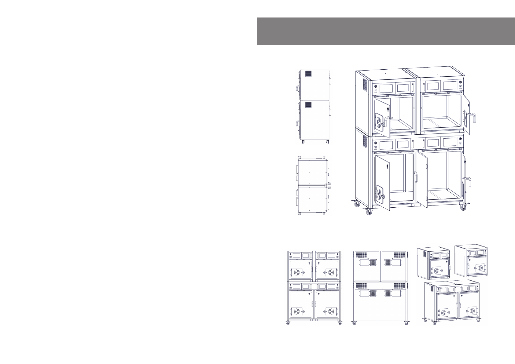
Side View
Top View
Front View Rear View Separated View
Overview …………………………………………..............................
Product dimensions …………………………………………….........
General usage guidelines ………………………………….…….......
General opreation tips ………………………………........................
Radio requency interferece ………………………………................
Choosing the working space for the unit ......................................
Parameters ……………………………………………......................
Operation guidance …………………………………………….........
Setting interface ……………………………………………..............
Setting mode ……………………………………………...................
Trouble shooting …………………………………………...................
Non-alarming components .....……………………………................
Maintenance and cleaning …………………………………….…....
01
02
03
03
03
04
05
06
07
08
14
17
18
02
Product Dimensions General Usage Guidelines
General Operation Tips
Radio Requency Interferece
03
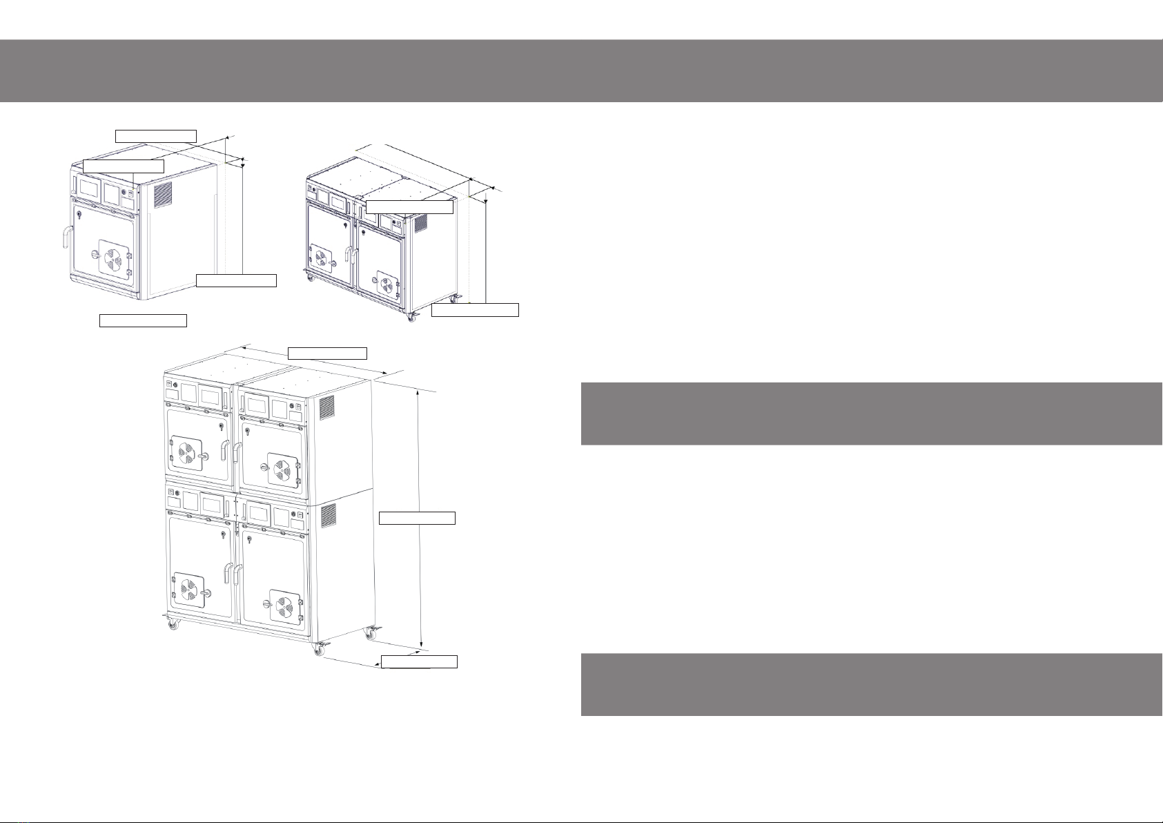
Internal dimension of large compartment: 1236×600×695mm (4 ft 21/32 inch × 1 ft 11 5/8 inch × 2
ft 3 23/64 inch)
Internal dimension of medium compartment: 550×600×485mm (1 ft 9 21/32 inch × 1 ft 11 5/8 inch
× 1 ft 7 3/32 inch)
The KaniStar UC-1901 Multifunctional Veterinary Intensive Care Unit is For Animal Use Only.
There is no reference in this handbook for human hospitals or home users.
Normothermia maintenance, fluid transfusion, oxygen supplement, blue light therapy, nebulization
treatment, emergency rescue, in house observation can all be carried out by this unit.
All normal operations and maintenance of the unit should be done by a qualified trained operator under
the supervision of a licensed qualified veterinarian.
The manufacturer will not be responsible or liable for the results of any incorrect use.
The full instruction manual should be read prior to use.
The manufacturer is not liable for any damage caused by a third party "Transport or Delivery Company”.
The day the unit is delivered, an inspection of the outer packing should be made for any damage to the
packing box.
Then the unit should be unpacked carefully; all components, accessories, spare parts and the machine
itself should be inspected for any damage or loss.
If any damage is evident, the carrier or dealer should be notified immediately.
The machine needs to be turned on with temperature set, running for 3 -5 minutes prior to actual usage
of any other functions.
A strict non-smoking policy should be applied.
The unit should Not be used as a table or have anything placed on it at anytime.
The air filtration system should be checked and cleaned regularly; an unclean filtration system can
cause an increase of carbon dioxide in the compartment.
The self-diagnostic system and repair guide can be used for any malfunctions of the machine.
We recommend disconnecting the power supply to this unit at the mains supply if it will not be in use
for extended periods.
Please only use a mild household cleaner or “Aseptic Plus” clinical grade disinfectant and a non-abra-
sive cloth or sponge when needed, for cleaning the transparent doors.
Radio Frequency Interference (RFI) influences most electronic equipment. CAUTION should be
exercised with regard to the use of portable communication equipment in the area around such
equipment.
25.0 OFF
30.0
0
04 05
Parameters
Choosing The Working
Space For The Unit
≥15cm
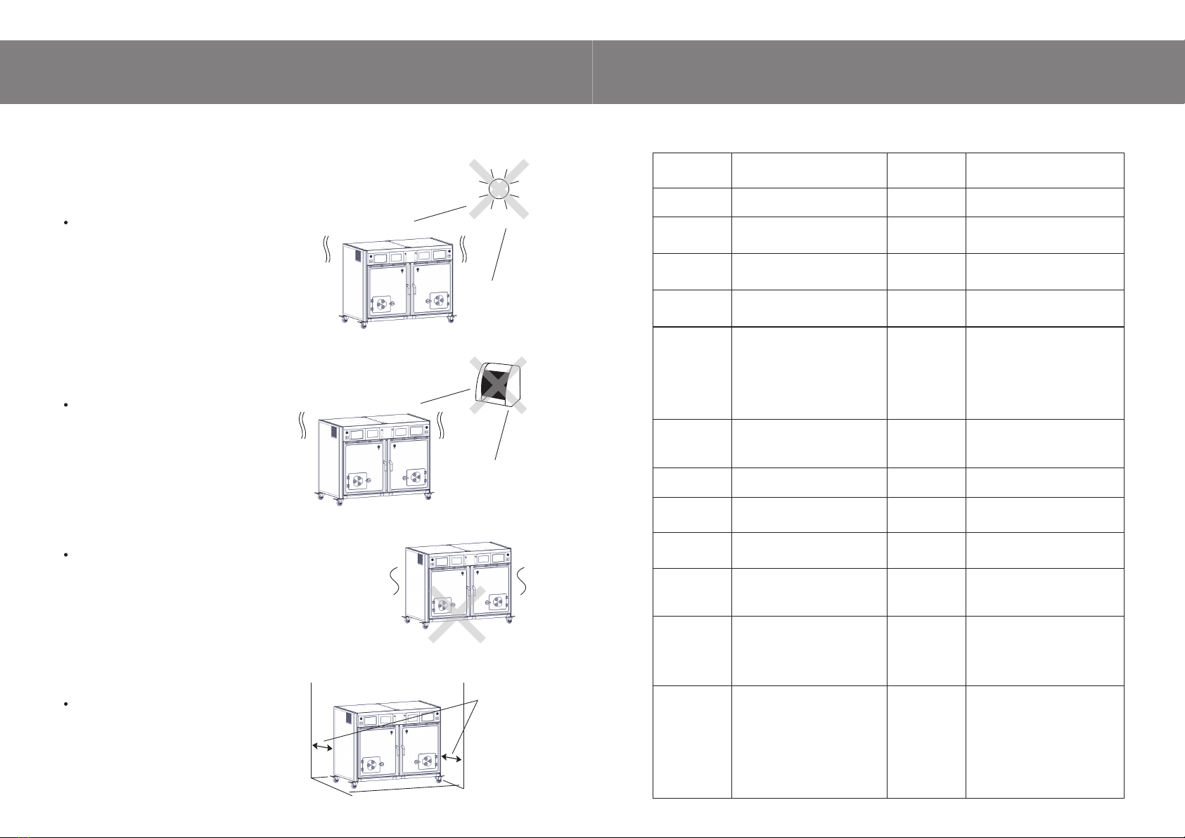
The unit should be used indoors only, in a cool
dry room with stable temperature and humidi-
ty, kept out of direct sunlight, away from any
heat sources, excess moisture or naked
flames.
This unit should only be operated in a
temperature range of 10° to 40° C (50° to 103°
F). It should not be placed in the direct path of
a room air conditioning outlet.
The full unit weighs 300 kg (660lbs); it should
be placed on a level stable floor.
It should never be placed on a soft or uneven
surface like bedding materials or shaggy
carpets.
The unit should be placed in a well-ventilated
position, and all inlets and outlets should be
unobstructed, there should be a 15cm or
6-inch clearance on all sides.
Care should be taken when choosing the working space for this unit.
Product Name
Model Number
Dimension
Weight
Power Supply
Environment
Control
Air Purification
Temperature
Setting Range
Oxygen Concen-
tration Setting
Carbon Dioxide
Monitoring and
Removal
Alarms
Dehumidification
8.4”, 171mmW×128mmH
Resistive
1.3KW
0.5KW
Emergency Ventilation Port
7.2×10⁶pcs/cm3
Negative Ion Generator
Smart Control Needle Type Printer
253nm UV Sterilization
415nm Blue Therapeutic Light
Treatment
≥0.2ml/min, particle size:
0.5 -2μm, noise≤ 40dB(A)
Control Panel
Screen Type
Max. Power
Consumption
Average Power
Consumption
Power Supply
Failure Protection
Negative Ion
Generator
Accessories
Built-in Printer
Ultra-violet
Sterilization
Blue Light
Therapy
Medical
Nebulizer
LED Illumination
Ventilation Fan
Control
Professional Veterinary
Intensive Care Unit
UC-1901M/L/BK
1509mmW×884mmD×1899mmH
(59.5”W×35”D ×75”H)
Approximate 300kg (660lbs)
AC100~120V /220~240V
50/60Hz (Grounded)
4 Compartments Controlled
Separately, Cooling and Heating.
Two Medium Compartments on
Top Tier, One Large Compartment
on Bottom Tier which could be
divided into two medium com-
partments when needed.
Ultra Violet Sterilization, High
Concentration Negative Ion Air
Purification.
-10~40°C (Indoor)
15~38°C, Tolerance at 0.5°C
21~65%, Tolerance at ±1%.
200 -5000PPM,
Tolerance at ±10PPM,
Built-in CO2 Sensor and Remover
Automatic Dehumidification,
High/Middle/Low Three Stages,
High: 45%~50%,
Middle: 40%~44%,
Low: 30%~39%.
O2 Concentration Alarm, Tempe-
rature Alarm, Sensor Alarm, Door
Opening Alarm, CO2
Concentration.
Alarm, Emergency Ventilation Port
Malfunction Alarms.
Soda Lime CO2 Absorption
Powder, Equipment Mount Grid,
Door Shade Curtain.
Working
Condition
Low/Middle/High, Three-Stage Speed
Control.
Defaults:
Oxygen Input On: Low Speed.
Temperature Control: High Speed
Emergency Port Open: High Speed
Ultra-violet Sterilization On: Middle
CO2 Concentration Level Alarm On:
High
Pure White Cold Light for
Examination, 10 Stage Adjustable
Yellow .
Comfort Light for Illumination.
06 07
Operation Guidance Setting Interface
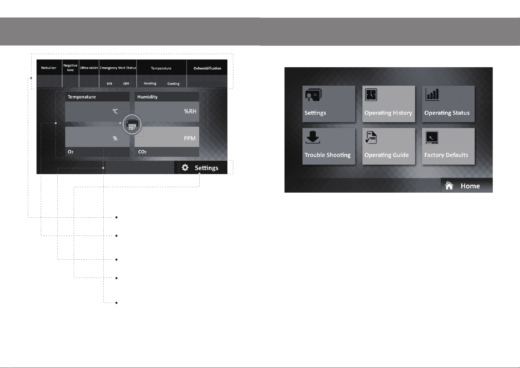
Main Interface Navigation
Operating Status – Indicating the varied functions
running in real time.
Key Parameters – Displaying the key figures,
Temperature, Humidity, O2Density and CO2Density
Trouble Shooting – Instructions with pictures for all
problem solving.
Settings Button – Clicking the “Setting” button; this
will open the detailed setting page. The settings can
now be changed from this page.
Printing Button – Located at the center of the 4 icons
parameter boxes, on the running status display page
pressing and holding the button for 5 seconds will
print the real-time running status instantly.
On this interface, you will find the following functions and displays.
1. Setting Mode
Allows the operator to switch on/off and set all the changeable running parameters for most functions.
2. Operating History
Allowing the operator to view a complete operational status of “Temperature”, “Humidity”, “CO2Density”
and “O2Density”, displayed in intuitive curves, allows up to 72 hours /3 days maximum historical
tracking.
3. Operating Status
Real-time operating status for most parameters.
4. Trouble Shooting
Providing an easy-to-follow on screen step-by-step guide with problem solving solutions with visual
instructions for all “alarming components” and "non-alarming components".
5. Operating Guide
An on-screen Basic Operation Guide with photographs.
6. Factory Defaults
The defaults settings for all main components can only be accessed with the factory pass codes, they
should only be adjusted under the careful guidance from our factory technicians if necessary.

0908
Setting Mode
Temperature
1 2 3
456
7 8 9
+/- 0.
CLR
DEL
Enter
15.0~38.0
25.0
25.0 OFF
OFF
OFF
OFF
OFF
30.0
50
1500
3
Auto
中
0
0
1
9
8
+
-
Humidity
1 2 3
4 5 6
7 8 9
+/- 0.
CLR
DEL
Enter
25.0~50.0
30.0
25.0 OFF
OFF
OFF
OFF
OFF
30.0
50
1500
3
Auto
中
0
0
1
9
8
+
-
1. Temperature Setting
a) Enter “Setting Mode”.
b) Click the existing temperature figure in “Tempera-
ture” bar.
c) Set the desired temperature by clicking the numbers in the
newly opened settings box, within the range of 15 -38 Celsius
Degrees (59 -100.5 Fahrenheit).
d) Click “Enter” to set and save the new value, and then click
the “X” in the top right corner of the settings box to close the
settings box.
2. Humidity Setting
a) Enter “Setting Mode”.
b) Click the existing humidity figure in “Humidity” bar.
c) Set the desired humidity by clicking the numbers in the
newly opened settings box, within the range of 25 -50%, click
the “X” in the top right corner of the settings box to close the
settings box.
Temperature
Humidity
3. Oxygen Density Setting
a) Enter “Setting Mode”.
b) Click the existing oxygen figure in “O2Density” bar.
c) Input the desired oxygen density value by clicking the newly
opened setting box, within the range of 21 -65%.
d) Click “Enter” to set the new oxygen level, click the “X” in the
top right corner of the Settings box to close the settings box.
4. Carbon Dioxide Density Set
a) Enter “Setting Mode”.
b) Click the existing carbon dioxide figure in “CO2Density” bar.
c) Input the desired carbon dioxide density by clicking the
newly displayed setting box, within the range of 200
-2000ppm.
d) Click “Enter” to set the new carbon dioxide level, click the
“X” in the top right corner of the settings box to close the
settings box.
5. Illumination Light Set
a) Enter “Setting Mode”.
b) Click the existing time figure in “Light Timer” bar.
c) Input the desired working time for illumination light by
clicking the newly displayed setting box, within the range of 1
-360 minutes.
d) Click “Enter” to set the illumination light working time, click
the “X” in the top right corner of the settings box to close the
settings box.
6. Light Brightness Set
On “Setting Mode” interface, the light brightness can be
adjusted by pressing either “+” or “-“ button on “Light
Brightness” bar, displayed in the graph here.
Once the level of brightness is set, illumination light will start.
7. Ventilation Fan Control
a) Enter “Setting Mode”.
b) Click the existing fan speed on “Fan Speed” bar, to shift
fan speed through “high”, “middle” and “low”.
O2Density
1 2 3
4 5 6
7 8 9
+/- 0.
CLR
DEL
Enter
21~65
50
25.0
30.0
50
1500
3
Auto
中
+
-
CO2 Density
1 2 3
4 5 6
7 8 9
+/- 0.
CLR
DEL
Enter
200~2000
1500
25.0
30.0
50
1500
3
Auto
中
+
-
Light Timer
1 2 3
4 5 6
7 8 9
+/- 0.
CLR
DEL
Enter
0~360
3
+
-
25.0
30.0
50
1500
3
Auto
中
+
-
25.0
30.0
50
1500
3
Auto
中
+
-
O2Density
CO2Density
Light Brightness
Fan Speed
Light Timer
Remarks: Fan running speed will affect heating or cooling efficiency, please make decisions
according to actual needs based on animal patients status and ambient temperature.
MIDDLE
10 11
OFF
OFF
OFF
OFF
OFF
0
0
1
9
8
OFF
OFF
OFF
OFF
OFF
0
0
1
9
8
OFF
OFF
OFF
OFF
OFF
0
0
1
9
8
OFF
OFF
OFF
OFF
OFF
0
0
1
9
8
9. Exam Light
a) Enter “Setting Mode”.
b) Click the existing time figure in “Exam Light” bar.
c) Input the desired working time for the pure white exam light
by clicking the newly opened displayed setting box, in the range
of 1 -360 minutes.
d) Click “Enter” to set the exam light working time, click the “X” in
the top right corner of the settings box to close the settings box.
e) Switch on exam light when needed by shifting OFF button to
ON as displayed. The light can be switched off by shifting from
ON to OFF at anytime.
10. Blue Light Therapy
a) Enter “Setting Mode”.
b) Click the existing time figure in “Blue Light Therapy” bar.
c) Input the desired working time for blue light by clicking the
displayed setting box, in the range of 1 -360 minutes.
d) Click “Enter” to set the blue light working time, click the “X” in
the top right corner of the settings box to close the settings box.
e) Switch on blue light when needed by shifting OFF button to
ON as displayed below.
Remarks:
When therapeutic blue light is on, exam light and illumination
yellow light will be shut down automatically; once the blue light
finishes working, other lights will resume.
25.0 OFF
OFF
OFF
OFF
OFF
30.0
50
1500
3
Auto
中
0
0
1
9
8
+
-
25.0 OFF
OFF
OFF
OFF
OFF
30.0
50
1500
3
Auto
中
0
33
1
9
8
+
-
25.0
OFF
OFF
OFF
OFF
OFF
30.0
50
1500
3
Auto
中
0
0
1
9
8
+
-
Exam Light
123
456
789
+/- 0.
CLR
DEL
Enter
0~360
30
Blue Light Therapy
1 2 3
4 5 6
7 8 9
+/- 0.
CLR
DEL
Enter
0~360
33
OFF
OFF
OFF
OFF
50
1500
3
Auto
中
0
1
9
8
+
-
8. Emergency Vent Setting
The emergency ventilation port is designed as a fail-safe, for
necessary fresh air in critical situations like a power supply
failure.
The fan is powered by a Lithium battery pack, which will allow several operations without a power
supply from the mains power.
a) Enter “Setting Mode”.
b) Select suitable vent opening mode by shifting the “ON”, “OFF” and “AUTO” on “Emergency Vent
Setting” bar.
Note: There are three working modes of Emergency Vent, ON, OFF and AUTO.
A. ON, means the vent will stay open unconditionally.
B. OFF, means the vent will be shut unless power supply failure is detected, then it will
be opened for fresh air.
OFF mode is NOT recommended to be used.
C. AUTO, means the vent will be opened in the following conditions.
C1: Power supply failure.
C2: O2Density in compartment drops to lower than 15%.
C3: O2 Density ≤25% and CO2Density stabilizes at the level of greater than CO2
Density Alarm setting for over 3 minutes.
C4: O2 Density ≥25% and CO2Density level exceeds 4500ppm.
Blue Light
Therapy
Exam Light
Blue Light
Therapy
MIDDLE
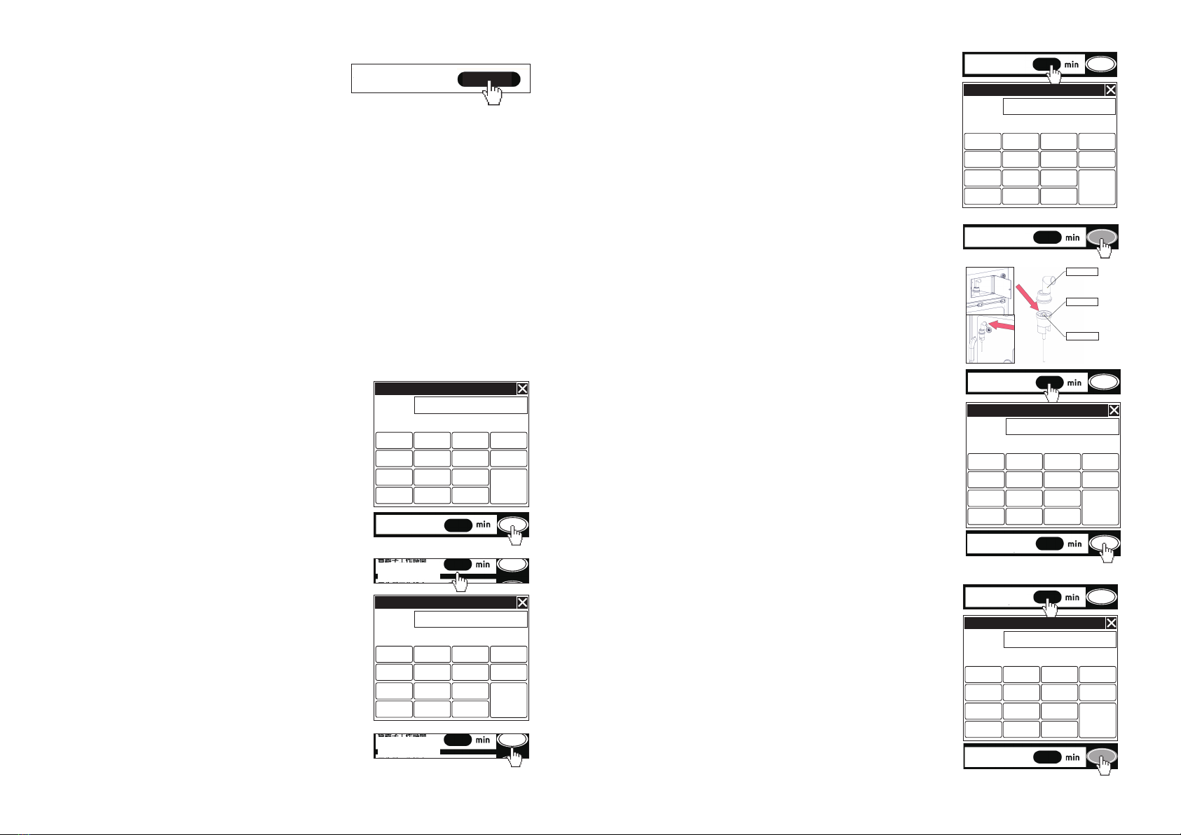
12. Nebulizer and Timer
a) Open the nebulizer chamber door on front control panel of
the machine.
b) Gently take the nebulizer assembly out from the chamber, be
careful not to stretch the pipeline too much.
c) Open nebulizer nozzle cap by twisting counterclockwise.
d) Pour medicine liquid into the medicine cup, replace nozzle
cap clockwise.
e) Attach the cup nozzle part into the silicon port at the left
upper corner of the transparent door.
f) Enter “Setting Mode”.
g) Click the existing time figure in “Nebulizer Timer” bar.
h) Input the desired working time for nebulizer by clicking the
newly opened displayed setting box, in the range of 1 -90
minutes.
i) Click “Enter” to set the nebulization working time; click the “X”
in the top right corner of the settings box to close the settings
box.
j) Turn the nebulizer on when needed by shifting OFF button to
ON as displayed below.
Remarks: During nebulization treatment, cooling, heating and
ventilation functions will shut down, for better preservation of
medicine atmosphere in the compartment.
13. Ultra-violet Timer
a) Enter “Setting Mode”.
b) Click the existing time figure in “Ultra-violet Timer” bar.
c) Input the desired working time for ultra-violet sterilization by
clicking the displayed setting box, in the range of 1 -90 minutes.
d) Click “Enter” to set the ultra-violet sterilization working time;
click the “X” in the top right corner of the settings box to close
the settings box.
e) Switch on ultra-violet sterilization light when needed by
shifting OFF button to ON as displayed below.
Note: There must be No Animals in the unit when this function is
being used.
11. Negative Ion Set
a) Enter “Setting Mode”.
b) Click the existing time figure in “Negative Ion Timer” bar.
c) Input the desired working time for negative ion gener-
ator by clicking the newly opened displayed setting box, in
the range of 0 -72 hours.
d) Click “Enter” to set the negative ion working time; click the
“X” in the top right corner of the settings box to close the
settings box.
e) Switch on negative ion generator when needed by shifting
OFF button to ON as displayed below.
Nozzle cap
Medicine cup
Cone gasket
Nebulizer Timer
1 2 3
4 5 6
7 8 9
+/- 0.
CLR
DEL
Enter
0~90
20
1 2 3
4 5 6
7 8 9
+/- 0.
CLR
DEL
Enter
0~72
2
25.0
NO
NO
ON
OFF
OFF
30.0
50
1500
3
Auto
中
0
0
2
9
8
+
-
25.0
NO
NO
ON
OFF
OFF
30.0
50
1500
3
Auto
中
0
0
2
9
8
+
-
25.0
OFF
OFF
OFF
OFF
OFF
30.0
50
1500
3
Auto
中
0
0
0
9
8
+
-
1 2 3
4 5 6
7 8 9
+/- 0.
CLR
DEL
Enter
0~90
15
25.0
OFF
OFF
OFF
OFF
OFF
30.0
50
1500
3
Auto
中
0
0
1
9
0
+
-
25.0
NO
NO
NO
OFF
ON
30.0
50
1500
3
Auto
中
0
0
2
9
15
+
-
Timer
Timer
25.0
OFF
OFF
OFF
OFF
OFF
30.0
50
1500
3
Auto
中
0
0
0
9
8
+
-
Nebulizer Timer
Nebulizer Timer

12 13
25.0
OFF
OFF
OFF
OFF
OFF
30.0
50
1500
3
Auto
中
0
33
1
9
8
+
-
25.0
OFF
OFF
OFF
OFF
OFF
30.0
50
1500
3
Auto
中
0
33
1
20
8
+
-
14. Printing Intervals Set
a) Enter “Printing Intervals”.
b) Click the existing time figure in “Printing Intervals” bar.
c) Input the suitable printing intervals by clicking the newly
opened setting box, in the range of 0 -60 minutes. Setting it at
0 min will shut down this printing function.
d) On the printing slip, four key parameters can be displayed,
Temperature, Humidity, Oxygen Density and Carbon Dioxide
Density.
e) “Hospital or Clinic” names can be printed on the slip as a
customization option; please contact your local supplier for
more details.
f) Switch on printing function when needed by shifting OFF
button to ON as displayed below.
15. Running Status
On the Running Status page, all real-time running
status will be displayed.
16. CO2Remover Replacement Reminder
Depending on varied types of soda lime powder
from different suppliers, the effective validation
time may be different; the operator can set
17. Parameter Calibrations
The Parameter Calibration needs to be managed
by trained qualified technician, or under the
guidance and supervision of our technicians.
On this page, you can make adjustments to these
parameters below.
Temperature Setting Zero and Full.
Humidity Setting Zero and Full.
Ambient Temperature and Auxiliary Temperature.
CO2Density Setting Zero and Full.
25.0 OFF
OFF
OFF
OFF
OFF
30.0
50
1500
3
Auto
中
0
0
1
9
8
+
-
OFF
0
1 2 3
4 5 6
7 8 9
+/- 0.
CLR
DEL
Enter
0~60
30
25.0 OFF
OFF
OFF
OFF
OFF
30.0
50
1500
3
Auto
中
0
0
1
9
8
+
-
ON
30
CO2
Replacement Reminder RENEW
② ③④
different replacement reminding times accordingly.
At the bottom of the above page for “Running Status”, the estimated CO2remover replacement time
is displayed.
Click the boxes shown above to set effective time for soda lime CO2remover reminder.
In box 4, it shows the elapsed working time from last replacement; box 2 is for resetting the validation
time for different suppliers’ soda lime.
If you are using the soda lime from our company, please click “RENEW” button to set it at 800 hours
after replacing.
Note: It’s highly recommended to use our soda lime to ensure a reliable working efficiency and
service life.
18. History
The running status of four key parameters,
temperature, humidity, CO2density and O2density,
will be recorded every minute.
In our system, the operation history can be tracked
for up to 72 hours /3 days as maximum.
All the curves will be displayed on this interface, you
can click on any of them to enlarge the whole curve
and get more detailed statistics.
19. Operation Guide
All the instructions shown above are also
installed in the control panel system; they can
be found in the Operation Guide page shown.
The instructions are displayed with detailed
wording and photos.
20. Accessories Mount Installation
This stainless steel wire grid is designed for
mounting all necessary accessories, such as IV
pole, infusion pump, syringe pump, monitor, etc.
Please insert the bottom foot into the fixture hole
on top of the large compartment first, then match
and insert the top pin into the triangle connector
between the two medium compartments as
indicated by the picture.
21. Door Shade Curtain Installation
A slide track and four hooks are installed on top of
the transparent doors on each compartment, to
hang the shade curtains helping cut out light and
noise transmissions to the compartment and calm
the patients.
No other function can be set when the unit is being disinfected. The disinfecting process can be
cancelled at any time returning the unit to its previous settings. All other lights will be cancelled and all
functions will be stopped during the disinfection process.
O2Density Setting Zero and Full.
Note: You need a pass code to enter this page, please contact your local supplier or service center
for further assistance.
1514
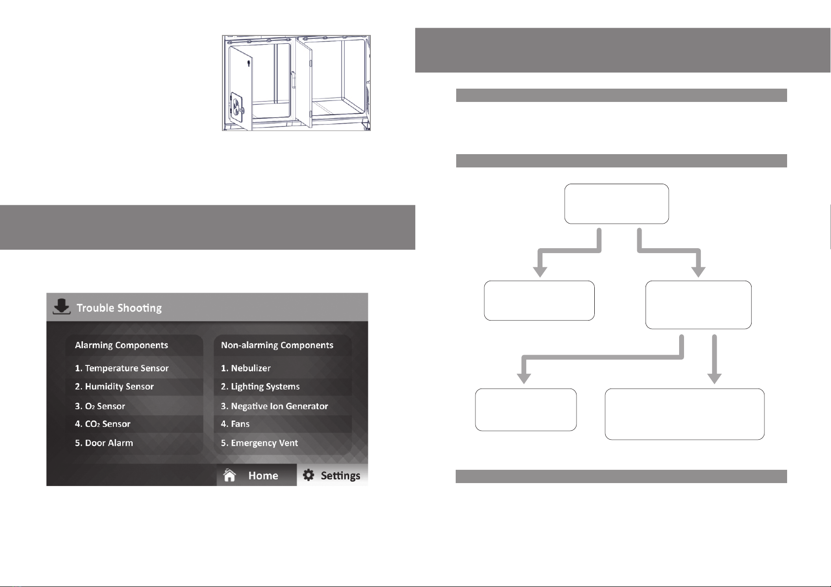
Troubleshooting
Alarming Components
On the Trouble Shooting page, most common potential faults are displayed, with both alarming
components and non-alarming ones combined.
Please follow the instructions below if you have a fault.
22. Large Compartment Divider Application
With this very unique and practical feature, the large
compartment can be divided into two separately
controlled medium compartments.
By loosening the two latches on top of the front
column in the middle of the large compartment, it can
be pulled out at the top then up to remove, then the
middle hidden divider will be exposed.
Pull out the middle divider gently; the two medium
compartments will become one large unit. The detector switch on the back wall of the compartment
will be released, the left sided control panel will be shut down, and the right-sided control panel will
now manage the whole large compartment.
When the middle divider is replaced, both control panels on left and right compartments will start to
operate.
1. Temperature Sensor & Humidity Sensor Replacement
Both Temperature and humidity sensors can be found can be found at the innermost top corner of the
compartment. Open the cover grid, both sensors will be exposed, please replace the faulty compo-
nent according to the instructions displayed on control panel screen.
2. O2Sensor Replacement
If O2
.
isn’t
is
The door alarm will be triggered if the front door stays open for more than 3 minutes.
Please check the front door status when alarm sounds; close the door securely to eliminate the alarm
when needed.
3. Door Alarm
16 17
4. CO2Sensor
1. Nebulizer
2. Lighting Systems 3. Negative Ion Generator
If CO2
isn’t
is
Non-alarming components
a) Please check if foreign objects or drug residue have blocked the medicine cup or nebulizer pipeline.
b) Open and remove the top cover on the ICU compartment to expose internal components.
c) Please find the nebulizer pump and check if it’s damaged; replace it when needed.
Note: There is a backup nebulizer pump inside, please double check and diagnose which one is
broken before replacing.
Open the grid at the top corner nearest to the
door hinge.
Locate faulty light component and replace it
when needed.
Open and remove the top cover on ICU
compartment to expose internal components.
Please find the negative ion generator, check if
it’s broken.
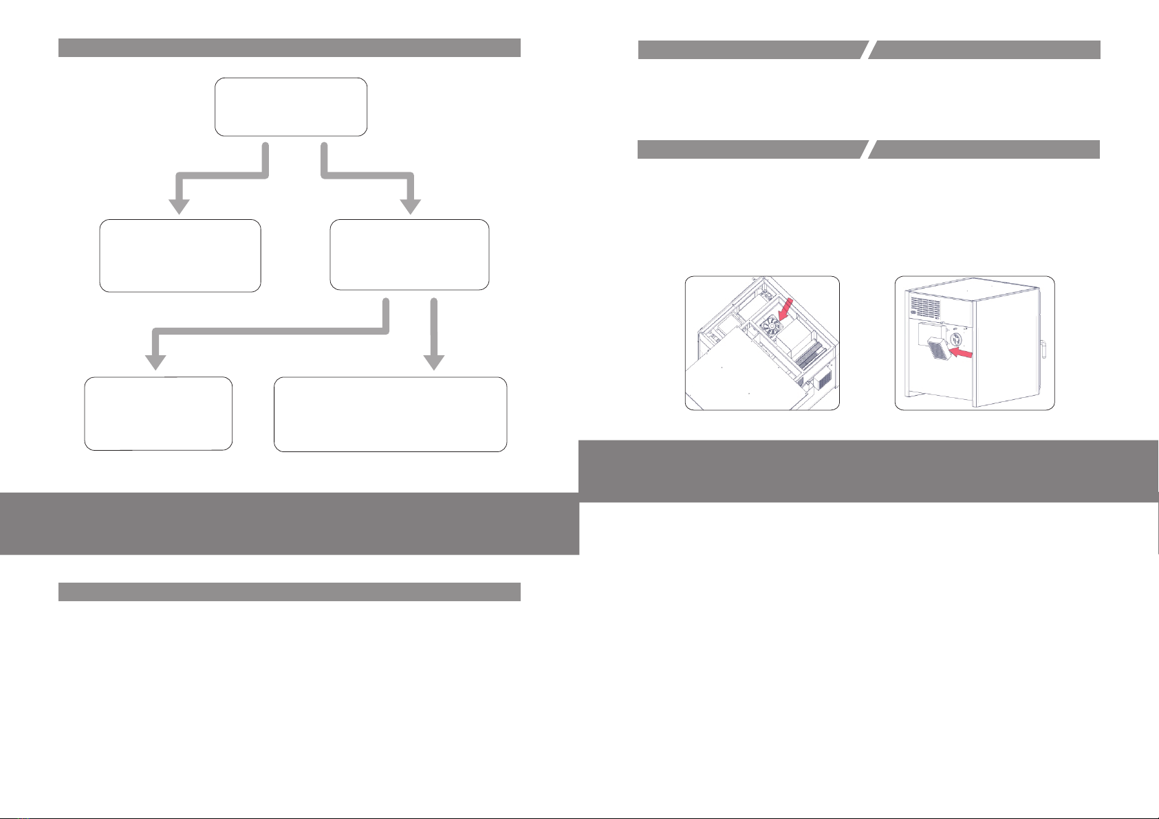
Open and remove the protective cover on the
emergency ventilation fan on the back of the
unit, as indicated in Figure below.
Replace the entire emergency vent assembly.
Open the top cover of the ICU unit; locate the
fan assembly as indicated by the red arrow in
Figure below.
Replace the fans when necessary.
Note: The PTC heating assemblies will need to
be removed before replacing the fans.
4. Fans 5. Emergency Vent
Both inside and outside of the machine can be wiped clean regularly with a mild cleaning agent that
is non-abrasive, such as “Aseptic Plus” clinical grade disinfectant.
Clean the control panel with a mild household cleaner and non-abrasive cloth or sponge at least one
time each week.
All inlet vents should be vacuumed regularly to remove any dust; they can be wiped clean with a soft
cloth using a mild cleaning agent. We suggest the filters are removed and washed clean regularly,
then allowed to dry before replacing.
In between usages, the compartment should be cleaned with a soft cloth or sponge using a mild
cleaning agent; then turn the ultra-violet sterilization on for at least 3 minutes to disinfect the whole
unit.
Regular testing of the emergency vent should be done between usages; the unit can simply be
powered off to check if the vent opens.
Maintenance And Cleaning
This manual suits for next models
2
Table of contents
Other aeolus Pet Care Product manuals

aeolus
aeolus BTS-132TE User manual

aeolus
aeolus BTS-131E User manual

aeolus
aeolus TD-907 User manual

aeolus
aeolus BTS-130E User manual

aeolus
aeolus UC-1801-RCK User manual

aeolus
aeolus PW-001 User manual

aeolus
aeolus KaniStar Warmology WMS-1501 User manual

aeolus
aeolus UC-1701 User manual

aeolus
aeolus BTS-138E User manual

aeolus
aeolus TD-905 User manual


Popular Pet Care Product manuals by other brands


BIGLEASH
BIGLEASH VIBRATION TRAINER V-10 owner's guide

Premier Pet
Premier Pet GAL00-16809 product manual

Roverpet
Roverpet KK2 Assembly instructions

Richell
Richell 94193 instruction manual

SportDOG
SportDOG YARD TRAINER 100 Operating and basic training guide

Merry Products
Merry Products CAT WASHROOM BENCH MPCB006 manual


