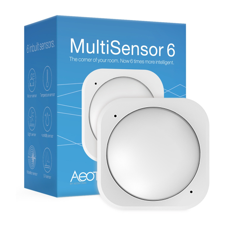
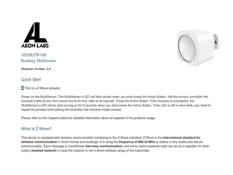
Aeon Labs MultiSensor 6 User manual

Aeon Labs MultiSensor 6
(Z-wave MultiSensor)

Change history
Revision
Date
Change Description
1
/
2
3
/20
1
4
Initial
draft
.
2
5/26/
20
15
U
pdate
3
7/01/2015
U
pdate
4
7/21/2015
U
pdate
(V1.06)
5
8/11/
20
15
Add more details for configura
tion parameters

Aeon Labs MultiSensor 6
Engineering Specifications and Advanced Functions for Developers
Aeon Labs MultiSensor is a routing binary sensor device based on Z-Wave routing slave library V6.51.06.
MultiSensor can be included and operated in any Z-wave network with other Z-wave certified devices
from other manufacturers and/or other applications. All non-battery operated nodes within the network
will act as repeaters regardless of vendor to increase reliability of the network.
It also supports Security Command Class and has the AES-128 bit security encryption built right in. While
a Security enabled Controller is needed in order to fully use the security feature.
If the MultiSensor is included into a SIS or SUC Z-wave network, it will be associated to SIS or SUC
automatically.
If PIR motion sensor is triggered, the MultiSensor will send a Basic set (0xFF) to associated devices. The
PIR motion sensor will then become inactive. After an interval time (configurable), the PIR motion
sensor will wake up and can detect motion again. The Multisensor will send basic set (0x00) if the PIR
motion sensor is not triggered for the interval time (configurable).
As soon as MultiSensor is removed from a z-wave network it will restore itself into factory settings.
1. Library and Co and Classes
1.1 SDK: 6.51.06
1.2 Library
Basic Device Class:
BASIC_TYPE_ROUTING_SLAVE
Generic Device class:
GENERIC_TYPE_ SENSOR_MULTILEVEL
Specific Device Class: SPECIFIC_TYPE_ ROUTING_MULTILEVEL_SENSOR
1.3 Co ands Class
Included Non
-
Secure
Included Secure
Node Info Fra e COMMAND_CLASS_ZWAVEPLUS_INFO V2,
COMMAND_CLASS_VERSION V2,
COMMAND_CLASS_MANUFACTURER_SPECIFIC,
COMMAND_CLASS_ASSOCIATION_GRP_INFO,
COMMAND_CLASS_ASSOCIATION V2,
COMMAND_CLASS_POWERLEVEL V1,
COMMAND_CLASS_NOTIFICATION_V3,
COMMAND_CLASS_WAKE_UP V2,
COMMAND_CLASS_BATTERY V1,
COMMAND_CLASS_SENSOR_BINARY V1,
COMMAND_CLASS_SENSOR_MULTILEVEL_V5,
COMMAND_CLASS_CONFIGURATION V1,
COMMAND_CLASS_SECURITY V1,
COMMAND_CLASS_FIRMWARE_UPDATE_MD_V2,,
COMMAND_CLASS_MARK,
COMMAND_CLASS_DEVICE_RESET_LOCALLY,
COMMAND_CLASS_ZWAVEPLUS_INFO V2
COMMAND_CLASS_VERSION V2
COMMAND_CLASS_WAKE_UP V2
COMMAND_CLASS_MANUFACTURER_SPECIFIC V2
COMMAND_CLASS_SECURITY V1
COMMAND_CLASS_DEVICE_RESET_LOCALLY V1
COMMAND_CLASS_MARK V1

Security
Co and
Supported Report
Fra e
- COMMAND_CLASS_ZWAVEPLUS_INFO,
COMMAND_CLASS_VERSION,
COMMAND_CLASS_MANUFACTURER_SPECIFIC,
COMMAND_CLASS_WAKE_UP,
COMMAND_CLASS_ASSOCIATION_GRP_INFO,
COMMAND_CLASS_ASSOCIATION,
COMMAND_CLASS_POWERLEVEL,
COMMAND_CLASS_NOTIFICATION_V3,
COMMAND_CLASS_BATTERY,
COMMAND_CLASS_SENSOR_BINARY,
COMMAND_CLASS_SENSOR_MULTILEVEL_V5,
COMMAND_CLASS_CONFIGURATION,
COMMAND_CLASS_SECURITY,
COMMAND_CLASS_FIRMWARE_UPDATE_MD_V2
2. Technical Specifications
Operating distance: Up to 500 feet/150 metres outdoors.
Operating te perature: 0 to
℃
40 .
℃
Relative hu idity: 8%RH to 80%RH.
3. Fa iliarize Yourself with Your MultiSensor
3.1 Interface
4. All Functions of Each Trigger
4.1 Function of Z-Wave Button
Tri
gger
Description
Click one time 1. Send non-security Node Info fra e.
2. Add MultiSensor into z-wave network:
1. Power on MultiSensor. The MultiSensor’s LED will blink slowly when you short press the Action Button.
2. Let the primary controller into inclusion mode (If you don’t know how to do this, refer to its manual).
3. Press the Action Button.
4. If the inclusion is success, MultiSensor’s LED will be kept turning on for 8 seconds when you short press the
Action Button. If the LED is still in slow blink, in which you need to repeat the process from step 2.

3. Re ove MultiSensor fro Z-wave network:
1. Power on MultiSensor. The MultiSensor’s LED will be kept turning on for 8 seconds when you short press
the Action Button.
2. Let the primary controller into exclusion mode (If you don’t know how to do this, refer to its manual).
3. Press the Action Button.
4. If the exclusion is success, MultiSensor’s LED will blink slowly when you short press the Action Button. If
MultiSensor
’
s
LED still
keeps on
status,
i
n which you need to
repeat the process from step 2.
Short press 2 times
within 1 second
1. Send Security Node Info fra e.
2. Add MultiSensor into z-wave network:
1. Power on MultiSensor. The MultiSensor’s LED will blink slowly when you short press the Action Button.
2. Let the primary controller into inclusion mode (If you don’t know how to do this, refer to its manual).
3. Press the Action Button.
4. If the inclusion is success, MultiSensor’s LED will be kept turning on for 8 seconds when you short press the
Action Button. If the LED is still in slow blink, in which you need to repeat the process from step 2.
3. Re ove MultiSensor fro Z-wave network:
1. Power on MultiSensor. The MultiSensor’s LED will be kept turning on for 8 seconds when you short press
the Action Button.
2. Let the primary controller into exclusion mode (If you don’t know how to do this, refer to its manual).
3. Press the Action Button.
4. If the exclusion is success, MultiSensor’s LED will blink slowly when you short press the Action Button. If
MultiSensor
’
s
LED still
keeps on
status,
in which you need to
repeat the process from step 2.
Press and hold for 3
seconds
Enable/disable wake up for 10 minutes.
(When it is enabled, the orange Led will fast blink)
Press and hold for
20 seconds
Reset MultiSensor to factory Default:
1. Press and hold the Action Button for 20 seconds.
2. If holding time more than one second, the LED will blink faster and faster. If holding time more than 20
seconds, the LED will be on for 2 seconds, which indicates reset is success, otherwise please repeat step 2.
Note:
1, This procedure should only be used when the primary controller is inoperable.
2, Reset MultiSensor to factory default settings, it will:
a ), let the MultiSensor to be excluded in Z-Wave network;
b), delete the Association setting, power measure value, Scene Configuration settings;
c),
restore
the
Configuration
s
ettings to
the
default.
5. Special Rule of Each Co and
5.1 Z-Wave Plus Info Report Co and Class
Para eter
Value
Z-Wave Plus Version 1
Role Type 6(ZWAVEPLUS_INFO_REPORT_ROLE_TYPE_SLAVE_ALWAYS_ON)
Node Type 0 (ZWAVEPLUS_INFO_REPORT_NODE_TYPE_ZWAVEPLUS_NODE)
Installer Icon Type
0x0C07 (
ICON_TYPE_SPECIFIC_SENSOR_NOTIFICATION_HOME_SECURITY
)
User Icon Type
0x0C07 (
ICON_TYPE_SPE
CIFIC_SENSOR_NOTIFICATION_HOME_SECURITY
)

5.2 Association Co and Class
MultiSensor supports 1 association group.
Group 1 is assigned to the Lifeline association group and can add max 5 association nodes.
When the PIR motion sensor is triggered, the MultiSensor will send Basic Set (0xFF) to the associated
nodes. If no any PIR motion on an interval time (configurable), the MultiSensor will send Basic Set (0x00)
to the associated nodes.
The automatically report of temperature, humidity, luminance and ultraviolet (configurable) also can be
sent to associated nodes.
5.3 Association Group Info Co and Class
5.3.1 Association Group Info Report Co and Class
Profile: General: NA (Profile MSB=0, Profile LSB=0)
5.3.2 Association Group Na e Report Co and Class
Group 1: Lifeline
5.3.3 Association Group Co and List Report
Co and List Report:
20 01 30 03 80 03 31 05 71 05 84 07.
COMMAND_CLASS_BASIC
BASIC_SET
COMMAND_CLASS_SENSOR_BINARY SENSOR_BINARY_REPORT
COMMAND_CLASS_BATTERY BATTERY_REPORT
COMMAND_CLASS_SENSOR_MULTILEVEL
SENSOR_MULTILEVEL_REPORT
COMMAND_CLASS_NOTIFICATION_V3 NOTIFICATION_REPORT_V3
COMMAND_CLASS_WAKE_UP
WAKE_UP_NOTIFICATION
5.4 Manufacturer Specific Report
Para eter
Value
Manufacturer ID 1
US/EU/AU=0x00 CN=0x01
Manufacturer ID 2 US/EU/AU=0x86 CN=0x6A
Product Type ID 1 EU=0x00, US=0x01, AU=0x02 CN=0x1D (2 )
Product Type ID 2 0x03
Product ID 1
0x00
Product ID 2
0x64 (100)
5.6 Configuration Set Co and Class
7 6 5 4 3 2 1 0
Command Class = COMMAND_CLASS_CONFIGURATION
Command = CONFIGURATION_SET
Parameter Number
Default
Reserved
Size
Configuration Value 1(MSB)
Configuration Value 2
………
Configuration Value n(LSB)
Parameter Number Definitions (8 bit):

Para eter
Nu ber
Hex / Deci al
Description Default Value Size
2 (0x02) Enable/Disable waking up for 10 minutes when re-power on (battery mode) the
MultiSensor.
1. Value = 0, disable.
2.
Value =others
,
enable
.
0 1
3 (0x03) 1. The default PIR time is 4 minutes. The Multisensor will send BASIC SET CC
(0x00) to the associated nodes if no motion is triggered again in 4 minutes.
2. Range: 10~3600.
Note:
(1), The time unit is second if the value range is in 10 to 255.
(2), If the value range is in 256 to 3600, the time unit will be minute and its value
should follow the below rules:
a), Interval time =Value/60, if the interval time can be divided by 60 and
without remainder.
b), Interval time= (Value/60) +1, if the interval time can be divided by 60 and
has remainder.
(3), Other values will be ignored.
240 2
4 (0x04) Enable/disable the function of motion sensor.
1. Value=0, disable.
2. Value=1, enable, the current PIR sensitivity level=1. (minimum level)
Value=2, enable, the current PIR sensitivity level=2.
Value=3, enable, the current PIR sensitivity level=3.
Value=4, enable, the current PIR sensitivity level=4.
Value=
5
, enable
, the current PIR
sensitivity
level=5. (maximum level)
5 1
5 (0x05) Which command would be sent when the motion sensor triggered.
1. Value=1, send Basic Set CC.
2. Value=2, send Sensor Binary Report CC.
1 1
3 (0x27) Configure low battery value.
Value=10 to 50.(10% to 50%)
20 (%) 1
40 (0x28) Enable/disable the selective reporting only when measurements reach a certain
threshold or percentage set in 41-44 below. This is used to reduce network
traffic. (0 == disable, 1 == enable)
0 1
41 (0x2 ) Threshold change in temperature to induce an automatic report.
Note:
1. The unit is Fahrenheit for US version, Celsius for EU/AU version.
2. The value contains one decimal point. E.g. if the value is set to 20, the
threshold value =2.0
℃
(EU/AU version) or 2.0
℉
(US version). When the
current temperature gap is more then 2.0, which will induce a temperature
report to be sent out.
20 2
42 (0x2A) Threshold change in humidity to induce an automatic report.
Note:
1. The unit is %.
2. The default value is 10, which means that if the current humidity gap is
more than 10%, it will send out a humidity report.
10 2

43 (0x2B) Threshold change in luminance to induce an automatic report. 100 (LUX) 2
44 (0x2C) Threshold change in battery level to induce an automatic report.
Note:
1. The unit is %.
2. The default value is 10, which means that if the current battery level gap is
more than 10%, it will send out a battery report.
10 (%) 2
45 (0x2D) Threshold change in ultraviolet to induce an automatic report. 2 1
46 (0x2E) Enable/disable to send the alarm report of low temperature(<-15
℃
)
Value=0, disable.
Value=1, enable (The MultiSensor will send a report of Multi Level Temperature
CC to controller if the current temperature is less than -15
℃
).
Note: The battery activity will be reduced at low temperatures (-15 degrees
Celsius and below), which will lead to the product may not work normally. It is
recommended to use USB power at low temperatures.
0 1
100 (0x64) Set 101-103 to default. - -
101 (0x65) Which report needs to be sent in Report group 1 (See flags in table below). 241 4
102 (0x66) Which report needs to be sent in Report group 2 (See flags in table below). 0 4
103 (0x67) Which report needs to be sent in Report group 3 (See flags in table below). 0 4
110 (0x6E) Set 111-113 to default. - -
111 (0x6F) The interval time of sending reports in Report group 1 (Valid values 0x05-
0x28DE80).
1. The unit of interval time is second if USB power.
2. If battery power, the minimum interval time is 60 minutes by default, for
example, if the value is set to be more than 5 and less than 3600, the interval
time is 60 minutes, if the value is set to be more than 3600 and less than 7200,
the interval time is 120 minutes. You can also change the minimum interval time
to 4 minutes via setting the interval value(3 bytes) to 240 in Wake Up Interval Set
CC.
3600 (seconds) 4
112 (0x70) The interval time of sending reports in Report group 2 (Valid values 0x05-
0x28DE80).
Note:
1. The unit of interval time is second if USB power.
2. If battery power, the minimum interval time is 60 minutes by default, for
example, if the value is set to be more than 5 and less than 3600, the interval
time is 60 minutes, if the value is set to be more than 3600 and less than 7200,
the interval time is 120 minutes. You can also change the minimum interval time
to 4 minutes via setting the interval value(3 bytes) to 240 in Wake Up Interval Set
CC.
3600 (seconds) 4

113 (0x71) The interval time of sending reports in Report group 3 (Valid values 0x05-
0x28DE80).
1. The unit of interval time is second if USB power.
2. If battery power, the minimum interval time is 60 minutes by default, for
example, if the value is set to be more than 5 and less than 3600, the interval
time is 60 minutes, if the value is set to be more than 3600 and less than 7200,
the interval time is 120 minutes. You can also change the minimum interval time
to 4 minutes via setting the interval value(3 bytes) to 240 in Wake Up Interval Set
CC.
3600 (seconds) 4
201 (0xC ) Temperature calibration (the available value range is [-100,100] or [-
10.0
℃
,10
℃
] ).
Note:
1. The value contains one decimal point. E.g. if the value is set to 20, the
calibration value is 2.0
℃
(EU/AU version) or 2.0
℉
(US version)
2. The calibration value = standard value - measure value.
E.g. If measure value =25.3
℃
and the standard value = 23.2
℃
, so the
calibration value= 23.2
℃
- 25.3
℃
= -2.1
℃
(0xEB).
If the measure value =30.1
℃
and the standard value = 33.2
℃
, so the calibration
value= 33.2
℃
- 30.1
℃
=3.1
℃
(0x1F).
0 1
202 (0xCA) Humidity sensor calibration (the available value range is [-50, 50]).
The calibration value = standard value - measure value.
E.g. If measure value =80RH and the standard value = 75RH, so the calibration
value= 75RH – 80RH= -5RH (0xFB).
If the measure value =85RH and the standard value = 0RH, so the calibration
value= 0RH – 85RH=5RH (0x05).
0 1
203 (0xCB) Luminance sensor calibration (the available value range is [-1000, 1000]).
The calibration value = standard value - measure value.
E.g. If measure value =800Lux and the standard value = 750Lux, so the
calibration value= 750 – 800= -50 (0xFFCE).
If the measure value =850Lux and the standard value = 00Lux, so the calibration
value= 0
0
–
85
0
=5
0
(0x00
32
).
0 2
204 (0xCC) Ultraviolet sensor calibration (the available value range is [-10, 10]).
The calibration value = standard value - measure value.
E.g. If measure value = and the standard value = 8, so the calibration value= 8 –
= -1 (0xFE).
If the measure value =7 and the standard value = , so the calibration value= –
7=2 (0x02).
0 1
252 (0xFC) Enable/disable Configuration Locked (0 =disable, 1 = enable). 0 1
255 (0xFF) Value=0x55555555
、
Default=1
、
Size=4
Reset to factory default setting and removed from the z-wave network
N/A 4
2.Reset to factory default setting N/A 1
Configuration Values for Parameter 101-103
:
7 6 5 4 3 2 1 0

configuration
Value 1(MSB)
Reserved
configuration
Value 2
Reserved
configuration
Value 3
Reserved
configuration
Value 4(LSB)
Luminance Humidity Temperature Ultraviolet
Reserved Reserved Reserved Battery
Reserved
Reserved bits or bytes must be set to zero.
Table of contents
Other Aeon Labs Accessories manuals
Popular Accessories manuals by other brands

Baxi
Baxi 7703233 Installation, commissioning and user instructions
System Sensor
System Sensor 2251TEM Installation and maintenance instructions
White Rodgers
White Rodgers F145RF-1600 installation instructions
Selve
Selve commeo Wind Sensor Operating instruction

IK Multimedia
IK Multimedia iRig Pre HD user manual
Teledyne
Teledyne Everywhereyoulook CCD261-04 quick start guide
Wasserstein
Wasserstein Premium Smart Water, Temperature, and Humidity... user manual

fontastic
fontastic Renz10 user manual
Vega
Vega VEGAPULS 61 operating instructions
IFM Electronic
IFM Electronic efector150 operating instructions
PNI
PNI SmartHome WP850 user manual

Veris
Veris HAWKEYE 708 installation instructions
