Aeon Labs Aeotec Water Sensor 6 User manual

Page 1
Aeon Labs Water Sensor 6
(Z-Wave Water Sensor)

Page 2
Change history
Revision Date Change Description
1 01/05/2017 Initial dra t.
2 03/28/2017 Update
3 04/07/2017 Update
4 04/27/2017 Update

Page 3
Aeon Labs Water Sensor 6
Engineering Specifications and Advanced Functions for Developers
Aeon Labs Water Sensor 6 is a binary sensor device based on Z-Wave enhanced 232 slave library
o V6.51.09.
The Water Sensor 6 contains 2 Sensor ports, which allow you to connect 2 water probes on the
Main Sensor unit to detect the presence and absence o water or detect whether there is the water
leak in some places o your home.
It can be included and operated in any Z-Wave network with other Z-Wave certi ied devices rom
other manu acturers and/or other applications. All non-battery operated nodes within the network
will act as repeaters regardless o vendor to increase reliability o the network.
The Water Sensor 6 is a security Z-Wave plus device, so a security enabled controller is needed or
take ull advantage o all unctionally or the Sensor. It also supports the Over The Air (OTA) eature
or the product’s irmware upgrade.
As soon as Water Sensor 6 is removed rom a Z-Wave network, it will be restored into de ault
actory setting.
1 Library and Command Classes:
1 1 SDK: 6 51 09
1 2 Library:
Basic Device Class
:
BASIC_TYPE_ROUTING_SLAVE
Generic Device class
:
GENERIC_TYPE_SENSOR_NOTIFICATION
Speci ic Device Class: SPECIFIC_TYPE_NOTIFICATION_SENSOR
1 3 Commands:
Non-Security Inclusion Security Inclusion
Node Info
List
COMMAND_CLASS_ZWAVEPLUS_INFO_V2
COMMAND_CLASS_VERSION_V2
COMMAND_CLASS_MANUFACTURER_SPECIFIC_V2
COMMAND_CLASS_ASSOCIATION_GRP_INFO_V1
COMMAND_CLASS_ASSOCIATION_V2
COMMAND_CLASS_POWERLEVEL_V1
COMMAND_CLASS_NOTIFICATION_V7
COMMAND_CLASS_WAKE_UP_V2
COMMAND_CLASS_BATTERY_V1
COMMAND_CLASS_SENSOR_MULTILEVEL_V5
COMMAND_CLASS_CONFIGURATION_V1
COMMAND_CLASS_MULTI_CHANNEL_V4
COMMAND_CLASS_MULTI_CHANNEL_ASSOCIATIO
N_V3
COMMAND_CLASS_FIRMW ARE_UPDATE_MD_V2
COMMAND_CLASS_DEVICE_RESET_LOCALLY_V1
COMMAND_CLASS_MARK_V1
COMMAND_CLASS_ZWAVEPLUS_INFO_V2
COMMAND_CLASS_VERSION_V2
COMMAND_CLASS_MANUFACTURER_SPECIFIC_V
2
COMMAND_CLASS_W AKE_UP_V2
COMMAND_CLASS_SECURITY_V1
COMMAND_CLASS_DEVICE_RESET_LOCALLY_V1
COMMAND_CLASS_MARK_V1

Page 4
Security
Supported
Command
Class List
COMMAND_CLASS_ASSOCIATION_G RP_INFO_V1
COMMAND_CLASS_ASSOCIATION_V2
COMMAND_CLASS_POWERLEVEL_V1
COMMAND_CLASS_NOTIFICATION_V7
COMMAND_CLASS_BATTERY_V1
COMMAND_CLASS_SENSOR_MUL TILEVEL_V5
COMMAND_CLASS_CONFIGURATION _V1
COMMAND_CLASS_MULTI_CHANNEL_V4
COMMAND_CLASS_MULTI_CHANNEL_ASSOCIATI
ON_V3
COMMAND_CLASS_FIRMWARE_UPDATE_MD_V2
2 Technical Specifications
Operating distance: Up to 492 eet/150 meters outdoors.
3
Familiarize yourself with your Water Sensor
3 1 Interface
4 All Functions of Each Trigger
4 1 Function of Action Button
Trigger Description
Click one time 1 Send non-security Node Info frame
2 Add Water Sensor into Z-Wave network(non-security inclusion):

Page 5
1. Power on Water Sensor. The Water Sensor’s LED will blink slowly when you short press the
Action Button.
2. Let the primary controller into inclusion mode (I you don’t know how to do this, re er to its
manual).
3. Press the Action Button.
4. I the inclusion is success, Water Sensor’s LED will be kept turning on or 8 seconds when you
short press the Action Button. I the LED is still in slow blink, in which you need to repeat the
process rom step 2.
3 Remove Water Sensor from Z-wave network:
1. Power on Water Sensor. The Water Sensor’s LED will be kept turning on or 8 seconds when
you short press the Action Button.
2. Let the primary controller into exclusion mode (I you don’t know how to do this, re er to its
manual).
3. Press the Action Button.
4. I the exclusion is success, Water Sensor’s LED will blink slowly when you short press the Action
Button. I Water Sensor’s LED still keeps on status, in which you need to repeat the process rom
step 2.
Quick press 2
times within 1
second
1 Send Security Node Info frame
2 Add Water Sensor into z-wave network(
Security inclusion
):
1. Power on Water Sensor. The Water Sensor’s LED will blink slowly when you short press the
Action Button.
2. Let the primary controller into inclusion mode (I you don’t know how to do this, re er to its
manual).
3. Press the Action Button.
4. I the inclusion is success, Water Sensor’s LED will be kept turning on or 8 seconds when you
short press the Action Button. I the LED is still in slow blink, in which you need to repeat the
process rom step 2.
3 Remove Water Sensor from Z-wave network:
1. Power on Water Sensor. The Water Sensor’s LED will be kept turning on or 8 seconds when
you short press the Action Button.
2. Let the primary controller into exclusion mode (I you don’t know how to do this, re er to its
manual).
3. Press the Action Button.
4. I the exclusion is success, Water Sensor’s LED will blink slowly when you short press the Action
Button. I Water Sensor’s LED still keeps on status, in which you need to repeat the process rom
step 2.
Press and hold
or 3 seconds
Enable/disable wake up for 10 minutes
(When it is enabled, the orange Led will ast blink)
Press and hold
or 20 seconds
Reset Water Sensor to factory default:
1. Press and hold the Action Button or 20 seconds.
2. I holding time more than one second, the LED will blink aster and aster. I holding time more than
20 seconds, the LED will be on or 2 seconds, which indicates reset is success, otherwise please
repeat step 2.
Note:

Page 6
1, This procedure should only be used when the primary controller is inoperable.
2, Reset Water Sensor to actory de ault settings, it will:
a ), let the Water Sensor to be excluded in Z-Wave network;
b), delete the Association settings;
c), restore the Con iguration settings to the de ault.
5 Special rule of each command
5 1
Basic Command Class
When the water sensor is triggered, it will send the Basic Set 0x00/0xFF (con igured by parameter 0x58 and
0x59) to the associated nodes in association group 3 or 4.
Basic Report = 0x00, Water Leak Cleared.
Basic Report = 0xFF, Water Leak Detected
5 2
Z-Wave Plus Info Report Command Class
Parameter Value
Z-Wave Plus Version 1
Role Type 6 (ZWAVEPLUS_INFO_REPORT_ROLE_TYPE_SLAVE_ALWAYS_ON)
Node Type 0 (ZWAVEPLUS_INFO_REPORT_NODE_TYPE_ZWAVEPLUS_NODE)
Installer Icon Type 0x0C07 (ICON_TYPE_SPECIFIC_SENSOR_NOTIFICATION_HOME_SECURITY)
User Icon Type 0x0C07 (ICON_TYPE_SPECIFIC_SENSOR_NOTIFICATION_HOME_SECURITY)
5 3
Manufacturer Specific Report
Parameter Value
Manu acturer ID 1 AEON LABS=0x00
Manu acturer ID 2 AEON LABS=0x86
Product Type ID 1 EU=0x00, US=0x01, AU=0x02 CN=0x1D (29)
Product Type ID 2 0x02
Product ID 1 0x00
Product ID 2 0x7A (122)
5 4
Association Command Class
Water Sensor 6 supports 4 association groups and can add max 5 nodes or every group.
Association
Group
Nodes
Send
Mode
Send commands
Group 1
(Li eline)
[1,5] Single Cast 1. Send Battery Report or Multilevel Sensor Report (con igured
by parameter 0x65 and 0x6F).
2. Send Noti ication Report when water leak is detected.
Note: When having a classic Node ID association on this
group, the Water Sensor will send the “Water leak detected”
noti ication i any o the probes detect water and “event
cleared” noti ication i none o the probe longer detects a

Page 7
water leak.
3. Send Device Reset Locally when it is reset.
Group 2 [1,5] Single Cast Send con iguration 0x88 report:
Group 3 [1,5] Single Cast Send Basic Set (con igured by parameter 0x58) to the associated
nodes in Group 3 when the Sensor probe 1 is triggered.
Group 4 [1,5] Single Cast Send Basic Set (con igured by parameter 0x59) to the associated
nodes in Group 4 when the Sensor probe 2 is triggered.
5 5
Association Group Info Command Class
5.5.1 Association Group Name Report
Group Name ASSIC Code
Group 1 Li eline 4C 69 66 65 6C 69 6E 65
Group 2 Retransmit 52 65 74 72 61 6E 73 6D 69 74
Group 3 ON/OFF Control(Sensor Probe 1) 4F 4E 2F 4F 46 46 20 43 6F 6E 74 72 6F 6C 28 4C 65 61
6B 20 50 72 6F 62 65 20 31 29
Group 4 ON/OFF Control(Sensor Probe 2) 4F 4E 2F 4F 46 46 20 43 6F 6E 74 72 6F 6C 28 4C 65 61
6B 20 50 72 6F 62 65 20 32 29
5.5.2 Association Group Info Report
Group Profile Vg1
Group 1 General:Li eline 01 01 00 00 01 00 00 00
Group 2 General:NA 01 02 00 00 00 00 00 00
Group 3 Noti ication:WaterAlarm01 01 03 00 71 05 00 00 00
Group 4 Noti ication:WaterAlarm02 01 04 00 71 05 00 00 00
5.5.3 Association Group Command List Report
Group Command Class Command Code
Group 1 COMMAND_CLASS_CONFIGURATION CONFIGURATION_REPORT 70 06
COMMAND_CLASS_BATTERY BATTERY_REPORT 80 03
COMMAND_CLASS_SENSOR_MULTILE
VEL
SENSOR_MULTILEVEL_REPORT 31 05
COMMAND_CLASS_NOTIFICATION NOTIFICATION_REPORT 71 05
COMMAND_CLASS_DEVICE_RESET_LO
CALLY
DEVICE_RESET_LOCALLY_NOTIFICATION
5A 01
Group 2 COMMAND_CLASS_CONFIGURATION CONFIGURATION_REPORT 70 06
Group 3 COMMAND_CLASS_BASIC BASIC_SET 20 01
Group 4 COMMAND_CLASS_BASIC BASIC_SET 20 01
5 6 Notification Command Class
Notification Type Notification Events
Heat Alarm 0x04 Previous Events cleared 0x00
Overheat detected, unknown Location 0x02

Page 8
Under heat detected, Unknown Location 0x06
Water Alarm 0x05 Previous Events cleared 0x00
Water Leak detected, Unknown Location 0x02
Home Security 0x07 Previous Events cleared 0x00
Tampering Product covering removed 0x03
5 7 Multichannel Command Class
It supports 2 Multi Channel Endpoints.
1. Multi Channel endpoint 1 capability:
71 - COMMAND_CLASS_NOTIFICATION
5E - COMMAND_CLASS_ZWAVEPLUS_INFO
59 - COMMAND_CLASS_ASSOCIATION_GRP_INFO
98 - COMMAND_CLASS_SECURITY
I there is the multi channel endpoint association, the Multi Channel Endpoint 1 can be used to
send the encapsulated report to the associated nodes in association Group 3 when the sensor
probe 1 is triggered.
2. Multi Channel endpoint 2 capability:
71 - COMMAND_CLASS_NOTIFICATION
5E - COMMAND_CLASS_ZWAVEPLUS_INFO
59 - COMMAND_CLASS_ASSOCIATION_GRP_INFO
98 - COMMAND_CLASS_SECURITY
I there is the multi channel endpoint association, the Multi Channel Endpoint 2 can be used to
send the encapsulated report to the associated nodes in association Group 4 when the sensor
probe 2 is triggered.
5 8 Multilevel Sensor Command Class
Sensor Type Scale
Air Temperature 0x01 Celsius ( )
℃
0x00
Fahrenheit ( )
℉
0x01
5 9 Configuration Command Class
7 6 5 4 3 2 1 0
Command Class = COMMAND_CLASS_CONFIGURATION
Command = CONFIGURATION_SET
Parameter Number
De ault Reserved Size
Con iguration Value 1(MSB)
Con iguration Value 2
………

Page 9
Con iguration Value n(LSB)
Parameter Number De initions (8 bit):
Parameter
Number
Hex/
Decimal
Description Default Value Size
0x02 (2) Enable/disable wake up or 10 minutes state when re-power on the
Sensor
0 = Disable,
1 = Enable.
0 1
0x08 (8) Set the timeout to go into the sleep state a ter the Wake Up
Noti ication was sent out.
[15, 255]
30 1
0x09 (9) Get the current power mode
Value 1: 0 = USB power, 1 = Battery power.
Value 2: 0 = Sleeping mode a ter re-power on, 1 = keep awake or 10
minutes a ter re-power on, 2 = always awake state.
Note: This parameter is a Get-only parameter.
- 2
0x0A (10) Set the alarm time or the Buzzer when the sensor is triggered.
Value 1: the time o Buzzer keeping OFF state (MSB)
Value 2: the time o Buzzer keeping OFF state (LSB)
Value 3: the time o Buzzer keeping ON state (MSB)
Value 4: repeated cycle o Buzzer alarm.
Note: one cycle is equal to the Buzzer rom ON state to OFF state.
0x001E0A0A 4
0x27 (39) Set the low battery value.
Range: 10% to 50%.
20 1
0x30 (48) Enable/disable the sensor report
Bit =0, the corresponding sensor report is disabled.
Bit =1, the corresponding sensor report is enabled.
1 1
0x31 (49) Set the upper limit value (overheat).
Value 1: temperature value (MSB)
Value 2: temperature value (LSB)
Value 2: 0 = Celsius unit, 1 = Fahrenheit unit.
Value 4: reserved.
US version:
0x04100100 (104
℉
).
Other versions:
0x01900000 (40
℃
).
4
0x32 (50) Set the lower limit value (under heat).
Value 1: temperature value (MSB)
Value 2: temperature value (LSB)
Value 2: 0 = Celsius unit, 1 = Fahrenheit unit.
Value 4: reserved.
US version:
0x01400100 (32
℉
).
Other versions:
0x00000000 (0
℃
).
4
0x39 (57) Set the recover limit value o temperature sensor.
Note:
1. When the current measurement <= (Upper limit – Recover limit),
the upper limit report is enabled and then it would send out a
sensor report when the next measurement is more than the
upper limit. A ter that the upper limit report would be disabled
again until the measurement <= (Upper limit – Recover limit).
US version:
0x1401(2.0
℉
)
Other version:
0x1400 (2.0
℃
)
2

Page 10
2. When the current measurement >= (Lower limit + Recover limit),
the lower limit report is enabled and then it would send out a
sensor report when the next measurement is less than the lower
limit. A ter that the lower limit report would be disabled again until
the measurement >= (Lower limit + Recover limit).
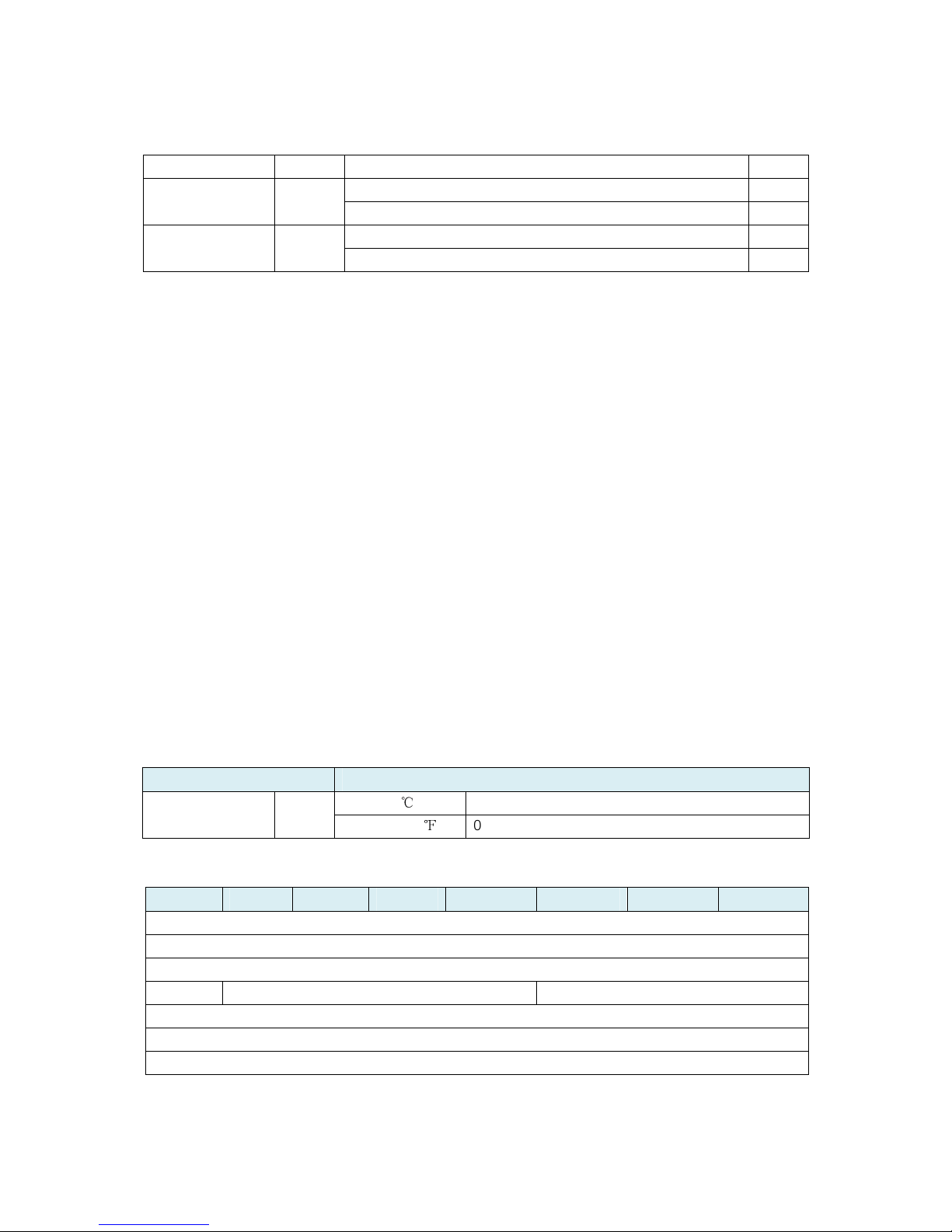
3. High byte is the recover limit value. Low byte is the unit
(0x00=Celsius, 0x01=Fahrenheit).
4. Recover limit range: 1.0 to 25.5
℃
/
℉
(0x0100 to 0xFF00 or 0x0101
to 0xFF01).
E.g. The de ault recover limit value is 2.0
℃
/
℉
(0x1400/0x1401), when
the measurement is less than (Upper limit – 2), the upper limit report
would be enabled one time or when the measurement is more than
(Lower limit + 2), the lower limit report would be enabled one time.
0x40 (64) Set the de ault temperature unit.
0 = Celsius unit.
1 = Fahrenheit unit.
US version: 0x01
Other versions: 0x00
1
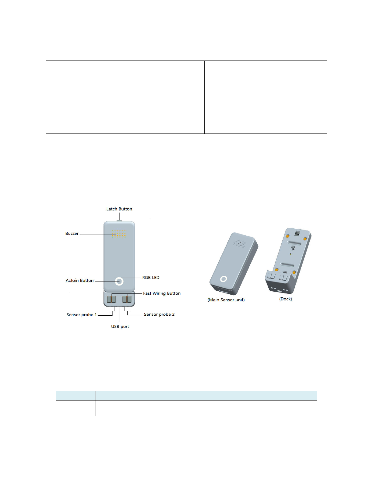
0x54 (84) The state o tilt sensor
0 = the Water Sensor main unit is in horizontal direction.
1 = the Water Sensor main unit is in vertical direction.
Note: this parameter is a Get-only parameter.
- 1
0x56 (86) Enable/ disable the buzzer.
0 = disable.
1 = enable.
1 1
0x57 (87) To set which sensor is triggered the buzzer will alarm.
1 = I the Water leak is triggered, the buzzer will alarm.
2 = I the vibration is triggered, the buzzer will alarm.
4 = I the tilt sensor is triggered, the buzzer will alarm.
16 = I the under heat is triggered, the buzzer will alarm.
32 = I the overheat is triggered, the buzzer will alarm.
Note: i the value = 1+2+4+16+32=55, which means i any sensor is
triggered, the buzzer will alarm.
55 1
0x58 (88) To set which value o the Basic Set will be sent to the associated
nodes in association Group 3 when the Sensor probe 1 is triggered.
0 = Send nothing.
1 = Presence o water, send Basic Set 0xFF, absence o water, send
Basic Set 0x00.
2 = Presence o water, send Basic Set 0x00, absence o water, send
Basic Set 0xFF.
0 1
0x59 (89) To set which value o the Basic Set will be sent to the associated
nodes in association Group 4 when the Sensor probe 2 is triggered.
0 = Send nothing.
1 = Presence o water, send Basic Set 0xFF, absence o water, send
Basic Set = 0x00.
2 = Presence o water, send Basic Set 0x00, absence o water, send
Basic Set 0xFF.
0 1
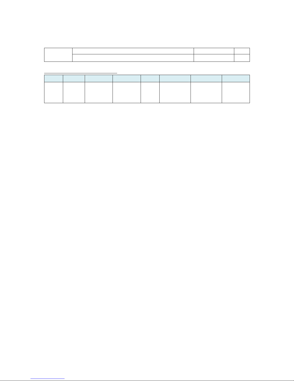
0x5E (94) To set which power source level is reported via the Battery CC.
0 = report the USB power level.
0 1

Page 11
1 = report the CR123A battery level.
0x65 (101) To set what unsolicited report would be sent to the Li eline group.
0 = Send Nothing.
1 = Battery Report.
2 = Multilevel sensor report or temperature.
3 = Battery Report and Multilevel sensor report or temperature.
3 1
0x6F (111) Set the interval time or sending the unsolicited report that con igured
by parameter 0x65. (Valid values 0x05-0x28DE80)
Note:
1. The unit o interval time is second i USB power.
2. I battery power, the minimum interval time is equal to Wake Up
interval set by the Wake Up CC.
3600 4
0x87 (135) To set which sensor report can be sent when the water leak event is
triggered and i the receiving device is a non-multichannel device.
0 = Send nothing.
1 = Send noti ication report to association group 1.
2 = Send con iguration 0x88 report to association group 2.
3 = Send noti ication report to association group 1 and Send
con iguration 0x88 report to association group 2.
1 1
0x88 (136) When the parameter 0x87 is set to 2 or 3, it can get the sensor probes’
status through this con iguration value.
I Bit 0 = 0, which means absence o water is triggered by probe 1.
I Bit 0 = 1, which means presence o water is triggered by probe 1.
I Bit 1 = 0, which means absence o water is triggered by probe 2.
I Bit 1 = 1, which means presence o water is triggered by probe 2.
Bit 2-7 = reserved.
Note:
This parameter is a Get- only parameter.
_ 1
0xC9 (201) Temperature calibration (the available value range is [-128,127] or [-
12.8 ,
℃
12.7 ]).
℃
Note:
1. High byte is the calibration value. Low byte is the unit
(0x00=Celsius, 0x01=Fahrenheit)
2. The calibration value (high byte) contains one decimal point. E.g.
i the value is set to 20 (0x1400), the calibration value is 2.0
℃
(EU/AU version) or i the value is set to 20 (0x1401), the calibration
value is 2.0
℉
(US version)
3. The calibration value (high byte) = standard value - measure
value.
E.g. I measure value =25.3
℃
and the standard value = 23.2
℃
, so
the calibration value= 23.2
℃
- 25.3
℃
= -2.1
℃
(0xEB).
I the measure value =30.1
℃
and the standard value = 33.2
℃
, so the
calibration value= 33.2
℃
- 30.1
℃
=3.1
℃
(0x1F).
US version: 0x0001.
Other versions:
0x0000.
2
0xFC (252) Enable/disable Con iguration Locked.
0 = Disable.
1 = Enable.
0 1
0xFF (255) Value=0x55555555
、
De ault=1
、
Size=4 N/A 4

Page 12
Reset to actory de ault setting and removed rom the z-wave network
Reset to actory de ault setting N/A 1
Parameter number equals 0x30:
Bit 7 Bit 6 Bit 5 Bit 4 Bit 3 Bit 2 Bit 1 Bit 0
_ _
Noti ication
Report or
Overheat
alarm
Noti ication
Repor t or
Under heat
alarm
_
Con igur ation
Report or Tilt
sensor
Noti ication
Report or
Vibration
event
Noti ication
Repor t or
Water Leak
event
Table of contents
Other Aeon Labs Accessories manuals