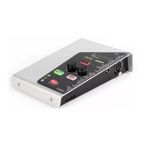
AEQ Phoenix Stratos User manual

AEQ PHOENIX STRATOS
USER’S MANUAL
ED. 02/16
V. 1.1 - 05/12/2016
Firmware Versions: Micro 6.00 / DSP 3.33 / FPGA 3.04 or higher
ISDN Module: Micro 1.01 / TA 6.00
Software Version: AEQ ControlPHOENIX 2.2.1.7 or higher

AEQ PHOENIX STRATOS
2
CONTENTS
1. INTRODUCTION.......................................................................................................................6
1.1. General description............................................................................................................6
1.2. Functional specifications....................................................................................................6
1.3. Available encoding modes.................................................................................................7
1.4. Block diagram. ...................................................................................................................8
1.5. Compatibility with other AEQ codecs.................................................................................9
1.6. Compatibility with other manufacturers’ codecs. ...............................................................9
2. PHYSICAL DESCRIPTION OF THE UNIT.............................................................................10
2.1. Description of the front panel and controls......................................................................10
2.1.1. Multifunction display..............................................................................................10
2.1.2. Screen-associated keys / Contextual buttons.......................................................10
2.1.3. Browsing encoder. ................................................................................................10
2.1.4. ESC button............................................................................................................10
2.1.5. Alphanumeric keypad. ..........................................................................................11
2.1.6. VU meters.............................................................................................................11
2.1.7. Communication status control information............................................................11
2.1.8. Headphones volume.............................................................................................12
2.1.9. Monitoring headphones output. ............................................................................12
2.2. Description of the rear panel and connections. ...............................................................13
2.2.1. Analog line stereo inputs.......................................................................................13
2.2.2. Analog line stereo outputs. ...................................................................................13
2.2.3. AES/EBU inputs/outputs.......................................................................................14
2.2.4. GPIO connector. ...................................................................................................14
2.2.5. Interfaz X.21/V.35. ................................................................................................15
2.2.6. COM connector.....................................................................................................16
2.2.7. Ethernet port. ........................................................................................................16
2.2.8. ISDN port. .............................................................................................................17
2.2.9. Power supply.........................................................................................................17
3. INTERNAL MENU DESCRIPTION. MANUAL CONTROL. ...................................................18
3.1. SYSTEM menu. ...............................................................................................................19
3.1.1. CALL REGISTER menu........................................................................................19
3.1.2. CONTACTS menu. ...............................................................................................21
3.1.2.1. INSERT...................................................................................................21
3.1.2.2. DEL. ........................................................................................................23
3.1.2.3. Editing a contact......................................................................................23
3.1.3. AUDIO SETTINGS menu......................................................................................24
3.1.3.1. CODEC CHANNEL 1 SETTINGS menu.................................................24
3.1.3.2. CODEC CHANNEL 2 SETTINGS menu.................................................26
3.1.4. ANALOG AUDIO SETTINGS menu......................................................................26
3.1.5. INTERFACES menu. ............................................................................................27
3.1.5.1. ISDN interface.........................................................................................27
3.1.5.2. Net 1 interface.........................................................................................30
3.1.5.2.1. RTP Point to Point..................................................................30
3.1.5.2.2. DIRECT SIP. ..........................................................................32
3.1.5.2.3. PROXY SIP............................................................................33
3.1.5.2.4. NAT TRAVERSAL submenu..................................................35
3.1.5.3. Net 2 interface.........................................................................................39
3.1.5.4. V35 interface...........................................................................................39
3.1.6. CHANNELS menu.................................................................................................39
3.1.6.1. BACK UP submenu.................................................................................42
3.1.6.2. AUTORECALL MODE submenu. ...........................................................43
3.1.7. MAINTENANCE menu..........................................................................................43
3.1.8. SETTINGS menu..................................................................................................44
3.1.8.1. Audible call notification............................................................................44

AEQ PHOENIX STRATOS
3
3.1.8.2. Date and time..........................................................................................44
3.1.8.3. Ethernet port configuration......................................................................45
3.1.8.4. GPIOs configuration (GPIO Settings). ....................................................45
3.1.8.5. RS-232 Ancillary Data.............................................................................47
3.1.8.6. Remote configuration..............................................................................47
3.1.9. SIP PROVIDERS menu........................................................................................47
3.1.10. SIP CODECS PROFILES menu.........................................................................48
3.2. HPHONES menu. ............................................................................................................49
3.3. VUMETERS menu...........................................................................................................50
3.4. CALL menu......................................................................................................................50
4. CONFIGURATION AND OPERATION OPTIONS DESCRIPTION. REMOTE CONTROL... 54
4.1. Individual codec control window. .....................................................................................54
4.2. IP interface connection modes.........................................................................................56
4.2.1. PROXY SIP...........................................................................................................56
4.2.2. DIRECT SIP..........................................................................................................58
4.2.3. RTP Point to Point (RAW).....................................................................................59
4.2.3.1. Sending audio to multiple destinations: Broadcast, Multicast and
Multiple Unicast.......................................................................................60
4.3. NAT TRAVERSAL. ..........................................................................................................62
4.3.1. Operation without NAT: “OFF (there is no NAT)“. ................................................62
4.3.2. Manual NAT: ”MANUAL (router configuration)”....................................................62
4.3.3. AUTO 1 (local network audio)...............................................................................64
4.3.4. AUTO 2 (local network audio)...............................................................................64
4.3.5. AUTO 3 (audio over internet)................................................................................64
4.3.6. AUTO 4 (audio over internet)................................................................................64
4.4. FEC modes and reception buffer configuration...............................................................64
4.5. V35 interface configuration..............................................................................................65
4.6. ISDN (ISDN1) communications interface configuration...................................................66
4.7. Coding selection...............................................................................................................66
4.8. Ethernet Port configuration..............................................................................................67
4.9. RS-232 Ancillary (End-to-end data channel)...................................................................68
4.10. SNMP configuration.......................................................................................................69
4.11. Password configuration..................................................................................................70
5. QUICKSTART USER’S GUIDE. MANUAL CONTROL. ........................................................71
5.1. PHOENIX STRATOS connections...................................................................................71
5.1.1. Power supply.........................................................................................................71
5.1.2. Audio.....................................................................................................................71
5.1.3. Communication interfaces. ...................................................................................71
5.2. Powering up the codec. ...................................................................................................72
5.3. Establishing an ISDN communication..............................................................................72
5.3.1. Finalizing an ISDN communication.......................................................................73
5.3.2. Reception and acceptance of an ISDN communication. ......................................73
5.4. Establishing a V.35 communication.................................................................................74
5.4.1. Finalizing a V.35 communication..........................................................................75
5.5. Establishing an IP communication...................................................................................75
5.5.1. Establishing an IP communication in RTP mode using SmartRTP......................76
5.5.1.1. Finalizing an IP communication in RTP mode........................................77
5.5.2. Establishing an IP communication in PROXY SIP mode......................................77
5.5.2.1. Finalizing an IP communication in PROXY SIP mode............................78
5.5.2.2. Receiving and accepting an IP communication in PROXY SIP mode....79
5.5.3. Establishing an IP communication in DIRECT SIP mode.....................................80
5.5.3.1. Finalizing an IP communication in DIRECT SIP mode...........................81
5.5.3.2. Receiving and accepting an IP communication in DIRECT SIP mode...81
6. QUICKSTART USER’S GUIDE. REMOTE CONTROL. ........................................................83
6.1. Equipment connections....................................................................................................83
6.1.1. Power supply.........................................................................................................83

AEQ PHOENIX STRATOS
4
6.1.2. Communications interfaces...................................................................................83
6.2. Powering up the codec. ...................................................................................................83
6.3. Setting up a computer to control the unit.........................................................................84
6.4. Audio................................................................................................................................84
6.5. Establishing an ISDN communication..............................................................................84
6.5.1. Finalizing an ISDN communication.......................................................................87
6.5.2. Receiving and accepting an ISDN communication...............................................87
6.6. Establishing a V35 communication..................................................................................88
6.6.1. Finalizing a V35 communication...........................................................................89
6.7. Establishing an IP communication...................................................................................90
6.7.1. Establishing an IP communication in RTP mode using SmartRTP......................90
6.7.1.1. Finalizing an IP communication in RTP mode........................................92
6.7.2. Establishing an IP communication in PROXY SIP mode......................................93
6.7.2.1. Finalizing an IP communication in PROXY SIP mode............................96
6.7.2.2. Receiving and accepting an IP communication in PROXY SIP mode....96
6.7.3. Establishing an IP communication in DIRECT SIP mode.....................................97
6.7.3.1. Finalizing an IP communication in DIRECT SIP mode.........................100
6.7.3.2. Receiving and accepting an IP communication in DIRECT SIP mode. 100
7. CONTROL TERMINAL OVER WEB BROWSER. ...............................................................102
7.1. Upgrading the equipment firmware................................................................................102
7.2. Configuring the MAC address associated with the Ethernet interface. .........................104
7.3. Technical Assistance Service and on-line manuals.......................................................104
7.4. Saving and loading configurations.................................................................................105
7.5. Screen capture...............................................................................................................105
7.6. GPOs and GPIs configuration........................................................................................106
7.7. Status menu...................................................................................................................106
7.8. SNMP.............................................................................................................................107
7.8.1. Getting the Phoenix STRATOS MIB file. ............................................................107
7.9. Remotely rebooting the equipment................................................................................107
8. TECHNICAL SPECIFICATIONS*.........................................................................................108
9. A.E.Q. WARRANTY..............................................................................................................110
ANNEXE A: GENERAL CHARACTERISTICS OF ENCODING MODES................................111
ANNEXE B: CONNECTING PHOENIX STRATOS TO ISDN NATIONAL-1........................... 113
ANNEXE C: PROTOCOLS ASSOCIATED WITH COMMUNICATIONS OVER IP NETWORKS
. .115
C1. Circuit switching versus packet switching......................................................................115
C1.1. Circuit switching...................................................................................................115
C1.1.1. Advantages:...........................................................................................115
C1.1.2. Disadvantages:......................................................................................116
C1.2. Packet switching..................................................................................................116
C1.2.1. Switching Modes: ..................................................................................116
C1.2.2. Advantages:...........................................................................................116
C1.2.3. Disadvantages:......................................................................................117
C2. IP Protocol......................................................................................................................117
C2.1. IP addresses........................................................................................................118
C2.2. Unicast vs. Multicast............................................................................................118
C3. RTP Protocol..................................................................................................................119
C3.1. PHOENIX STRATOS default configuration.........................................................119
C4. SIP Protocol....................................................................................................................119
C4.1. Working modes....................................................................................................120
C4.2. Possible work scenarios......................................................................................121
C4.3. PHOENIX STRATOS default configuration.........................................................122
C5. STUN protocol................................................................................................................122
ANNEXE D: PORTS USED BY PHOENIX EQUIPMENT. ....................................................... 125
ANNEXE E: APPLICATION NOTES GUIDE. ..........................................................................126

AEQ PHOENIX STRATOS
5
E1. Internet connection using standard cable access. .........................................................126
Application note NA0A..................................................................................................126
Application note NA0B..................................................................................................126
Application note NA0C..................................................................................................126
Application note NA0D..................................................................................................126
Application note NA0E..................................................................................................126
Application note NA0F. .................................................................................................126
E2. Special applications using different kinds of Internet physical accesses, or point to point
connections.....................................................................................................................126
Application note NA1.....................................................................................................126
Application note NA2.....................................................................................................126
Application note NA3.....................................................................................................126
Application note NA4.....................................................................................................126
Application note NA5.....................................................................................................126
Application note AN5B..................................................................................................126
ANNEXE F: ADDITIONAL INFORMATION. ............................................................................127

AEQ PHOENIX STRATOS
6
1. INTRODUCTION.
1.1. General description.
AEQ PHOENIX STRATOS is a multiformat, multi-algorithm dual channel audiocodec designed
for stationary rack-mounted applications, like links between studios, STL or mobile equipment
connections. Each one of the two channels is stereo, so actually the unit houses two stereo
codecs with independent AES/EBU digital and analog inputs and outputs.
PHOENIX STRATOS is a rackmounted audiocodec offering the options of working over ISDN,
V35/X21 and IP networks. When used over the IP communications interface, it is fully
compatible with the EBU-TECH 3326 technical specification issued by the EBU N/ACIP working
group. This specification was developed to guarantee compatibility between devices made by
different manufacturers for professional quality audio contribution applications over IP networks.
PHOENIX STRATOS enables its users to work simultaneously over two channels with
professional quality in independent dual mono format or in stereo, or combination of both to
several different destinations.
PHOENIX STRATOS is designed to ensure interoperability with existing and future
communications equipment developed by AEQ and other manufacturers, thanks to the large
number of interfaces and of encoding algorithms it implements, and to the possibility of easily
bringing them up to date as the market evolves.
We recommend you reading this manual and “AEQ ControlPHOENIX” application user’s
manual carefully and completely before using the unit, although chapter 5 offers a
quickstart user’s guide.
1.2. Functional specifications.
-Management of two full-duplex channels (dual mono or stereo) over several possible
communication interfaces: dual IP, V.35/X21 and ISDN.
-Inputs:
•Dual Stereo analog audio input 4 x XLR female. 9Kohm. Electronic balancing.
Line level.
•Digital audio input. DB15 connector. Dual AES/EBU interface with SRC
-Outputs:
•2 stereo analog audio outputs. 4 x XLR male. Output impedance <100 ohm.
Electronic balancing. Line level.
•Digital audio outputs. Two digital AES/EBU audio outputs. It is possible to
synchronize the output with the sampling frequency of the input.
•Headset output. 1 x ¼” stereo jack with volume control on front panel.
-Synchronism: each output extracts it from the channel or alternatively its AES/EBU
input.
-IP Interface. Ethernet Port. Audio and control interface over IP. LAN 10/100 base T
RJ45 connector.
-PHOENIX STRATOS implements SIPv2 for the IP interface according to RFC-3261 and
RFC-3264.
-AEQ offers the “SmartRTP” call initiation protocol in order to greatly simplify the
operation of the unit.
-AEQ also offers the services of its 2 own SIP servers (one of them working as
main server and the other one as backup server) at no additional cost. More
information in section ANNEXE C.
-V.35 interface over DB25 connector.

AEQ PHOENIX STRATOS
7
1.3. Available encoding modes.
The encoding modes available will vary according to the communication interface or module
selected to establish the connection.
We recommend consulting ANNEXE A to see a detailed description, as well as additional
information on these encoding modes.
•OPUS
oMode: Mono / Stereo
oBit rate: 12Kbps / 20Kbps / 32Kbps / 64Kbps / 128Kbps /192Kbps
oSampling rate: 48KHz
•G.711 A-Law or µ-Law mono
oMode: Mono
oBit rate: 64Kbps
•G.722
oMode: Mono
oBit rate: 64Kbps
•AEQ LD+ *
oMode: Mono / Stereo
oBit rate: 64Kbps / 128Kbps / 192Kbps / 256Kbps / 384Kbps
oSampling rate: 16KHz / 32KHz / 48KHz
•MPEG-1/2 LII (MP2) ***
oMode: Mono / Stereo / Dual / JStereo
oBit rate: 64Kbps / 128Kbps /192Kbps / 256Kbps / 384Kbps
oSampling rate: 16KHz / 24KHz / 32KHz / 48KHz
•AAC-LC ****
oMode: Mono / Stereo / MS Stereo
oBit rate: 32Kbps / 64Kbps / 96Kbps / 128Kbps / 192Kbps / 256Kbps
oSampling rate: 24KHz / 32KHz / 48KHz
•AAC-LD ****
oMode: Mono / Stereo / MS Stereo
oBit rate: 32Kbps / 64Kbps / 96Kbps / 128Kbps / 192Kbps / 256Kbps
oSampling rate: 48KHz
•PCM
oMode: Mono / Stereo
oBit rate: between 384 and 2304Kbps
oSampling rate: 32KHz / 48KHz
oBits per sample: 12 (DAT) / 16 / 20 / 24
•Hybrid mode 1
oTX: MPEGL2_64_48
oRX: G722
•Hybrid mode 2
oTX: G722
oRX: MPEG1-LII_64_48
•AUTOSYNC (only for ISDN and V35)
* Proprietary mode, exclusive for AEQ Phoenix, which combines very high quality and low
delay.
** Only the 64 and 128Kbps modes are available for ISDN communications and all the 64,
128 and 256Kbps modes for V35.
*** The 64 and 128Kbps modes over ISDN interface include the option of carrying a
continuous data channel at 9600 bps.
**** AAC-LC and AAC-LD are optional modes. For more information, please consult AEQ
Sales Department or authorized AEQ distributors.
Operation with two AAC simultaneously not supported.
NOTE: Other different encoding modes can be taken into account according to specific needs of
each client.

AEQ PHOENIX STRATOS
8
1.4. Block diagram.
The internal design of the unit is organized in various functional modules that work together to
make the Phoenix STRATOS audiocodec a complete communications platform. The block
diagram below gives a simplified view of the distribution of these modules on the mainboard of
the equipment, as well as a brief description of the associated functions.
Phoenix STRATOS internal distribution detail
-The audio board contains all the audio input and output electronics, both analog and
digital, as well as the V.35/X21, IP & ISDN communication interfaces. It also includes a
serial port for high level debugging applications and for connecting other equipment for
carrying auxiliary data.
-The power supply module is responsible for converting the AC input into the various DC
voltages needed inside the device.
-The board containing the FPGA electronics also provides the interface toward the
microprocessor modules (CPU) and DSP, all of which form the processing and real
control core of the unit.
-The front panel consists of an OLED display showing the control and configuration
menu as well as the set of buttons and indicators for operating the equipment, including
the alphanumeric keypad and the VU meters.
CONNECTORS
& REAR PANNEL
RDSI/ISDN
INTERFACE
IP
INTERFACE
ANALOG & DIGITAL
AUDIO
POWER
DISPLAY
& FRONT
PANEL
MICRO
(CPU)
DSP
RS232
INTERFACE
V35/X21
INTERFACE

AEQ PHOENIX STRATOS
9
1.5. Compatibility with other AEQ codecs.
PHOENIX STRATOS offers its users the option of connecting with other AEQ equipment.
It’s compatible with Phoenix ALIO, MERCURY, STUDIO, VENUS, VENUS V2, VENUS V3 and
MOBILE in IP communications. The “SmartRTP“mode and OPUS encoding algorithm can be
used with Phoenix ALIO, MERCURY, STUDIO, VENUS, VENUS V2 and VENUS V3 updated to
CPU firmware version 5.20 or above.
It’s compatible with Phoenix MOBILE and STUDIO in ISDN communications.
The ISDN interface allows its users to communicate with other devices equipped with ISDN
interfaces, included in TLE02D, SWING, MPAC, EAGLE and COURSE ISDN boards.
V35 interface is compatible with EAGLE and Ranger devices.
1.6. Compatibility with other manufacturers’ codecs.
PHOENIX STRATOS is a stationary encoder over IP, fully compatible with the EBU-TECH 3326
technical specification formulated by the EBU N/ACIP working group. The specification was
developed to guarantee compatibility between different manufacturers in applications for
contributing professional quality audio over IP networks. Therefore, the PHOENIX STRATOS
can be connected with any codec made by another manufacturer with guaranteed connection
over IP, provided that the other unit was developed according to N/ACIP (see technical
specifications).
For ISDN communications compatibility is usual with almost all equipments, although it will
depend essentially on the coding algorithms implemented by the manufacturers of the other
equipment, since the signalling part is practically universal. This is why we recommend
consulting, before operating with other manufacturers’ equipment, the technical characteristics
of that equipment.

AEQ PHOENIX STRATOS
10
2. PHYSICAL DESCRIPTION OF THE UNIT.
To understand how the PHOENIX STRATOS unit is wired and installed, you will first need to
familiarize yourself with the connectors and other configurable elements that are present on the
front and rear panels of the device.
2.1. Description of the front panel and controls.
2.1.1. Multifunction display.
High-contrast 256x64-pixel OLED screen in black and yellow. Within the internal menu, the
screen gives a generic display of three differentiated areas:
-The upper area indicates the name of the menu where you will find the currently
displayed options.
-The central area is associated with the various functions in whatever menu is currently
being displayed; it is also the area where notifications and messages are shown.
-The lower screen area always shows options associated with the four lower keys that
function as contextual buttons.
2.1.2. Screen-associated keys / Contextual buttons.
Four multifunction buttons. Contextual operation depending on the menu options being
displayed on the last line in the multifunction screen at any moment.
2.1.3. Browsing encoder.
This enables cursor browsing in the various multifunction screen menus. Turning it makes the
selection on the cursor or highlighted on the screen of the options shown on the various lines of
the display, shifting from up to down and vice versa. Turning the encoder to the right raises the
cursor or highlighted element; turning it to the left lowers it.
Pressing the button allows you to validate the selection you currently have active on the cursor
or highlighted on the screen.
2.1.4. ESC button.
Performs the Escape function, enabling you to shift backward in the various multifunction
screen menus or cancel selections. Its operation produces the opposite effect of pressing the
browsing encoder; it returns you, in the multifunction screen, to the menu immediately previous
to the one currently being displayed.
RECOMMENDATION: by repeatedly pressing this key, a relatively untrained user will always
return to the initial system screen, regardless of the internal menu being displayed immediately
before pressing; no changes will be saved.
B
C
D
A
C
A
F
H
I
G
E
D
B

AEQ PHOENIX STRATOS
11
2.1.5. Alphanumeric keypad.
Standard 12-keys alphanumeric keypad that enables the user to perform many functions,
including the following:
-Enter a number when you wish to make a call through the ISDN interface
-Enter numbers and letters when you want to make a call through the IP interface, or
when you create or edit phone book entries.
To change between different letters of the alphabet associated with the same key, press the key
repeatedly until the desired letter appears, just as you would with a cell phone.
NOTE: The * key lets you switch between lower and upper case and only numbers. The 1 and #
keys allow you to create the special characters (among there are @ and “.”) and the 0 key
allows you to create the number “0” and the space character.
2.1.6. VU meters.
Two stereo monitoring VU meters. They can be configured in 3 different modes: as stereo input
signal & stereo output signal for each one of the two channels, or as two independent mono
signals with their corresponding input and output levels (both channels simultaneously).
The serigraphed lettering on the front panel identifies them, from left to right, as “CH1 RX“, “CH1
TX“, “CH2 RX“ and “CH2 TX“. If a stereo connection is made, and vu meters are configured this
way, “CH1 RX“ and “CH1 TX“ represent the L and R transmitted signals, while “CH2 RX“ and
“CH2 TX“ correspond to the L and R received signals, corresponding to channel 1 or 2
depending on the vu meters mode selected. For further information, see section “3.3.
VUMETERS menu” of this manual.
Each of the two VU meters is composed of 14 LEDs, of which the top three are red, the fourth
yellow (representing +0dB) and the rest green. Each one of the 14 LEDs represents 2dB; the
complete scale of each VU meter ranges from +6dB to -20dB.
2.1.7. Communication status control information.
There are two identical sections offering communication status information; each is associated
with a different communication channel (1 or 2). The buttons on the left correspond to
communication channel 1 and the buttons on the right correspond to communication channel 2.
Each section is composed of three elements.
-CALL button: pressing it allows you to make a call. For further information, see the
QUICK OPERATING GUIDE section of this manual.
-SYNC LED: to indicate the connection status. This LED has three statuses:
•Off: no connection.
•Red: trying to synchronize.
•Green: connected and synchronized.
-ON AIR button: enables full duplex communication, connecting the signal from the
selected input (analog or digital) with the output of the defined communication interface.
F
G
E

AEQ PHOENIX STRATOS
12
2.1.8. Headphones volume.
Potentiometer to control the output volume in the monitoring headphones. When this knob is
turned all the way to the left, the output audio level will be minimal or null; turning it all the way
to the right will produce the maximum output level. All the intermediate positions are possible.
NOTE: We recommend prudence when adjusting the volume, since excessively high levels can
be harmful to the listener’s health.
2.1.9. Monitoring headphones output.
¼” TRS Jack. Asymmetrical connection.
TRS Jack Pinout
Configuring the codec by using the menu in the front panel display will let you associate the
signals to be monitored independently for the left and right headphone. See section “3.2.
HPHONES menu”.
I
H

AEQ PHOENIX STRATOS
13
2.2. Description of the rear panel and connections.
2.2.1. Analog line stereo inputs.
XLR - 3p female connector. Balanced connection. Two pair of connectors L (1) and R (2) or
independent mono channels (the left connector corresponds to L input and the right one
corresponds to R input).
XLR 3p Female-panel Pinout
Pin 1 Ground
Pin 2 + Input
Pin 3 - Input
2.2.2. Analog line stereo outputs.
XLR - 3p male connector. Balanced connection. Two pair of connectors L (1) and R (2) or
independent mono channels (the left connector corresponds to L output and the right one
corresponds to R output).
XLR 3p Male-panel Pinout
Pin 1 Ground
Pin 2 + Output
Pin 3 - Output
B
A
A
C
D
I
B
G
F
E
H

AEQ PHOENIX STRATOS
14
2.2.3. AES/EBU inputs/outputs.
The physical connector used is a DB15 female, with the following pinout:
DB15 connector pinout identification
- Pin 1: AES1_IN+ - Pin 9: AES1_IN-
- Pin 2: AES2_IN+ - Pin 10: AES2_IN-
- Pin 3: N/A - Pin 11: AES1_OUT+
- Pin 4: AES1_OUT- - Pin 12: AES2_OUT+
- Pin 5: AES2_OUT- - Pin 13: N/A
- Pin 6: SYNC_IN_AES+ - Pin 14: SYNC_IN_AES-
- Pin 7: SYNC_OUT_AES+ - Pin 15: SYNC_OUT_AES-
- Pin 8: GND
Considerations:
-The signals containing audio and synchronizing information (Channel 1 and Channel 2)
are compliant with the AES-3 standard. The signals that only contain synchronizing
information (Synchronism) are governed by the AES-11 standard.
-The synchronizing input signal can be used to change the sampling rate of the
AES/EBU output signal (set by default at 48 kHz).
-The synchronizing output signal will either repeat an external synchronizing input signal,
or will take the internal 48 kHz signal to the synchronizing input of other AES/EBU
equipment items. See menu description in section 3.1.3.3.
-When both of the two audio codec channels are used independently of each other, the
audio carried by each of them will be output through the connector corresponding to
channel 1 or 2.
Digital and analog outputs are always simultaneously availables.
2.2.4. GPIO connector.
General Purpose Inputs and Outputs connector. Configurable functionality. For further
information, see section “3.1.8.4. GPIOs configuration” of this manual.
NOTE: - The output signals are open collector active-low.
- The input signals are opto-coupled with internal 2.2Kohms resistor. They are
active-high.
The connector is a DB15 female type, with the following pinout:
DB15 connector pinout identification
- Pin 1: GPO1 - Pin 9: GPO2
- Pin 2: GPO3 - Pin 10: GPO4
- Pin 3: GND - Pin 11: N/A
- Pin 4: N/A - Pin 12: N/A
- Pin 5: N/A - Pin 13: N/A
- Pin 6: GPI1 - Pin 14: GPI2
- Pin 7: GPI3 - Pin 15: GPI4
- Pin 8: GND
C
D

AEQ PHOENIX STRATOS
15
2.2.5. Interfaz X.21/V.35.
DB25 physical connector.
DB25 connector pinout identification
Allows an external terminal adapter (TA) to be connected at speeds of 64/128/256 kbps. Two
types of TA can be used:
•V35 (V11) interface: Uses unbalanced asynchronous control signals, while the
synchronous clock and data signals are balanced.
•Interface which, at the physical level, is compatible with X.21 / RS422 protocol levels.
The pin-out detail and the signals available in the DB-25 connector are the following:
Pins 4 and 5, equivalent to RS232 RTS and CTS signals, are strapped internally. The AEQ
PHOENIX STRATOS can be configured to define whether the DCD signal will manage
communication (DCD CONTROLLED) or, on the contrary, the connection will be without DCD
management (PERMANENT). In the latter case, it will only be necessary to connect the six
shaded signals to establish the connection to the terminal adapter.
CAUTION:
Disconnecting the V.35 interface while the equipment is powered up could cause
internal damage.
To connect the AEQ PHOENIX STRATOS with an external V35 Terminal Adapter, you will need
to search in the TA user's manual for the exact pinout matches.
Because the TA equipment currently on the market has a great variety of connectors, AEQ
cannot provide details of all the possible connections. The following table shows, as an
example, the connection to an ISO-2593 standard terminal adapter in an MRAC-34 connector.
E

AEQ PHOENIX STRATOS
16
Some external terminal adapters are configurable. In this case, you will need to ensure that they
have these parameters:
•64kbps, 128kbps or 256kbps
•Synchronous
•CD Forced (ON)
•Ignore DTR
2.2.6. COM connector.
In IP mode, allows you to connect an external equipment (a PC, for instance) in order to
transmit and receive auxiliary data in a transparent way. An ancillary data channel at 9600,
19200 or 38400 bauds is supported that is transmitted over IP, independently of the audio
stream. Only one auxiliary data stream can be used, so it has to be assigned to one of both
codec channels.
In ISDN mode, a data channel at 9600 bps is supported in some MPEG-2 encoding modes.
Data transmission is performed according to RS232 protocol on a DB9 female connector. A
male-female cable must be used to connect the codec to a PC.
The active pins at the port are:
PHOENIX PC
TX 2 2
RX 3 3
GND 5 -- 5
Note that hardware flow control must be disabled at the PC
2.2.7. Ethernet port.
PHOENIX STRATOS is equipped with an Ethernet port. Using this Ethernet port will enable you
to connect the unit via IP to a LAN or WAN network and send audio over it. This port is also
used to configure and manage the unit from one or several PCs using the remote control
software.
Please consult ”AEQ ControlPHOENIX” application manual.
Physically, the connector is RJ45 10/100 BT, with the following pinout.
RJ45 connector pinout
F
G

AEQ PHOENIX STRATOS
17
2.2.8. ISDN port.
According to the UIT-T, the Integrated Services Digital Network (ISDN) can be defined as a
network that has evolved from the Integrated Digital Network (IDN), and which provides end-to-
end digital connections to deliver a wide range of services, both voice and other types, and
which users access through a set of standardized interfaces.
It can thus be said that it is a network that is an outgrowth of the existing telephone network and
that, because it offers end-to-end digital connections, enables the integration of a multitude of
services in a single access, regardless of the nature of the information to be transmitted and of
the terminal device that generates it.
The connector employed is a standard RJ45 for the S interface and a standard RJ11 for the U
interface.
2.2.9. Power supply.
Mains input connector(s), including fuse and fuseholder.
Power supply: universal 90 - 240 V AC, 50-60Hz. 15 VA. IEC 3 pin connectors
The unit can include two internal power supplies, one of them working as redundant of the other
one.
H
I

AEQ PHOENIX STRATOS
18
3. INTERNAL MENU DESCRIPTION. MANUAL CONTROL.
The configuration and operation of the PHOENIX STRATOS unit are accomplished locally on
the OLED screen in the front panel or remotely by means of the application “AEQ
ControlPHOENIX“ (AEQ Phoenix STRATOS, ALIO, STUDIO, MERCURY, VENUS, VENUS V2
and VENUS V3 Audiocodecs Configuration and Control Software). In this chapter first option is
described. The OLED screen presents all the information and menus associated with the
operating mode of the audiocodec.
Initially, when the Phoenix STRATOS is powered up, for 5 seconds a welcome screen with the
AEQ logo and the name of the device is displayed.
Welcome screen
After the welcome screen, the display will show the MAIN STATUS screen indicating the
configuration of the various communication interfaces. In order to see all the interfaces options
you have to scroll by means of rotary encoder. The right part of the screen shows the position
where you are by means of a scroll line; this function works in every screen where all the
information is not shown in just one view.
MAIN STATUS screen detail
-Chn1: indicates the communication interface with which communication channel
number 1 is associated and the encoding algorithm used in the connection, among
many other details.
-Chn2: indicates the communication interface with which communication channel
number 2 is associated and the encoding algorithm used in communication, among
many other details. Exact same configuration as for Chn1.
-Net1: shows a summary of the configuration and status of the IP interface over the
Net1 channel: PROXY SIP CONNECTED for instance.
-Net2: shows a summary of the configuration and status of the IP interface over the
Net2 channel: RTP Point to Point for instance.
-V35: shows the status of the V35 communications interface: “OK PERMANENT
Detected Freq=No valid” for instance.
The last line of this MAIN STATUS screen shows three options associated with the contextual
buttons located beneath the OLED display.
-SYSTEM: internal control, configuration and operating menu.
-HPHONES: configuration of the headphone output for control monitoring, available on
the front panel of the unit.
-VUMETERS: configuration of the working mode of the two groups of VU meters
available in the front panel.

AEQ PHOENIX STRATOS
19
3.1. SYSTEM menu.
The SYSTEM menu is the internal control, configuration and operating menu for the PHOENIX
STRATOS unit.
The internal SYSTEM menu is organized logically:
1. CALL REGISTER: information regarding calls sent or received.
2. CONTACTS: Internal phone book listing contacts. Its maximum capacity is 255 records.
3. AUDIO SETTING: Configuration of the audio signals inside the unit and its association
to the communication channels.
4. ANALOG AUDIO SETTINGS: Specific configuration of the analog audio inputs and
outputs.
5. INTERFACES: Configuration of communication interfaces and modules.
6. CHANNELS: Configuration of the communication channels, indicating the used
communication interface, the applied encoding algorithm and other options.
7. MAINTENANCE: Internal maintenance menu for the codec.
8. SETTINGS: Local configuration of the unit, including the IP configuration of its Ethernet
ports.
9. SIP PROVIDERS: Configuration of various Proxy SIP servers.
10. SIP CODECS PROFILES: Configuration of coding profiles for working over IP
communications (just for SIP).
SYSTEM menu detail
You can shift among the various options by turning the rotary encoder. You can select an option
by pressing on the rotary encoder.
To quit this menu and return to the immediately previous MAIN STATUS menu, simply press the
ESC button or the button associated with the BACK MAIN option located in the lower right-hand
corner of the OLED display.
3.1.1. CALL REGISTER menu.
Menu displaying information regarding sent or received calls in any communication interface.
You can access the CALL REGISTER menu from the SYSTEM MENU, in the first option, by
pressing the rotary encoder.

AEQ PHOENIX STRATOS
20
CALL REGISTER detail
The CALL REGISTER menu contains two submenus:
-Dialed List: List of the calls made by the unit. Stores the information associated with
the last 10 calls made.
-Received List: List of the calls received by the unit. Stores the information regarding
the last 10 calls received.
DIALED CALL REGISTER list
You can shift among the various list entries by turning the rotary encoder. By pressing on the
rotary encoder you can okay an option and access to more details regarding that call.
You can delete one of the records stored in these called lists, or all of the records, by using the
DEL (delete the selected list entry highlighted in yellow) and DEL ALL (erase all the entries)
options in the contextual buttons. The unit will request confirmation of this action.
DEL confirmation detail
To quit this menu and return to the immediately previous one, simply press the ESC button.
Each one of the calls made or received generates a calling or called contact record, as well as
the date of the call. By pressing the rotatory encoder over an specific call you can access to
details screen.
To make a call to the selected contact of the list, you have to press the CALL button
corresponding to the channel you want to use, and then press the DIAL contextual key.
Detail of the DIALED CALL REGISTER entries
Table of contents
Other AEQ Conference System manuals
Popular Conference System manuals by other brands

Omron Microscan
Omron Microscan NL-220 quick start guide

Centre
Centre PictureTel 680 user guide

Christie
Christie Brio Team quick start guide

Bose Professional
Bose Professional VIDEOBAR VB-S owner's guide

Arec
Arec ARECast Quick installation guide

Cisco
Cisco 7936 - IP Conference Station VoIP Phone Administration guide