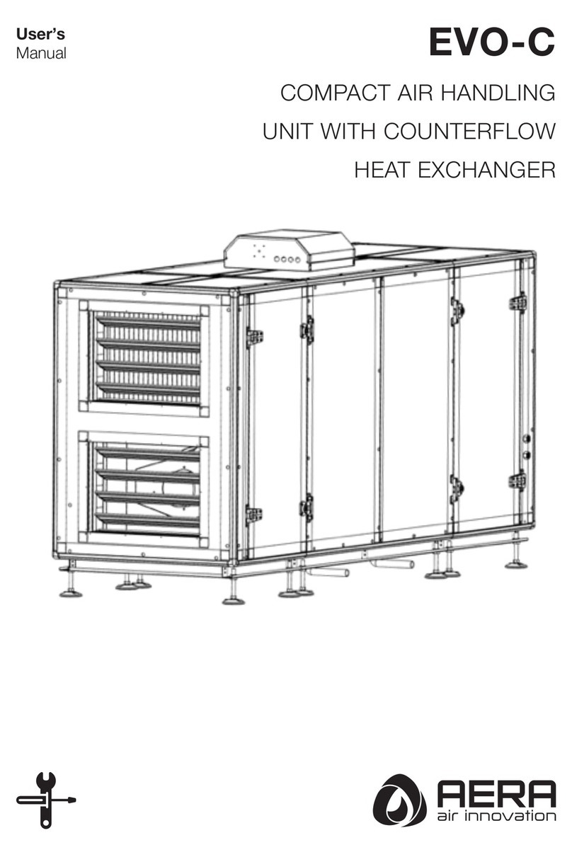
AERA EVO-R User manual

User’s
Manual EVO-R
COMPACT AIR HANDLING
UNIT WITH ROTARY
HEAT RECOVERY

2
Table of Contents
CHAPTER 1 GENERAL INSTALLATION AND OPERATING INSTRIUCTIONS
1.0 Important information………………………………………………………………………………………………………….……Page 4
1.1 Warning and safety instructions………………………………………………………………………...…………………………Page 4
1.2 Warranty claims – Exclusion of liability…………………………………………………………………...………………………Page 4
1.3 Regulations – Guidelines…………………………………………………………………...……………………………………...Page 5
1.4 Receipt…………………………………………………...…………………………………………………………………………..Page 5
1.5 Storage………………………………………………………………………………………………………………..………….….Page 5
1.6 Transport…..……………………………………………………………………………………………………………..……….…Page 5
1.7 Intended use..…………………………………………………………..…………………………………………………………...Page 6
1.8 Performance data…………………………………………………………………………………………………………………...Page 7
1.9 Guideline series VDI 6022….………………………………………………………………………………………..…………….Page 7
1.10 Heat systems….……………………………………………………………………….…………………………………………..Page 7
1.11 Technical data……………………………………………………………………..………………………………………………Page 7
CHAPTER 2 INSTALLATION
2.0 Assembly…………………..……………………………………………………………………………………………....….….....Page 9
2.1 Unit insulation………………………………………………………………………………………………………………………Page 10
2.2 Installation………………………………………………………………………………………………………………………….Page 10
2.3 Flange connection / adapter pieces. ……………………………………………………………………………………………Page 10
2.4 Air ducting, Ventilation circuit…………………………………………………………………………………………………….Page 12
2.5 Electrical Connection…………………………………………………………………………………………………………...…Page 12
CHAPTER 3 FUNCTIONAL DESCRIPTION
3.0 Unit overview…..…………………………………………………………………………………………………….….…………Page 13
CHAPTER 4 DIMENSIONS – PERFORMANCE CURVE
4.0 Dimensions…….……………………………………………………………………………………………………..……………Page 16
4.1 Performance curve….……………………………………………………………………………………………….……………Page 18
CHAPTER 5 SERVICE AND MAINTENANCE
5.0 Service and maintenance…………………………………………………………………………………………………………Page 20
5.1 Service and maintenance of rotary heat exchanger…………..….……………………………………………………………Page 20
5.2 Filter change……………………………………………………………………………………………………………………….Page 23
5.3 Service and maintenance of fan…………………..……………………………………………………………………………. Page 24
5.4 Module assembly…..……………..……………………………………………………………………………………………….Page 26
5.5 Terminal box with isolator/main switch………………………………………………………………………………………….Page 26
CHAPTER 6 Installation, service and maintenance of accessories
6.1 Accessory list………………………………………………………………………………………………………………………Page 27
6.2 Installation of accessories………………………………………………………………………………………………………...Page 34
6.2.1 Installation of electrical after heater……………………….……………………………………………….……….…………Page 34
6.2.2 Installation of outdoor air filter ePM10 50%……………………………..……………………………………………...……Page 35
6.2.3 Installation of recirculation damper...……………………………………………………………………..…………………..Page 36
6.2.4 Installation of outdoor damper…………………………………………………………………………………………………Page 37
6.2.5 Installation of condensate pump………………………………………………………………………………………………Page 39
6.2.6 Installation of water after heater ...……………………………………………………………………………………………...Page -
Page 4
Page 4
Page 4
Page 5
Page 5
Page 5
Page 5
Page 6
Page 7
Page 7
Page 7
Page 7
Page 9
Page 10
Page 10
Page 10
Page 11
Page 11
Page 12
Page 14
Page 18
Page 19
Page 19
Page 21
Page 22
Page 24
Page 25
Page 26
Page 27
Page 27
Page 28
Page 29
Page 30
Page 32
Page 32

3
CHAPTER 7 WIRING DIAGRAM OVERVIEW
7.1 EVO-15R Wiring Diagrams………………………………………………………………………………………………………
7.2 EVO-20R Wiring Diagrams………………………………………………………………………………………………………
7.3 EVO-30R Wiring Diagrams………………………………………………………………………………………………………
7.4 EVO-50R Wiring Diagrams………………………………………………………………………………………………………
7.5 EVO-60R Wiring Diagrams………………………………………………………………………………………………………
7.6 EVO-80R Wiring Diagrams………………………………………………………………………………………………………
7.7 EVO-95R Wiring Diagrams………………………………………………………………………………………………………
7.8 EVO-120R Wiring Diagrams………………………………………………………………………………………………………
7.9 EVO-150R Wiring Diagrams………………………………………………………………………………………………………
CHAPTER 8 SPARE PART LIST
8.1 Spare part list……………………………………………..………………………………….…………………………..………Page 41
Page 33
Page 37
Page 41
Page 45
Page 49
Page 53
Page 57
Page 61
Page 65
Page 69

4
CHAPTER 1
GENERAL INSTALLATION AND OPERATING INSTRIUCTIONS
1.0 Important information
To ensure safety and correct operation please read and observe the following instructions carefully before proceeding.
Important information is specified in the maintenance section on filter changes and necessary cleaning and maintenance
activities. The user usually carries out maintenance work. The chapter “Installation” with important installation
tips and basic unit adjustments is intended for the specialised installer.
The electrical connection must be fully isolated from the supply up to the final assembly!
This appliance is not intended for use by persons (including children) with reduced physical, sensory or mental capabilities,
or lack of experience and knowledge, unless they have been given supervision or instruction concerning use of the appliance by
a person responsible for their safety.
Children should be supervised to ensure that they do not play with the appliance.
The planning office provides the planning documents necessary for system calculations. Additional information can be
requested ex works. Keep the installation and operating instructions as a reference at the device. After the final assembly,
the document must be handed out to the operator (tenant/owner).
1.1 Warning and safety instructions
The adjacent symbol is a safety-relevant prominent warning symbol. All safety regulations and/or symbols must
be absolutely adhered to, so that any dangerous situation is avoided.
1.2 Warranty claims – Exclusion of liability
This device is designed to operate efficiently and safely in the event that they are installed in accordance with the instructions in
the operating instructions, and the operating and maintenance requirements are fully. All maintenance procedures required for
the device must be carried out by experts and authorized persons.
Warranty Conditions
- The devices are warranted against defects in material and workmanship for two (2) years.
- During the warranty period of the device, due to material and manufacturing mistakes in the event of a malfunction, the following
conditions will not be charged;
a. Labor costs
b. Change value of the parts
- The user should report within 8 days of production defects or defects, in terms of the validity of the warranty, immediately upon
the detection of defects, device will be stopped
- As explained in the instruction for use and maintenance, the warranty is valid as long as the devices are periodically maintained.
- Consumables that are periodically changed during the warranty period must be originally supplied from AERA.
- Warranty does not apply to consumables, eg filters.
Issues to be Considered by Customers Related to Warranty
The AERA service personnel or the services authorized by AERA should intervene for the devices covered by the warranty.
Damage caused by installation mistakes or by unauthorized persons is not covered by the warranty.
The following conditions are not covered by warranty:
- Damage due to transportation and improper placement.
- Damage caused by operating the device outside the operating conditions.
- Damage caused by the use of spare parts not approved by the manufacturer.
- Damage due to improper electrical connections, connection other than that specified on the electrical diagram label.
- Damage and failures due to factors such as impact, breaking, scratching and freezing.

5
- Faults that may arise from irregularities in the electrical supply where the device is installed.
- Damage caused by failure to make drainage pipe and to be corrosion inside the device.
- Damage that may be caused by the corrosive and acidic effect of the environment in which the device will operate.
- Damages caused by foreign materials forgotten in the device or fan motor.
- Damage caused by not using flexible connection in channel connections.
- Damages caused by failure to observe the points specified in this user manual.
AERA heat recovery devices do not have any parts replacement or repair work to be performed by the user other than cleaning
and eye inspection. Users should contact the AERA company for faults detected during operation or maintenance.
1.3 Regulations – Guidelines
If the product is installed correctly and used to its intended purpose, it conforms to all applicable CE standards at its date of
manufacture. The AERA EVO-R ventilation units in this series are compliant with Eco-Design 2018.
1.4 Receipt
The delivery contains one of the following unit types:
Please check delivery immediately on receipt for accuracy and damage. If damaged, please notify carrier immediately.
In case of delayed notification, any possible claim may be void.
1.5 Storage
When storing for a prolonged time the following steps are to be taken to avoid damaging influences:
Protection by dry, air- dustproof packing (plastic bags with drying agent and moisture indicators). The storage place must be
water-protected, vibration-free and free of temperature variations. (Ambient temperature limit, min/max, 0°C/ +40°C) Damages
due to improper transportation, storage or putting into operation are not covered by warranty.
1.6 Transport
The transport of the devices must be done with carefully. All manufactured devices are shipped from the factory after all tests and
controls have been made before shipment.
The transport must be carried out by trained and experienced personnel and the necessary safety precautions should be taken
to prevent overturning and slipping of the device. During transport of the devices it should be ensured that the weight is evenly
distributed over the four corners.
Danger due to overhead loads – risk of grave injuries or death!
- Never stand beneath suspended loads, since there is always a risk that the lifting gear, tackle, ropes or slings are faulty or
damaged.
Unit
EVO-15R
EVO-20R
EVO-30R
EVO-50R
EVO-60R
EVO-80R
EVO-95R
EVO-120R
EVO-150R
Unit
EVO-15R/SO
EVO-20R/SO
EVO-30R/SO
EVO-50R/SO
EVO-60R/SO
EVO-80R/SO
EVO-95R/SO
EVO-120R/SO
EVO-150R/SO

6
- Make sure that equipment is firmly seated before lifting it.
Warning! Risk of personal injury and equipment damage!
Due to a high center of gravity, some equipment can tend to tip over and cause damage to persons and property.
- When transporting the unit, carefully observe its behavior and do not get near any possible hazardous areas.
1.7 Intended use
EVO-R devices are designed in 9 different models to correspond the need of up to 15000 m3/ h air flow. There is an ePM1 55%
class filter on the outdoor air side and an ePM10 50% class filter on the exhaust side as standard. The units are produced
according to European Union energy criteria and have EcoDesign label.
EVO-R devices are designed with energy efficient, low sound pressure radiating and low power consumption plug fans. Plug fans
with EC motors can be driven with 3 fixed speeds or steplessly with the help of an air quality sensor thanks to build in smart control
system.
The EVO-R units are equipped with rotary heat exchanger. More than 80 % of the extract air heat is transferred to the outdoor air.
The supply air is led by the duct system to the primary (supply air needing) areas. The used air is extracted from the secondary
areas (like e.g. social rooms, toilets, showers etc.). It flows back through the ducting to the ventilation unit, transfers the heat and
is discharged by the exhaust air duct to the atmosphere.
The heat recovery efficiency depends on several factors, which include, among other things, air humidity and the temperature
variation of outside air and exhaust air. The fan performance can be adjusted by the controller in scope of delivery. Various
sensors e.g. CO2 or humidity sensors (accessory) are available on request, with which automatic fan control is possible
If the device is used at < + 5 °C, it is necessary to use a heater in the device electronic box. (not included scope of delivery,
optional)
The standard equipment permits the installation and the application in frost-free rooms > + 5 °C.
If the unit is to be used in outdoor, it is necessary to use a weather roof and outdoor spigot. (not included scope of delivery,
optional)
If the unit is to be used in other applications where high humidity, excessive dust, temperature in excess of 40 °C or long periods
at standstill (not running), please contact AERA sales representative. This also applies for special technical and electrical
applications.
The EVO-R units are equipped with an electrical pre-heater (accessory- not included in scope of delivery); this prevents the heat
exchanger from freezing at extremely cold outdoor temperatures.
Electrical after heater (accessory) used in EVO-R devices can be installed in the unit (EVO-15R, EVO-20R, EVO-30R) and module
(EVO-50R, EVO-60R, EVO-80R, EVO-95R, EVO-120, EVO-150R). The after heater is controlled by the desired supply air
temperature. The temperature is chosen by the user.
Water after heater (accessory) are used for increasing the supply air temperature and for bringing the supply air to the desired
temperature. Hot water coils can be driven by proportional control via 2 or 3-way valves. Frost protection mechanism is available
as standard to prevent the temperature of the supply water from reaching freezing conditions in extreme cold climates.
Externally module water cooling coils and DX coils (accessory) are used for such purposes as lowering the blowing temperature
and dehumidifying the air in the units. It can be driven either proportionally or by on / off method.

7
1.8 Performance data
Mechanical connections must be made correctly in order to obtain maximum efficiency from the device. The device's thermal
efficiency, sound level and electrical performance may vary depending on the ambient conditions the device is operating. These
conditions may affect the measurement result on site and vary from the catalogue data.
1.9 Guideline series VDI 6022
The AERA EVO-R ventilation units in this series are produced compliant with VDI 6022. The guidelines range from operating
regulations and material requirements through to construction regulations, which ensure high air quality. It must be ensured that
only original AERA accessories are used for operation compliant with VDI 6022.
1.10 Heat systems
The relevant applicable regulations on the combined use of heat systems, domestic ventilation and extractor hoods (Federal
Association of Chimney Sweeps (ZIV) information) must be observed!
General construction-law requirements
The EVO-R units with heat recovery must only be installed and operated in rooms with heat systems which depend on room air,
if their flue gas venting is monitored by specific (on-site) safety devices, which shut down the EVO-R unit when activated. We
recommend speaking with the competent chimney sweep to take account of possible wishes before procuring a negative pressure
monitoring system for heat systems.
1.11 Technical data
MODEL
EVO-R
15
20
30
50
60
80
95
120
150
Air flow (m3/h)
1500
2000
3000
5000
6000
8000
9500
12000
15000
Rated current – ventilation (A)
2,17
3,39
2,28
3,8
3,65
5,47
5,32
7,6
9,12
Max. total rated current (A)
8,3x8,3x7,2
11,8x11,8x9,5
17,7x17,7x18,8
7,6x7,6x8,7
7,3x7,3x8,4
11x11x12,1
10,7x10,7x12,3
15,2x15,2x16,9
18,3x18,3x19,9
Power consumption – ventilation (kW)
0,5
0,78
1,5
2,5
2,4
3,6
3,5
5
6
Max. power consumption (kW)
5,4
7,6
12,3
5,2
5
7,4
7,4
10,4
12,4
Voltage/Frequency
3~400V 50Hz
3~400V 50Hz
3~400V 50Hz
3~400V 50Hz
3~400V 50Hz
3~400V 50Hz
3~400V 50Hz
3~400V 50Hz
3~400V 50Hz
Filter class (extract/ outdoor air)
ePM10 50% -M5 /
ePM1 55% - F7
ePM10 50% -M5 /
ePM1 55% - F7
ePM10 50% -M5 /
ePM1 55% - F7
ePM10 50% -M5 /
ePM1 55% - F7
ePM10 50% -M5 /
ePM1 55% - F7
ePM10 50% -M5 /
ePM1 55% - F7
ePM10 50% -M5 /
ePM1 55% - F7
ePM10 50% -M5 /
ePM1 55% - F7
ePM10 50% -M5 /
ePM1 55% - F7
Weight (kg)
Sound pressure (dB)
56
54
57
53
58
60
59
59
59
Standby losses
IP Class with weather roof
IP54
IP54
IP54
IP54
IP54
IP54
IP54
IP54
IP54
IP Class without weather roof
IP20
IP20
IP20
IP20
IP20
IP20
IP20
IP20
IP20
Wiring diagram
MODEL
EVO-R/SO
15
20
30
50
60
80
95
120
150
Air flow (m3/h)
1500
2000
3000
5000
6000
8000
9500
12000
15000
Rated current – ventilation (A)
2,17
3,39
2,28
3,8
3,65
5,47
5,32
7,6
9,12
Max. total rated current (A)
8,3x8,3x7,2
11,8x11,8x9,5
17,7x17,7x18,8
7,6x7,6x9,3
7,3x7,3x9
11x11x13,8
10,7x10,7x13,4
15,2x15,2x18
18,3x18,3x21
Power consumption – ventilation
(kW)
0,5
0,78
1,5
2,5
2,4
3,6
3,5
5
6
Max. power consumption (kW)
5,4
7,6
12,3
5,2
5
7,4
7,4
10,4
12,4
Voltage/Frequency
3~400V 50Hz
3~400V 50Hz
3~400V 50Hz
3~400V 50Hz
3~400V 50Hz
3~400V 50Hz
3~400V 50Hz
3~400V 50Hz
3~400V 50Hz
Filter class (extract/ outdoor air)
ePM10 50% -M5 /
ePM1 55% - F7
ePM10 50% -M5 /
ePM1 55% - F7
ePM10 50% -M5 /
ePM1 55% - F7
ePM10 50% -M5 /
ePM1 55% - F7
ePM10 50% -M5 /
ePM1 55% - F7
ePM10 50% -M5 /
ePM1 55% - F7
ePM10 50% -M5 /
ePM1 55% - F7
ePM10 50% -M5 / ePM1
55% - F7
ePM10 50% -M5 / ePM1
55% - F7
Weight (kg)
Sound pressure (dB)
56
54
57
53
58
60
59
59
59
Standby losses
IP Class with weather roof
IP54
IP54
IP54
IP54
IP54
IP54
IP54
IP54
IP54
IP Class without weather roof
IP20
IP20
IP20
IP20
IP20
IP20
IP20
IP20
IP20
Wiring diagram

8
EcoDesign Points
15
20
30
50
60
80
95
120
150
Declared typology
Bidirectional
Bidirectional
Bidirectional
Bidirectional
Bidirectional
Bidirectional
Bidirectional
Bidirectional
Bidirectional
Type of drive
Variable
Variable
Variable
Variable
Variable
Variable
Variable
Variable
Variable
Type of HRS
Recuperative
Recuperative
Recuperative
Recuperative
Recuperative
Recuperative
Recuperative
Recuperative
Recuperative
Nominal NRVU flow rate [ m3/h ]
1400
2200
2900
4400
5500
8000
9500
12500
15000
Thermal efficiency of heat recovery
[ % ]
81
79
79
81
81
81
81
79
82
Static efficiency of fans [ % ]
58,2
61,4
52,8
63,6
63,6
62,4
64,1
67,2
63,5
Effective electric power input [kW ]
0,48
0,77
1,12
2,46
2,34
3,27
3,25
4,88
5,57
Face velocity [ m/s ]
1,4
2,03
1,76
1,71
1,75
1,85
1,89
2,07
1,94
Normal external pressure [ Pa ]
250
250
300
350
350
350
350
350
350
Internal pressure drop of
ventilation components [ Pa ]
274
368
310
274
280
288
298
334
302
SFPint [ W/(m3/s) ]
926
1183
1157
847
867
908
914
976
936
Declared maximum external
leakage [ % ]
<1
<1
<1
<1
<1
<1
<1
<1
<1
Declared maximum internal
leakage [ % ]
<3
<3
<3
<3
<3
<3
<3
<3
<3
Description of visual filter warning
Pressure
controled
Pressure
controled
Pressure
controled
Pressure
controled
Pressure
controled
Pressure
controled
Pressure
controled
Pressure
controled
Pressure
controled
Casing sound power level (Lwa) [
dB(A) ]
ErP Compliance
2018
2018
2018
2018
2018
2018
2018
2018
2018

9
CHAPTER 2
INSTALLATION
2.0 Assembly
EVO-R compact devices must be mounted in a vertical position. Due to noise level which change according to working conditions,
it is recommended to install the EVO-R units in the infrequently used rooms like that storage rooms, washing rooms etc. If the
device to be used has a cooling coil, ensure that there is a waste water connection in the installation area. Assembly should take
place in such a way to enable preferably short ventilation ducts and their trouble-free connection to the unit. Tight bends can lead
to increased pressure loss and flow noise. The unit can be turned 180° for optimal installation, so that the outdoor/exhaust air and
extract/supply air inlets and outlets can be on the left or right side. There is no need for bends and long stretches of pipeline due
to these features. They reduce losses and increase the degree of efficiency of the system.
Important notes:
1. The ventilation ducts must not become kinked.
2. Any kind of connections (valves, flanges etc.) which associated with fluids like that air or water, must be tight and leakproof.
3. If necessary, vibration isolators can be used between unit and floor.
4. In order to prevents sound transmission, appropriate acoustic decoupling must be provided on site depending on the building
material.
The outdoor spigot should be placed on the exhaust air side in case of no duct connection.
Make sure that the device is placed on a flat surface before any assembly work.
Assembly area
Observe the following criteria during installation to ensure that the device service is comfortable. (Fig. 1)
A is the minimum distance for servicing the terminal box.
C is the minimum distance for opening service cover.
MODEL
A (mm)
B (mm)
C (mm)
D (mm)
EVO-15R
600
910
1360
1145
EVO-20R
600
1010
1460
1245
EVO-30R
600
1120
1570
1355
EVO-50R
600
1390
1840
1625
EVO-60R
600
1510
1960
1745
EVO-80R
600
1760
-
1995
EVO-95R
600
1860
2310
2095
EVO-120R
600
2010
2460
2245
EVO-150R
600
2260
2710
2495
Fig. 1

10
2.1 Unit insulation
The outside and exhaust air ductwork should be insulated sufficiently.
If the unit is to be used in outdoor, make sure that the necessary equipment is installed. (weather roof and outdoor spigot, optional)
2.2 Installation
EVO-R has easily adjustable stays. (Fig. 2) First of all, make sure that there is enough space for the device servicing. Therefore,
the device must be assembled after the dimensions have been identified.
Make sure that the device is placed on a flat surface before any assembly work.
2.3 Flange connection / adapter pieces
EVO-R flange connection diameters are shown below (Fig.3)
Fig. 2
Fig. 3

11
Model
Dimensions (mm)
A
B
C
n
D
m
E
F
K
L
EVO-15R
350
310
14,14
0
-
0
-
-
378,28
338,28
EVO-20R
470
310
14,14
0
-
0
-
-
498,28
338,28
EVO-30R
580
410
14,14
1
304,1
0
-
30
608,28
438,28
EVO-50R
855
410
14,14
1
441,6
0
-
30
883,28
438,28
EVO-60R
855
410
14,14
1
441,6
0
-
30
883,28
438,28
EVO-80R
1055
410
14,14
2
361,1
0
-
30
1083,28
438,28
EVO-95R
1200
410
14,14
2
409,4
0
-
30
1228,28
438,28
EVO-120R
1475
510
14,14
2
501,1
1
269,1
30
1503,28
538,28
EVO-150R
1600
710
14,14
3
407,1
1
369,1
30
1628,28
738,28
n : number of drill hole (horizontal) (Except corner holes)
m : number of drill hole (vertical) (Except corner holes)
Hole/Bolt dimension : M8X20
2.5 Air ducting, Ventilation circuit
When designing the ductwork, use the shortest possible runs. Airtight connections and changeovers must be ensured for the best
possible heat recovery. To avoid pressure losses, dirt build-up and noise, use smooth ducts (plastic or rigid ducting). If supply and
extract air ductworks run through unheated rooms, insulation must be provided to reduce heat losses. Fresh air should be supplied
to living and bedrooms and extraction should take place in bathrooms, toilets and kitchens. The installation of extractor hoods to
the system is not permitted (reasons: dirt, fire danger, hygiene).
All fire and building regulations must be observed!
2.6 Electrical Connection
The unit must be fully isolated from the mains power supply before any maintenance and
installation work or before opening the enclosure! The electrical connection must only be carried out by an authorised
qualified electrician in accordance with the following wiring diagrams. The electrical connection must be fully isolated
from the mains power supply until the assembly is complete!
The unit is equipped with a main switch and an isolator which can be secured against unauthorized switching with a U-lock. The
relevant standards, safety regulations (e.g. DIN VDE 0100) and the technical connection conditions of the local electricity supply
companies must be observed. An all-pole mains switch / isolator, with a contact opening of at least 3 mm (VDE 0700 T1 7.12.2 /
EN 60335-1) must be provided. The main switch and/or isolator can be secured against unauthorized switching with a U-lock.
The surface-mounted controller with touchscreen is connected to the unit by means of a 5 m connecting cable (also available in
10 or 20 m length). The electrical connection of the EVO-R takes place directly in the terminal box. If any electronic accessory is
added the unit, the electrical connections must be made in the terminal box.

12
CHAPTER 3
FUNCTIONAL DESCRIPTION
3.0 Unit overview
-Non-dividable unit (EVO-15R, EVO-20R, EVO-30R) (Fig. 4)
1
10
4
5
8
8
2
7
9
6
3
11
1. Terminal box
2. Exhaust air fan
3. Supply air fan
4. Outdoor air pre-filter (ePM10 50%) (optional)
5. Extract air filter (ePM10 50%)
6. Outdoor air main filter (ePM1 55%)
7. Rotary heat exchanger
8. Outdoor damper (optional)
9. Water heater coil or electrical after heater (optional)
10. Main switch
11. Casing
Fig. 4

13
-Dividable unit (EVO-50R, EVO-60R, EVO-80R, EVO-95R, EVO-120R, EVO-150R) (Fig. 5)
1. Terminal box
2. Exhaust air fan
3. Supply air fan
4. Outdoor air pre-filter (ePM10 50%) (optional)
5. Extract air filter (ePM10 50%)
6. Outdoor air main filter (ePM1 55%)
7. Rotary heat exchanger
8. Outdoor damper (optional)
9. Recirculation damper (optional)
10. Main switch
11. Casing
8
10
1
6
2
8
7
4
5
9
3
11
Fig. 5

14
CHAPTER 4
DIMENSIONS
PERFORMANCE CURVE
4.0 Dimensions
-Non-dividable unit (EVO-15R, EVO-20R, EVO-30R) (Fig. 6)
MODEL
A
B
C
D
E
F
K
L
M
N
X
Y
Dimensions (mm) (Fig. 6)
EVO-15R
1295
990
155
1700
760
910
205
360
415
520
350
310
EVO-20R
1400
1090
155
1700
860
1010
205
360
415
520
470
310
EVO-30R
1500
1200
155
1700
970
1120
205
360
415
520
580
410
Fig. 6

15
MODEL
AA
BB
CC
DD
EE
FF
GG
HH
Dimensions (mm) (Fig. 7)
EVO 15-R
680
568
472
93,5
150
463,2
263,4
380
EVO 20-R
670
568
472
143,5
150
514,2
286,4
430
EVO 30-R
680
568
472
193,5
150
573,2
313,4
485
Fig.7

16
-Dividable unit (EVO-50R, EVO-60R, EVO-80R, EVO-95R, EVO-120R, EVO-150R) (Fig. 8)
MODEL
A
B
C
D
E
F
K
M
P
R
S
X
Y
Dimensions (mm)
EVO-50R
1775
1470
155
1845
1240
1390
610
1230
555
440
690
855
410
EVO-60R
1895
1590
155
2015
1360
1510
680
1330
625
480
748
855
410
EVO-80R
2145
1840
155
2100
1610
1760
750
1350
-
-
-
1055
410
EVO-95R
2245
1940
155
2315
1710
1860
830
1480
775
605
775
1200
410
EVO-120R
2400
2090
155
2450
1860
2010
895
1550
840
605
845
1475
510
EVO-150R
2645
2340
155
2535
2110
2260
940
1590
890
620
870
1600
710
Fig. 8

17
MODEL
AA
BB
CC
DD
EE
FF
GG
HH
JJ
KK
LL
MM
Dimensions (mm) (Fig. 9)
EVO 50-R
150
45
568
615
472
366,5
620
725
372,5
59,6
130,4
106
EVO 60-R
150
125
568
690
472
446,5
680
785
402,5
179,6
130,4
106
EVO 80-R
150
---
568
---
472
---
805
---
---
429,6
130,4
106
EVO 95-R
150
125
568
840
472
616,5
855
960
490,5
529,6
130,4
106
EVO 120-R
150
125
568
910
472
696,5
930
1035
527,5
679,6
130,4
106
EVO 150-R
150
125
568
950
472
816,5
1055
1160
589,5
929,6
130,4
106
Fig. 9

18
4.1 Performance curve

19
CHAPTER 5
SERVICE AND MAINTENANCE
5.0 Service and maintenance
The filter change is usually carried out by the user. Additional cleaning and maintenance work must only be carried out
by qualified electricians.
The EVO-R unit must be fully isolated from the power supply and secured against reactivation with the main
isolator switch located on top of the unit before any cleaning and maintenance work.
Danger of electric shock, moving parts (fan) and hot surfaces.
5.1 Service and maintenance of rotary heat exchanger
Make sure that the power connection is disconnected before doing any work on the device. Danger of electric
shock; moving parts (fan) and hot surfaces.
Maintenance is restricted to regular visual inspections. Inspections should be initially carried out about every 3 months and then
after trouble-free operation can be extended to 12 months. The following must be checked:
- Tension of drive belt
- Quality of bearings (assess by bearing noise)
- Function of slide seal
- Condition of casing
RISK OF INJURY! High weight! Two people are required for dismantling! (EVO-15R, EVO-20R)
Use forklift to transport the heat exchanger on the EVO-30R, EVO-50R, EVO-60R, EVO-80R, EVO-95R, EVO-120R,
EVO-150R models
1. Unscrew the screws of the device service cover and open (Fig. 10)
Unit
Rotary heat
exchanger weight
(kg)
EVO-15R
38
EVO-20R
45
EVO-30R
51
EVO-50R
76
EVO-60R
104
EVO-80R
136
EVO-95R
152
EVO-120R
177
EVO-150R
218
Fig. 10

20
2. Remove the exhaust fan to disconnected the electrical connections easily. (6.3 Service and maintenance of the fan)
3. Unplug the electrical connections on the varimax drive unit (Fig. 11)
3. Pull lock-bars for unlock heat exchanger (Fig. 12)
4. Pull the heat exchanger to remove (Fig. 13)
Fig. 11
Fig. 12
Fig. 13
Table of contents
Other AERA Air Handler manuals
Popular Air Handler manuals by other brands

McQuay
McQuay IM 777-3 Installation and maintenance manual

Kampmann
Kampmann KaCool HY 600x600 Installation, operation & maintenance manual
Verano
Verano freshAIR+ VWT Installer manual

Lennox
Lennox LGH Series Unit information

Hoval
Hoval RoofVent RH Series Original operating manual
Trane
Trane BAYWACC11SC1AA Installer's guide

Armstrong Air
Armstrong Air BCE3M 18 installation instructions

Frico
Frico PA2500 Original instructions
Magic Aire
Magic Aire HCA Series Installation, operation and maintenance manual
Armstrong Air
Armstrong Air BCE7E Series installation instructions
TemperZone
TemperZone IJD 2000 Installation & maintenance
Dantherm
Dantherm VA-M40 MKII Service manual

