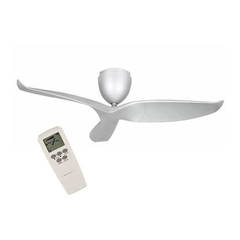
AerAtron AE+2 Series User manual

INSTRUCTION MANUAL
AE+2 & AE+3

ATTENTION ELECTRICIANS
Available in: 43”/1092mm 50”/1270mm 60”/1524mm
LED Light Kit & Ceiling Extension Kit are oponal for all Aeratron™ models
AE+2 & AE+3 CEILING FAN
An isolaon switch per fan is highly recommended.
WARNING: If unusual oscillang movement is observed, immediately
stop using the ceiling fan and contact the naonal distributer/retailer.
USER MANUAL & INSTALLATION GUIDE
For Metal Hanger Bracket with Safety Cord
Check Fan Suspension system regularly, at least once every two years.

Important information - Please read before attempting installation
1
!
This fan must be installed by a licensed and qualified
electrician according to local authority regulaons.
1. Please read these instrucons carefully, be mindful of all warnings and safety informaon shown
throughout this manual. Should you have any quesons please call your local agent.
2. Please review the accompanying assembly diagrams before aempng installaon.
3. This fan MUST be installed by a licensed & qualified electrician according to local authority
regulaons and in accordance with current wiring rules of the country/state.
4. A copy of the purchasing receipt and proof of installaon by a licensed and qualified electrician
according to local authority regulaons is required for all warranty claims.
5. Where special access equipment is required to service the fan in accordance with local authority
regulaons all associated costs are the responsibility of the owner.
6. Should a warranty claim be required, we reserve the right to charge a service fee for all call outs
where the fan is found not to be defecve and / or where access is not provided.
7. To enable future programming, maintenance, cleaning and troubleshoong an isolaon switch per
fan is highly recommended. Without an isolaon switch per fan, an electrician maybe required to
assist with programming, maintenance, cleaning and troubleshoong. All associated costs are the
responsibility of the owner.
8. A Maximum of 8 fans on each RCD / circuit is recommended. The fans are a Class 5 Device with
leakage to Earth.
9. Your warranty will be void if a solid state dimmer or any other brand of wall controller is used.
10. The means for mains power disconnecon must be incorporated in the fixed wiring in accordance
with naonal wiring rules.
11. To avoid possible electric shock during installaon, be sure electricity is turned off at the main power
box before commencing work. Disconnect power by removing fuse or turning off circuit breaker
before installing the fan. Ensure all spliced connecons are adequately insulated.
12. Warning! Do not allow the rotang fan blades to come into contact with any object, this can cause
serious injury or death.
13. Damage caused by incorrect installaon, Force-majeure, lightning, electrical surges & spikes,
exposure to water, pests or moisture is not covered under warranty.
14. This appliance is not intended for use by persons (including children) with reduced physical, sensory
or mental capabilies, or lack of experience and knowledge, unless they have been given supervision
or instrucon concerning use of the appliance by a person responsible for their safety.
15. Suspension System
· the replacement of parts of the safety suspension system device shall be performed by the
manufacturer, its service agent, or suitably qualified persons.
· fixing means for aachment to the ceiling such as hooks, or other devices shall be fixed with a
sufficient strength to withstand 4 mes the weight of the ceiling fan.
· the mounng of the suspension system shall be performed by the manufacturer, its service agent,
or suitably qualified persons
· the model or type reference of a luminaire that may be installed in a fan must be constructed for
this purpose
Australia, New Zealand: In accordance with AS/NZS60355-1 & ASNZS60355-2-80: “This appliance is
not intended for use by persons (including children) with reduced physical, sensory or mental
capabilies, or lack of experience and knowledge, unless they have been given supervision or
instrucon concerning use of the appliance by a person responsible for their safety. Children should
be supervised to ensure that they do not play with the appliance.”

Contents
2
IMPORTANT
assistance before leaving the site.
Important Informaon ................................................................................................................ 1
Contents ...................................................................................................................................... 2
Unpacking your fan ..................................................................................................................... 3
Installing your Fan ....................................................................................................................... 4
STEP1 Mounng the Hanger Bracket to Ceiling....................................................................... 4
STEP 2 Connecng Mains Power to Terminal Block.................................................................4
STEP 3 Inserng Fan Motor into Hanger Bracket..................................................................... 5
STEP 4 Installing Receiver into Hanger Bracket ....................................................................... 5
STEP 5 Connecng Receiver..................................................................................................... 6
STEP 6 Pairing the Remote Control .........................................................................................7
STEP 7 Aaching the Fan Motor Housing ................................................................................ 8
STEP 8 Assembling the Fan Blades........................................................................................ 8,9
STEP 9 Aaching the Fan Blades ............................................................................................. 9
Opon A - LED Light Kit .............................................................................................................10
Opon B - Ceiling Extension Kit................................................................................................. 10
Opon C - Raked Ceiling Kit....................................................................................................... 11
Technical Specificaon .............................................................................................................. 12
Care and Cleaning ..................................................................................................................... 13
Troubleshoong ........................................................................................................................ 13
If the fan is noisy .................................................................................................................... 13
If the fan rotates but does not create much airflow.............................................................. 13
General Informaon.................................................................................................................. 14
Normal Wear and Tear .......................................................................................................... 14
Warranty details........................................................................................................................ 15

3
Unpacking your fan
Unpack your fan and examine all parts, you should have the following:
CONTROL RECEIVER
MOTOR HOUSING
AE+3 HUB UPPER
AE+3 HUB LOWER
AE+2 HUB UPPER
AE+2 HUB LOWER
FAN BLADE: AE+2 x 2
AE+3 x 3
CEILING SPACER x 2
OR
OR
METAL HANGER BRACKET
MOTOR ASSEMBLY
SAFETY CORD
TIMBER SCREWS X 5
PIVOT LOCK X1
HUB SCREWS X 10
EXPANSION BOLT X 4
HOOK BOLT X 1
REMOTE CONTROL
AAA BATTERIES x2
NOTE: Wall control / automaon control & wifi module components are not included;
please contact your local fan supplier for more informaon.

STEP 1 Mounting Metal Hanger Bracket to Ceiling
supply at the main power box. Disconnect power
by removing fuse or turning off circuit breaker.
!
STEP 2 Connecting Mains Power to Terminal Block
4
Install hanger bracket to ceiling joist or concrete ceiling using a minimum of (4) bolts/ screws as provided. Ensure
ceiling joists are sound and of adequate size and strength to support a 32Kg (70lbs) load. If a mber frame is to be
added it must be securely nailed or screwed between two beams. Mount the hook bolt / mber screws for the
safety cable within the motor housing opening, approx Ø165mm from the centre of the hanger bracket.
WARNING: MOUNT ONLY TO AN OUTLET BOX MARKED ACCEPTABLE FOR FAN SUPPORT.
This fan is to be installed so that the blades are more than 2.3m above the floor
OPTION A:
Ceiling Joist
OPTION B:
Concrete Ceiling
Ø165mm
Hook bolt or
mber screw
Expansion bolt or
mber screw
4 mber screws 4 expansion bolts
N
L
CONNECT WITH RECEIVER
3PIN
NEUTRAL
LIVE
L
LIVE
LIVE
GROUND
GREEN
BROWN L
BLUE N
FROM HOUSE
(Mains Power)

Inserting an otor into Hanger Bracket and
=
STEP 4 Installing Receiver into Hanger Bracket
5
STEP 3
Wooden Ceiling (use Timber Screws)
Concrete Ceiling (use Expansion Bolts)
Secure Safety Cord Loop
with Timber Screw
Secure Safety Cord
Loop with Hook Bolt
Locate Suspension Ball in Hanger Bracket and secure the (loop) of the Safety cord to the
hook expansion bolt or secure the Safety cord loop to the Ceiling with the Timber Screw.
Ensure the safety cord is not stretched otherwise it will hinder the receiver sliding
through the hanger bracket.
Secure Safety Cord
Slide Remote Control Receiver
into Hanger Bracket from the
opposite side of the Terminal block
in the orientaon as shown below.
Oponal
Wifi module
Antenna

6
Connecting the Receiver
STEP 5
X0
Learn Switch
Switch to “O” to pair receiver
with the Remote control and
Switch to “X” to lock the pairing
code with the Remote control
2PIN LED driver connection
(optional for LED light)
3PIN
3PIN
Mains Power
Aerial
4PIN Comms
Connector
(Optional USE ONLY
IF INSTRUCTED)
1.
2.
Connect the 3PIN connector (Mains Power)
between Hanger Bracket and Reciever.
Connect the3PIN
& Earth cable connector
between DC Motor and Receiver.
3PIN
Receiver to
Hanger bracket
3PIN
Receiver
to Motor
Earth Cable

The remote control is pre-programmed
No pairing with the receiver required
STEP 6 Pairing the Remote Control
Controlling the Fan
1. Fan ON/OFF
2. Fan Speed UP/DOWN
2a. Fan Speed indicator 1-6
3. Forward / Reverse
3a. Use Forward mode (counterclockwise) for cooling
3b. Use Reverse mode (clockwise)
to circulate warm air
4. Light ON/OFF
4a. To DIM, press and HOLD light buon
to cycle from bright to dark.
(LIGHT SWITCH at DIMMING posion)
Pairing Mulple Fans per Remote Control
One remote control can control up to 8 fans (within a 7m (23”) radius).On ALL receivers verify that
the “Learn” switch is in the “O” posion. Switch on the mains power to acvate ALL receivers at the
same me, indicated by one ‘beep’. Within 60 seconds, press and hold the ON/OFF buon on the
remote control (min. 3 seconds) unl fan receiver issues three ‘beeps’.
!
1
4
3b
2
2a
3
3a
4a
LIGHT SWITCH
O LIGHT DIMMING
| LIGHT ON/OFF
Pairing a Single Fan per remote control: LEARN MODE
NOTE: Blades must be aached prior to tesng the fan
1. On Receiver: Verify that the “Learn” switch is in the “O” posion
2. Open baery cover & insert baeries.
3. Switch on the main power to acvate the receiver, indicated
by one beep. (Energise one fan reciever at a me).
4. Within 60 seconds aer the power is turned on (one beep),
press and hold the ON/OFF buon on the Remote Control
(min. 3 secs.) unl Fan Receiver issues three ‘beeps’ which
indicates successful pairing.
5. On Receiver: switch the “Learn” switch to “X” (this will
lock the pairing code with the remote)
6. Finish STEP 7, 8 & 9 and press ON/SPEED buon to test
fan funcons.
7. To re-pair, repeat steps 3 to 5
NOTE: Power must be off for 10 seconds min. before repairing.
The Remote Control and Fan Receiver will memorise the pairing
code for future use even if mains power is switched off.
LIGHT SWITCH: Select ON/OFF or DIMMING for the light funcon.
(Light will maintain last seng if turned off)
7

8
STEP 7 Attaching the Fan Motor Housing
Align the 3 tabs with the 3 holes on the
Housing and move upwards. Push tabs
inwards slightly before sliding upwards
unl you hear a click as the tabs lock.
STEP 8 Assembling the Fan Blades
A B
Place the Hub Upper onto a clean working area.
Line-up the two mounng holes in the Fan Blade
with the 2 holes in the Hub Upper. To ensure ght and secure blade assembly a
power tool on low torque seng (4-6) can
be used.
Fix the 3 Fan Blades ght and firm using 2 Hub
screws for each Blade.
Connues next page
CLICK!
Constantly handle fan with care at all mes to
avoid damaging the fan/surface
!

C
Lock Screw
9
STEP 9 Attaching the Fan Blades
44
STEP 8 Assembling the Fan Blades cont.
C D
Insert the Hub Lower (or oponal Light Hub
Lower) into the recess. With care, turn the fan
over.
Fasten the the Hub Lower from the top side
using the 3 Hub Screws.
No liability is accepted if the Silicone ring is
removed or the Pivot Lock is installed
incorrectly/lock screw is not ghtened.
Ensure fan sha is vercal.
The fan will be vercal if
the clearance ‘X’ between
the ceiling and motor
housing is equal all way
round.
!
Align Drive Sha with Pivot
Connector and slide fan
blades onto Drive Sha.
Hold/push up Fan Blades
and insert Pivot Lock,
defelecng the silicon
sideways. Push Pivot Lock
into the sha.
Tighten Lock Screw
securely using screw driver.
Do not use power tools.
D
x
A
Drive Sha
Pivot Connector
Silicone Ring
B
Pivot Lock
Silicone Ring
Light Hub Lower
(OPTIONAL)

10
44
OPTION A LED Light Kit
Line up the 2 pins on the LED light with the 2 Holes in the
Ceramic Holder and gently push the LED Light up ll the
Safety clip is engaged.
Re-check the correct assembly by gently pulling on the
Light to make sure the LED is ght.
OPTION B Ceiling Extension Kit
“A”
150mm (6”)
“B”
26.6mm ROD
Suitable for Raked Ceiling up to 17
LED LIGHT
“B” Extension Rod Length
115mm Rod (4 17/32”)
600mm Rod (23 5/8”)
900mm Rod (35 7/16”)
Accessories Required
Included
Not Included
Not Included
“A” Ceiling to Fan blade
420mm (16 17/32”)
910mm (35 53/64”)
1210mm (47 41/64”)

11
OPTION C Raked Ceiling Kit
CEILING JOIST
“B”
“C”
“a”
“B” Extension Rod Length
115mm Rod (4 17/32”)
600mm Rod (23 5/8”)
900mm Rod (35 7/16”)
Accessories Required
Included
Not Included
Not Included
“C” Clearance
200mm min.
“a” Angle
17° - 33°

12
Technical Specifications
43” 1092mm / 50” 1260mm / 60” 1524mm
Dimensions for Model:
AE+2 43” & AE+3 43”
AE+2 50” & AE+3 50”
AE+2 60” & AE+3 60”
Fan Weight:
AE+2 43” = 4.9Kg (10.8lbs)
AE+3 43” = 5.5Kg (12.1lbs)
AE+2 50” = 5.1Kg (112lbs)
AE+3 50” = 5.7Kg (12.7lbs)
AE+2 60” = 5.6Kg (12.3lbs)
AE+3 60” = 6.5Kg (14.3lbs)
Colour Opons:
White/Silver/Black
Dark/Light wood-grain
Remote Control:
Hand held, RF
Standby power 0.49W
Opons:
Wall switch control
Automaon control
Wifi control module
180mm (7”) 275mm 10 (53/64”)
172mm (6 49/64”)

13
Care and Cleaning
Troubleshooting
Regular cleaning of the Aeratron Ceiling fan blades and fan motor housing is the only maintenance needed.
Due to the self-balancing design, a large build up of dust on blades may create an imbalance in extreme cases
only, causing the blades to wobble during use. This is likely to be more apparent on fans with an extension rod.
Regular cleaning of the blade is recommended to prevent dust from building up.
1. When cleaning your fan, only use a so brush or lint free cloth to avoid scratching the finish. DO NOT
use water when cleaning your ceiling fan. It could damage the motor or blades and/or create the
possibility of electric shock.
2. When dusng the blades, they must be supported to prevent bending - no pressure should be applied
to the blade pivot. Aer cleaning the blades, check to ensure that the Drive Sha is vercal, otherwise
the fan may wobble.
3. Occasionally, it may be necessary to re-ghten the fan blades/screws to prevent any clicking or
humming sounds during operaon. This is especially true in climates with broad temperature and
humidity ranges.
4. If you experience any flaw in the operaon of your fan, please check the points in the Trouble Shoong
secon below.
If the fan does not operate properly, or turns on or off at random.
It is normal that the fan is rotang backwards/forwards ll finds the direcon of rotaon.
Make sure that the blades are aached when tesng the fan, the motor is NOT rotang without the
blades aached
2. If applicable, change the baeries in the Remote Control (Handset).
3. Re-pair the remote using steps 3&4 (page 7)
4. Mulple fans: disconnect power to all fans, wait for a minimum of 10 seconds before switching
power back on to all the fans (see page 7)
5. Disconnect and reconnect the 3-pin connector (receiver to motor) to make sure that the
connectors are fully engaged (see page 6)
6. Check the main and branch circuit breakers and/or fuses.
7. Check the wire connecons to the fan.
8. Other RF devices may obstruct the handset to receiver signal.
If the fan is noisy
9. Check to make sure that Suspension Ball is located in the slot correctly, and the one screw
securing the suspension ball is ght (see page 5).
10. Check that Hanger Bracket is solidly mounted, no movement allowed (see page 4)
11. Check that the 2 Hub screws per fan blade are ght and firm (see page 8)
12. Excess wind can li the fan blades and result in some noise.
If the fan rotates but does not create much airflow
13. The room may contain items which obstruct the air-flow.
14. The fan may be too small for the size of the room.
15. The fan might be in reverse funcon (counter clockwise rotaon)
Except for items 1 to 3 below, the following require access to
areas of the fan which carry lethal voltage and must be carried
out by properly qualified personnel. ONLY points 1 to 3 below can
be carried out by the user.
!
Note: In some areas, signals are sent through the power lines by the electricity supplier for the control of
off peak hot water, street lights and so on. These signals may cause an intermient humming in the ceiling
fan. Filters may be available in your country at customer costs. It is not a ceiling fan fault.
1.

14
General Information
1. All electrical motors, including fan motors generate some noise, and may feel hot to the touch. This is
NOT a fault.
2. Ceiling fans tend to move during operaon due to the fact that they are not rigidly mounted. (Rigid
mounngs can generate excessive vibraon and stress on the mounngs).
Movement of a couple of cenmetres is quite OK and does not suggest that the fan will fall down. The
Aeratron fan is mounted securely on a metal Hanger Bracket with rubber cushioning and a ball joint to
allow free movement. Please note that due to manufacturing variaons not all Aeratron ceiling fans
are exactly the same - some may move more than others. Note: Excessive wobble can be caused by the
Drive Sha not being posioned vercally. This can be easily recfied by adjusng the posion of the
Fan Motor Assembly in the Hanger Bracket (see step 9 (D) page 9).
3. Ceiling fans are an environmentally smart choice to help cool you in your home. They work by creang
air flow which causes a cooling sensaon on the skin. Ceiling fans do not cool down air, so for energy
wise use, they should be switched off when leaving a room. The effecveness of ceiling fans is also
dependent on the humidity in the air - they are more effecve in humid environments, and less so in
dry ones.
4. During winter, a reverse (counter clockwise) turning fan helps to reduce heang costs. Warm air rises
to the ceiling, where it cannot be felt by the occupants of a room, especially in areas with high ceilings.
The fan assists to distribute warm air more evenly in the room allowing to set the thermostat several
degrees lower.
Normal Wear and Tear.
Threaded components working slightly loose or parts even slightly damaged or bent during vigorous cleaning
or bumping can cause wobble and noise. This is not covered under warranty, but care during maintenance and
cleaning should prevent this from occurring.

15
PRODUCT WARRANTY REGISTRATION
You can now register the product warranty online.
Online Warranty Registraon
hp://relitespecialty.com/index.php/warranty-registraon
or scan the QR code to enter
IMPORTANT
Please note that you MUST present the sales receipt for aer-sales service.
Khind Systems (Singapore) Pte Ltd
No.5 Penjuru Close #03-00 Singapore 608600
Tel: (65) 6862 3777 | E: [email protected]
www.khind-systems.com | www.relitespecialty.com
REMINDER:
It is recommended to conduct regular examinaon of the
fan suspension system or at least once every 2 years.
Warranty Details
Terms & Condions
1. This guarantee is valid for 12 months from date of original purchase.
2. Please register with us within 10 days from date of purchase.
3. This guarantee does not cover damage resulng from normal wear and tear.
4. The guarantee will not apply if the defect has been caused either by faulty/improper
installaon, operaon from voltage and frequency and/or in environment outside that
of which the product was designed. A service of $35.00 will be levied, excluding parts.
5. This guarantee does not cover defects arising from abuse, misuse, neglect, accident,
flood, acts of God or use in violaon of instrucon.
6. Installaon, wiring by dealer/contractors will not be covered under this gaurantee.
7. The defecve parts should be returned carriage paid to KHIND SYSTEMS (S) PTE LTD for
repair. A transportaon fee of $30.00 is chargable for on-site servicing.
8. That our decision on all quesons relang to complaints as to defects either of
workmanship or of materials shall be conclusive and the buyer agrees to abide by such
a decision. Any equiptment or defecve part which has been replaced shall become our
property. In no event shall Khind be liable for any punive special, indirect or
consequenal damages resulng from purchase or use of the product.
For any problems found during fan installaon
please contact the naonal distributor/retailer
and ask for assistance before leaving the site.
IMPORTANT

WHEN FORM IS FUNCTION.
As much as we would like to take full credit for the design of your
Aeratron fan, we need to admit, we weren’t the first to think of it.
The profile of the Aeratron blade and
the winglet at its end reduce turbulence, providing more
airflow with less energy, silently. Great idea.
Thank you. Your Aeratron team.
Safety Cord Edion 2022/03
Marketed by:
Khind Systems (Singapore) Pte Ltd
No.5 Penjuru Close #03-00
Singapore 608600
Tel: (65) 6862 3777
Email: relit[email protected]
This manual suits for next models
7
Table of contents
Other AerAtron Fan manuals
AerAtron
AerAtron E502 User manual
AerAtron
AerAtron FR3 Series Installation and operating instructions

AerAtron
AerAtron FR3 Series Installation and operating instructions
AerAtron
AerAtron Ceiling Extension User manual
AerAtron
AerAtron AE2 User manual
AerAtron
AerAtron AE2+ Series Installation and operating instructions
Popular Fan manuals by other brands

Craftmade
Craftmade Winton WIN56 installation guide
ARDES
ARDES AR5S41PB Instructions for use
Ebmpapst
Ebmpapst G3G160-AC50-01 operating instructions
CFM
CFM AXC Series Installation & maintenance
Caframo
Caframo Ecofan Airplus 14076-802CA-BBX Operating instructions & warranty conditions
Minka Group
Minka Group Minka-Aire Espace instruction manual
