Aerfast AC4504 User manual

Operating Manual
Mode d’Emploi
Betriebsanleitung
Gebruikaanwijzing
Bruksanvisning
Käyttöohjeet ja osalista
Air Compressor, oil-less type
Compresseur d’air, modele sans huile
Kompressor, Typ - ölfrei
Compressor, Olieloos type
Luftkompressor, oljefritt utförande
Kompressorit, öljytön
AC4504 AC24016 AC12810
GB .................
FR ...............
DE ...............
NL ...............
SE ...............
SF ................
2
10
18
26
33
41
AC4504
Warnings for the safe use of this compressor are
included in this manual
Read and understand this manual
AC24016 AC12810
2
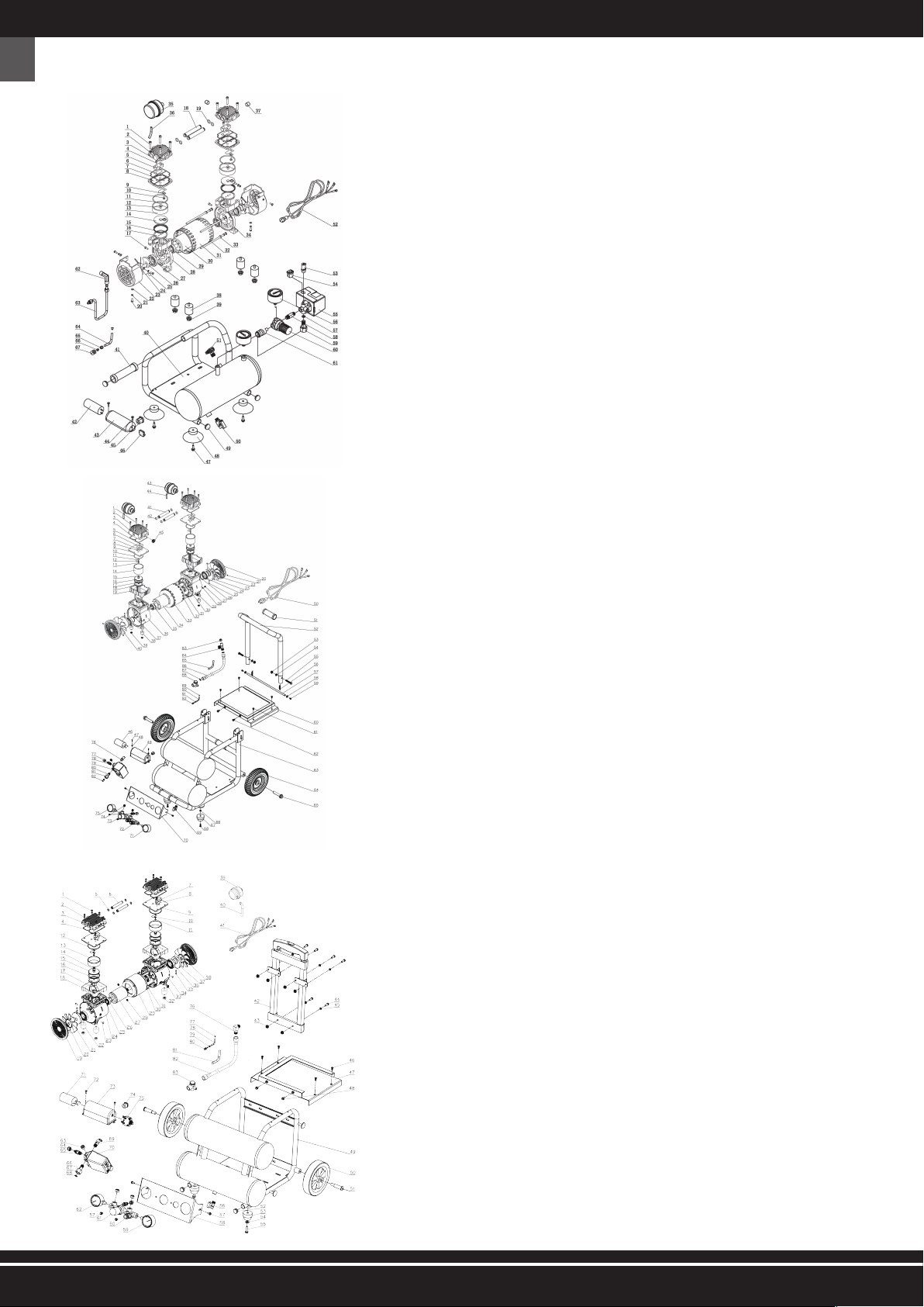
1- DENOMINATION OF THE COMPONENTS
GB
AC4504
52 ) Power Cord
53 ) Safty Valve
54 ) Power Cord Buckle
55 ) Pressure Switch
56 ) Pressure Gauge
57 ) Gasket
58 ) Double Joint
59 ) Flexible Joint
60 ) Regulator Valve
61 ) Quick Connect
62 ) Elbow
63 ) Exhaust Pipe(Al)
64 ) Unloading Pipe
65 ) Cutting Sleeve
66 ) Lining
67 ) Nut
01 ) Screw
02 ) Cushion
03 ) Cylinder Head
04 ) Screw
05 ) Limit Range Implement
06 ) Valve Block
07 ) Seal
08 ) Valve Board
09 ) Valve plate clamp
10 ) Screw
11 ) O-Ring
12 ) Screw
13 ) Cylinder
14 ) Valve Board
15 ) Piston Cup
16 ) Connecting Rod
17 ) Screw
18 ) Gas-guide Tube
19 ) O-ring
20 ) Screw
21 ) Cushion
22 ) Flat washer
23 ) Wind Scooper
24 ) Fan
25 ) Screw
26 ) Crank
27 ) Bearing
28 ) Left Crankcase
29 ) Bearing
30 ) Motor Rator
31 ) Motor Staotr
32 ) Bolt
33 ) Flat washer
34 ) Right Crankcase
35 ) Air Filter
36 ) Hush Pipe
37 ) Choke plug
38 ) Shock Pad
39 ) Nut
40 ) Horizontal Tank
41 ) Handle Sleeve
42 ) Capacity
43 ) Capacity Cover
44 ) Screw
45 ) Power Cord Buckle
46 ) Protector
47 ) Scew
48 ) Foot Pad
49 ) Apertural Plug
50 ) Ball Valve
51 ) Check Valve
2wercS)10
2noihsuC)20
03) Cylinder Head
2laeS)4
0
05) Screw
06) Limit Range Implement
07) Valve Block
3kcolBevlaV)8
0
3draoBevlaV)90
10) O-Ring
3kcolBevlaV)1
1
3pmalcetalpevlaV)21
13) Screw
3rednilyC)4
1
3wercS)51
3draoBevlaV)61
4puCnotsiP)71
18) Connecting Rod
4gninilehtgninethgieH)9
1
4repoocSdniW)02
4wercS)12
4naFA)22
lenaptnemurtsnI)07
eguaGerusserP)17
72) Quick Connect
evlaVrotalugeR)37
74) Screw
75) Pressure Gauge
76) Safty Valve
tuN)77
tniojthgiarts)87
79) Pressure Switch
tnioJelbixelF)08
tuNtnioJelbixelF)18
82) Gasket
retratStfoS)38
yaw-eerhT)48
epiPnolyN)58
epiPtsuahxE)68
87) Seal cushion
evlaVkcehC)88
gniniL)98
epiPgnidaolnU)09
eveelSgnittuC)1
9
tuN)29
wercS)7
rehsawtalF)8
49) Capacity Cover
droCrewoP)0
51) Handle Sleeve
52) Handle
53) Nut
rehsawtalF)4
tloB)5
56) Extension Spring
doRdnaH)7
rehsawtalF)8
59) Screw
etalPlooT)0
wercS)1
tloB)2
knaT)3
64) Foot Wheel
tfahsleehW)5
rehsawtalF)6
daPtooF)7
tloB)8
evlaVllaB)9
4
4
5
5
5
5
5
6
6
6
6
6
6
6
6
6
gniraeB)4
wercS)5
26) circlip for shaft
wercS)7
28) Serrated Lock Washers Internal Teeth
29) Power Cord Buckle
30) Right Crankcase
noihsuC)1
tloB)2
33) Motor Staotr
rotaRrotoM)4
gnira
eB)5
36) Left Crankcase
tuN)7
daPkcohS)8
tuN)9
naFB)0
41) Gas-guide Tube
gniR-O)2
ret
liFriA)3
epiPHush)4
gulP)5
yticapaC)64knarC)3
2
AC24016
AC12810
01) Screw
02) Flat washer
03) Cylinder Head
04) Cylinder sealing gasket
05) O-Ring
06) Gas-GuideTube
07) Limit Range Implement
08) Valve Block
09) Valve Board
10) Valve plate clamp
11) Screw
12) O-Ring
13) Cylinder
14) Screw
15) Valve Board
16) Piston Cup
17) Connecting Rod
18) Heightening the lining
19) Wind Scooper
20) CirclipforShaft
21) B Fan
22) Shock Pad
23) Screw
24) Left Crankcase
25) Screw
26) Bearing
27) Motor Rator
28) Nut
29) Motor Staotr
30) Cushion
31) Bolt
32) Nut
33) Power Cord Buckle
34) Right Crankcase
35) Screw
36) Bearing
37) Crank
38) A Fan
39) Air Filter
40) Nylon Pipe
41) Power Cord
42) Handle Pull Rod
43) Nut
44) Screw
45) Washer
46) Screw
47) Tool Board
48) Bolt
49) Horizontal Two Tank
50) Foot Wheel
51) Wheel Shaft
52) Plug (rubber)
53) Foot Pad
54) Washer
55) Bolt
56) Drain Valve
57) Bolt
58) InstrumentPanel
59) Pressure Gauge
60) Quick Connect
61) Regulator Valve Stand
62) Pressure Gauge
63) Screw
64) Nut
65) Straight connection
66) Flexible Joint
67) Flexible Joint Nut
68) Gasket
69) Safty Valve
70) Pressure Switch
71) Capacity
72) Screw
73) Capacity Cover
74) Power Cord Buckle
75) Protector
76) Elbow
77) Lining
78) Nylon Pipe
79) Cutting Sleeve
80) Nut
81) Nylon Pipe
82) Exhaust Pipe
83) Check Valve

This manual of “Use and Maintenance Instructions” was drawn up according to the provisions foreseen by the “Machinery Directive” 2006/42/EC in order to assure an easy and correct comprehension of the
contents handled by the authorized operators charged with the use and with the maintenance of this machine. Should the above mentioned operators detect any incomprehension while reading, please apply
immediately to the manufacturer for correct explanations and further information in order to avoid wrong personal interpreting that could endanger safety. This manual must at any time be available for the
authorized operators. Therefore, it must always be placed, well guarded and preserved, near to the machine
CE Marking (FIG. 2 - Ref. 1) certifies the compliance of the machine with the essential safety and health requirements foreseen by the Machinery Directive 2006/42/CE. This plate (FIG. 2 - Ref. 2) certifies
the compliance of the machine with the essential safety and health requirements foreseen by the Directive 2000/14/CE. They are represented by an adhesive plate in polyester with black stamp by thermal
transfer and they are stuck on the engine panel.
3
5- ADDRESSEES
This technical manualis destined exclusively to authorized operators charged with the use and maintenanceofthe machine according to the specific technical and professional competences required for the
type of intervention involved.
The symbols here below are placed at the beginning of a paragraph and indicate the operator involved in the handled topic.
THE AUTHORIZED OPERATORS MUST PERFORM ON THE MACHINE ONLY THE INTERVENTIONS OF THEIR SPECIFIC COMPETENCE.
BEFORE PERFORMING ANY INTERVENTIO N ON THE MACHINE, THE AUTHORIZED OPERATORS MUST MAKE SURE THEY ARE IN FULL POSSESSION OF THEIR PSYCHICAL AND
PHYSICAL FACULTIES IN ORDER TO ASSURE AT ANY TIME THE RESPECT OF THE SAFETY CONDITIONS.
GB
2- TECHNICAL DATA
Power voltage / Frequency V / Hz 230 / 50
Rated power kW 0.24
Max. operation pressure bar 8
Assured noise pressure level (Dir. 2000/14/CE) dB 58
Motor shaft rotation speed rpm 1420
Tank volume litres 4
Yield (sucked / delivered) l/min 45 / 28
Ambient air temperature / humidity °C / % 5 - 40 / 5 - 95
Overall weight kg 10.5
Dimensions (bxlxh) mm 355x335x300
4- THE IMPORTANCE OF THE HANDBOOK
BEFORE USING THIS MACHINE, THE AUTHORIZED OPERATORS (SEE PAR. 2.2.1) MUST READ AND UNDERSTAND THIS MANUAL IN ALL ITS PARTS.
THIS MANUAL IS INTEGRAL PART OF THE MACHINE AND MUST BE PRESERVED FOR FUTURE REFERENCE UNTIL DISPOSAL OF THE SAME. THIS MANUAL MUST ALWAYS BE AVAIL-
ABLE FOR THE CHARGED OPERATORS AND HAS TO BE PLACED WELL STORED AND PRESERVED NEAR TO THE MACHINE.
THE MANUFACTURER CANNOT BE MADE LIABLE FOR DAMAGES TO PERSONS, ANIMALS AND THINGS, DUE TO THE INOBSERVANCE OF THE STANDARDS AND OF THE INSTRUC-
TIONS DESCRIBED IN THIS MANUAL.
THIS MANUAL HAS COMPULSORILY TO BE DELIVERED TOGETHER WITH THE MACHINE, IN CASE THIS LATTER IS TRANSFERRED TO ANOTHER USER.
THIS MANUAL MEETS THE STATE OF ART WHEN THE MACHINE IS TRADED AND CANNOT BE CONSIDERED IMPROPER JUST BECAUSE FOLLOWING TO NEW EXPERIENCES IT CAN
THEN BE UPDATED.
IN CASE OF LOSS OR WEAR OF THE MANUAL, REQUEST A NEW COPY FROM THE MANUFACTURER OR AUTHORIZED DEALER SPECIFYING THE MODEL OF THE MACHINE AND THE
REVISION QUOTED ON THE COVER.
3- CE MARKING AND PLATE OF ASSURED SOUND PRESSURE LEVEL
Power voltage / Frequency V / Hz 230 / 50
Rated power kW 1.5
Max. operation pressure bar 9
Assured noise pressure level (Dir. 2000/14/CE) dB 72
Motor shaft rotation speed rpm 1400
Tank volume litres 16
Yield (sucked / delivered) l/min 240 / 170
Ambient air temperature / humidity °C / % 5 - 40 / 5 - 95
Overall weight kg 42.5
Dimensions (bxlxh) mm 720x510x500
Power voltage / Frequency V / Hz 230 / 50
Rated power kW 0.75
Max. operation pressure bar 9
Assured noise pressure level (Dir. 2000/14/CE) dB 65
Motor shaft rotation speed rpm 1420
Tank volume litres 10
Yield (sucked / delivered) l/min 128/80
Ambient air temperature / humidity °C / % 5 - 40 / 5 - 95
Overall weight kg 25.8
Dimensions (bxlxh) mm 540X465X495
CHARGED OPERATOR: this is an operator being at least 18 years old (private user or worker), who, in compliance with the provisions of the laws in force in the country of use on safety and
health in work places, can perform exclusively the switching-on, use and switching-off of the machine in full observance of the instructions contained in this manual, being equipped with the
personal protection equipment.
MECHANICAL / PNEUMATIC MAINTENANCE ENGINEER: this is a trained technical engineer qualified to perform exclusively interventions on mechanical / pneumatic parts in order to carry out
adjustment, maintenance and/or repair procedures even with disabled protections in full observance of the instructions contained in this manual or in any another specific document exclusively
supplied by the manufacturer, being equipped with the personal protection equipment.
ELECTRICAL MAINTENANCE ENGINEER: this is a trained technical engineer qualified to perform intervention exclusively on electrical devices in order to carry out adjustment, maintenance
and or repair procedures also with live voltage and with disabled protections in full observance of the instructions contained in this manual or in another specific document exclusively supplied
by the manufacturer, being equipped with personal protection equipment.
COMPANY SAFETY MANAGER: this is a qualified technical engineer, appointed by the employer (in case the machine is used in a company), meeting the technical and professional requirements
foreseen by the regulations in force concerning the safety and health of workers in the place ofwork.
MANUFACTURER’S TECHNICAL ENGINEER: this is a qualified technical engineer supplied by the Manufacturer and/or authorized Dealer to perform the required technical assistance, as well
as interventions of routine and supplementary maintenance and/or procedures not described in this manuaL requiring a specific knowledge of the machine, being equipped with the personal
protection equipment.

4
IT IS STRICTLY FORBIDDEN TO COMMISSION THE MACHINE IN ENVIRONMENTS WITH POTENTIALLY EXPLOSIVE ATMOSPHERE AND/OR IN PRESENCE OF COMBUSTIBLE DUSTS
(EX.: WOOD DUSTS, FLOURS, SUGARS AND MIDDLINGS).
LIMITATIONS IN USE: IT IS STRICTLY FORBIDDEN TO USE THE MACHINE FOR IMPROPER USES, DIFFERING FROM THE FORESEEN ONE (PAR. 9).
IT IS COMPULSORY TO KEEP THE MACHINE OUT OF THE REACH OF CHILDREN.
DURING THE USE, IT IS COMPULSORY TO VERIFY THAT NON-AUTHORIZED PEOPLE DO NOT GET CLOSE TO THE MACHINE.
IT IS STRICTLY FORBIDDEN TO USE AIR TUBES (EXTENSIONS), FITTINGS, AND TOOLS NOT SUITABLE AND/OR NOT COMPLYING WITH THE REGULATIONS IN FORCE.
IT IS STRICTLY FORBIDDEN TO LIFT THE MACHINE WITH CRANES AND/OR FORK LIFT TRUCKS.
IT IS STRICTLY FORBIDDEN TO DIRECT COMPRESSED AIR JETS AGAINST PERSONS, ANIMALS AND THINGS.
IT IS STRICTLY FORBIDDEN TO USE THE MACHINE TO TRANSPORT AND/OR LIFT PERSONS, ANIMALS AND THINGS.
IT IS STRICTLY FORBIDDEN TO GET ON THE MACHINE.
IT IS STRICTLY FORBIDDEN TO TOW THE MACHINE BY ANY MEANS AND/OR VEHICLE WHATSOEVER.
IT IS STRICTLY FORBIDDEN TO MOVE THE MACHINE MANUALLY ON UPWARDS AND/OR DOWNWARDS SLOPES WITH HAZARDOUS GRADE.
HAZARD OF BURNING BY ACCIDENTAL CONTACT WITH THE BI-CYLINDRICAL PUMPING ASSEMBLY AND THE ELECTRIC MOTOR. CAUTION! THERE IS A RESIDUAL RISK (SEE
PAR.21).
GB 6- STATE OF “SWITCHED OFF MACHINE”
Before performing any type of maintenance and/or adjustment intervention on the machine, it is necessary to drain compulsorily the tank (no pressure), to disconnect power supply
source, as well as to verify that the machine is actually stopped and cannot be switched on suddenly (ON-OFF switch on pos. “OFF (0)” and power supply cable disconnected from
the mains outlet and positioned close to the machine).
7- WARRANTY
1) DECLARATION OF WARRANTY: the manufacturer undertakes towards the purchaser to replace, repair or otherwise intervene on the machine, in case of conformity defects jeopardizing its
correct use and operation, exclusively if such defects are due to the actual responsibility of the manufacturer. The manufacturer reserves the right of adopting the best solution to restore
the compliance of the machine within a reasonable period of time.
2) PURCHASER: the purchaser is called “consumer” when the purchase is carried out by an individual acting for purposes not belonging to his/her business or professional activity.
The purchaser is called “professional man/woman or company” when the purchase is carried out by a professional man/woman or by a company acting for purposes belonging to his/her/
its business or professional activity.
3) TERMS: the manufacturer is liable when the conformity defect arises within the following terms from the purchasing date; 24 months, if the purchase has been carried out by a “con-
sumer”, as described under point 2); 12 months, if the purchase has been carried out by a “professional man/woman or company”, as described under point 2);
4) VALIDITY: the warranty is valid whenthe purchaser notifies to the manufacturer the conformity defect within 2 months from the date in which such defect was first remarked. Such notice
must compulsorily be submitted together with a valid purchasing document (cash slip or invoice).
5) EXPIRATION: the warranty expires if the purchaser uses the machine improperly and/or in a way not complying with the instructions for use and maintenance supplied by the manufacturer,
or if the conformity defect has been caused by purchaser’s lack of skill or by chance.
6) RESPONSIBILITY: the manufacturer cannot be made liable for any liability following any possible damages to the purchasers resulting from loss of or diminished production due to possible
conformity defects.
7) EXPENSES: Expenses related to labour and materials necessary to restore the conformity of the machine are at manufacturer’s charge. Expenses and delivery terms are to be agreed upon
with the authorized dealer.
8- RESERVED RIGHTS
The reserved rights on this manual “use and maintenance instructions” remain property of the manufacturer. None part of this manual can be reproduced and disclosed (totally or partially) by
any reproduction means without written authorization of the Manufacturer. All quoted trademarks belong to the respective owners.
9- DESTINATION OF USE
FIELD OF USE Industrial, craft and civil sector.
PLACE OF USE Indoor or outdoor places (provided that it is not subject to atmospheric agents) sufficiently
lighted, ventilated, with ambient air temperature and humidity values complying with par. 2,
suitable in compliance with the law provisions in force in the country of use on safety and
health in the places of work. The machine has to lean on a surface assuring its stability with
reference to its weight and its overall dimensions (see par. 2).
CAUTION! IT IS COMPULSORY TO KEEP THE MACHINE OUT OF THE REACH OF CHILDREN.
FORESEEN USE Air compression (without oil) for the use of suitable pneumatic tools complying with the regu-
lations in force. (ex.: guns for blowing, inflation, washing, painting or sandblasting; screwers;
spot welders, riveters or greasers).
OPERATORS CHARGED WITH THE USE An authorized operator meeting the professional requirements described in par. 5.
10- USE LIMITS
This machine was designed and produced exclusively for the intended use described in par. 9, any other use and operation is therefore absolutely forbidden in order to assure in every moment
the safety of the charged operators, as well as the efficiency of the machine itself.
5
16- ELECTRICAL CONNECTIONS
The machine can be connected to the mains by inserting the power supply plug in the proper outlet.
THE MAINS TO WHICH THE MACHINE IS CONNECTED MUST COMPLY WITH THE REQUIREMENTS FORESEEN BY THE REGULATION IN FORCE IN THE COUNTRY OF USE, AS WELL AS
MEET THE TECHNICAL FEATURES QUOTED IN PAR.2 AND BE EQUIPPED WITH A PROPER “EARTHING” PLANT.
ANY TYPE OF ELECTRIC MATERIAL USED FOR THE CONNECTION MUST SUIT THE USE, BE MARKED “CE” IF SUBJECT TO THE LOW VOLTAGE DIRECTIVE 2006/95/EC, AND COMPLY
WITH THE REQUIREMENTS SET FORTH BY THE REGULATIONS IN FORCE IN THE COUNTRY OF USE OF THE MACHINE.
THE INOBSERVANCE OF THE ABOVE DESCRIBED WARNINGS CAN CAUSE IRREPARABLE DAMAGES TO THE ELECTRIC EQUIPMENT OF THE MACHINE AND THE FOLLOWING
EXPIRATION OF THE WARRANTY.
THE MANUFACTURERS DECLINES ALL LIABILITY FOR FAULTS OR MALFUNCTIONS OF THE MACHINE DUE TO VOLTAGE SUDDEN CHANGES EXCEEDING THE TOLERANCES FORE-
SEEN BY THE DISTRIBUTING ENTITY (VOLTAGE ±10% - FREQUENCY ±2%).
SHOULD IT BE NECESSARY, IT IS COMPULSORY TO CONNECT THE MACHINE EXCLUSIVELY TO GENERATING SETS WITH A POWER GREATER THAN THE INSTALLED ELECTRIC
POWER (SEE PAR. 2) TO SUPPORT THE ABSORPTION PEAK AT START.
17- CONNECTION OF THE AIR TUBE (EXTENSION) AND OF THE TOOLS
1) Connect the tool to the air tube (extension);
2) Connect the air tube (extension) to the fast air outlet tap of the machine (FIG. 1 - Ref. 14).
IT IS STRICTLY FORBIDDEN TO USE AIR TUBES (EXTENSIONS), FITTINGS, AND TOOLS NOT SUITABLE AND/OR NOT COMPLYING WITH THE REGULATIONS IN FORCE.
IT IS COMPULSORY TO USE AIR TUBES (EXTENSIONS), FITTINGS, AND TOOLS, COMPLYING WITH THE PROVISIONS CONTAINED IN THE USE AND MAINTENANCE INSTRUCTIONS
SUPPLIED BY THE RELATED MANUFACTURERS.
THE MANUFACTURERDECLINESALL LIABILITYFOR DAMAGESTO PERSONS, ANIMALS AND THINGSDUETO THEINOBSERVANCEOF THEABOVE DESCRIBED WARNINGS.
GB
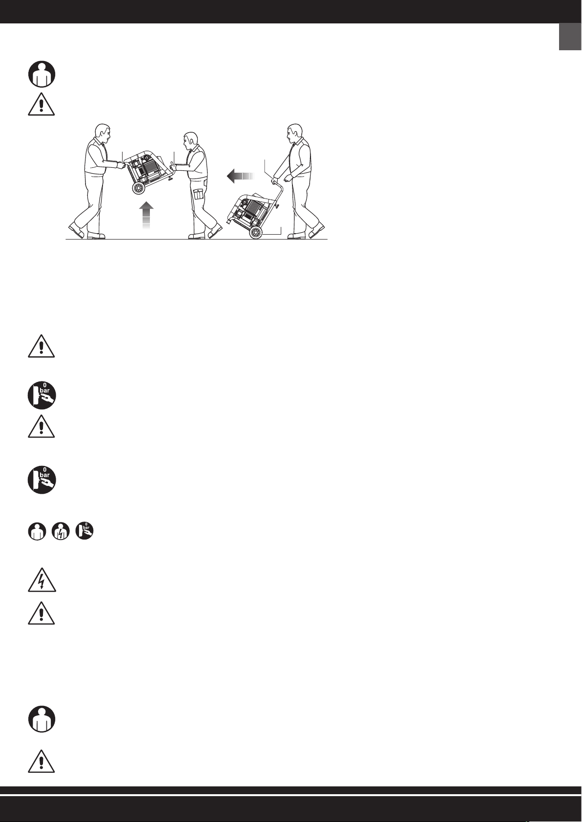
11- MACHINE TRANSPORT AND HANDLING
The machine can be transported manually by two charged operators by seizing it by the bearing foot (FIG. 3 - Ref. 1) and the handle (FIG. 3 - Ref. 2) or handled manually by a
charged operator using the handle (FIG. 3 - Ref. 3) and the wheels (FIG. 3 - Ref. 4) with which it is equipped.
THE TRANSPORT OF THE MACHINE MUST COMPULSORILY BE CARRIED OUT BY TWO CHARGED OPERATORS IN COMPLIANCE WITH THE REGULATIONS ON THE “MANUAL HAN-
DLING OF LOADS”, IN ORDER TO AVOID UNFAVOURABLE ERGONOMIC CONDITIONS THAT MAY INVOLVE RISKS OF SPINE/LUMBAR LESIONS.
12- PACKAGING
The machine is packed by the Manufacturer in a cardboard box equipped with two handles and containing No.1 Dry compressor and No.1 Use and maintenance instructions.
13- UNPACKAGING
Once the package has been positioned on the floor, on an even surface assuring its stability, unpack the machine removing it from the package observing the instructions contained in par. 12.
IT IS RECOMMENDED TO DISPOSE THE PACKAGE ACCORDING TO THE DIFFERENT TYPES OF MATERIALS IN FULL OBSERVANCE OF THE LAWS IN FORCE IN THE COUNTRY OF USE.
14- POSITIONING
The machine must be used in a work place having the features described in par. 2, positioned on an even floor assuring its stability in relation to its overall dimensions and weight
(par. 2).
IN ORDER TO ALLOW THE AUTHORIZED OPERATORS TO WORK IN SAFETY PLACES, IT IS SUGGESTED TO ASSURE A MINIMUM DISTANCE (1 m) FROM OTHERS OBJECTS AND/OR
OBSTRUCTIONS.
15- STORAGE
If the machine is not used for long time, it is necessary to store it in a safe place, provided with proper temperature and humidity, as well as to protect it against dust.
Before storing the machine, it is recommended to drain the condensate from the air tank.
1 2
3
4
Fig. 3
6
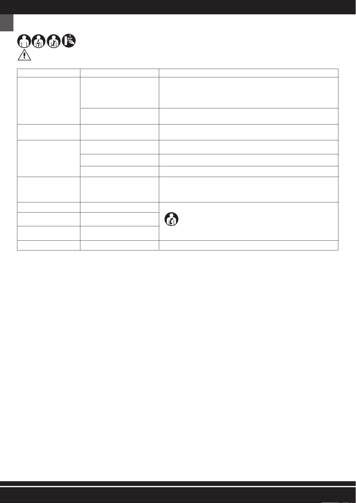
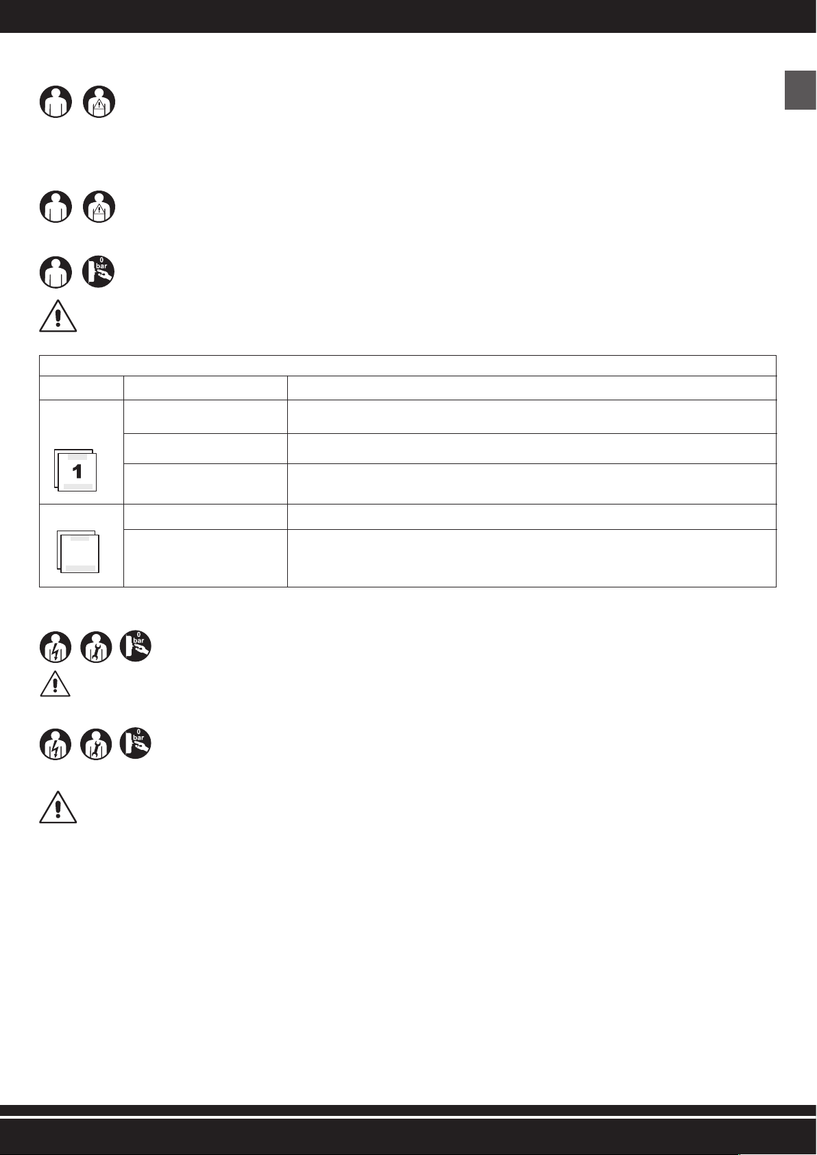
20- PERSONAL PROTECTION EQUIPMENT (PPE)
THE AUTHORIZED OPERATORS ARE NOT ALLOWED TO WEAR CLOTHS AND ACCESSORIES THAT MAY BE ENTANGLED IN THE MACHINE.
IT IS COMPULSORY TO USE THE PPE FORESEEN BY THE MANUFACTURER.
THE AUTHORIZED OPERATORS MUST COMPULSORILY USE THE PPE FORESEEN BY THE MANUFACTURERS OF THE TOOLS USED AND ACCORDING TO THE PROCESSING TYPE.
SIGNAL COMPULSORY PPETYPE OF USE
sHands Protection
(Heat protecting gloves)
In case maintenance interventions are required without waiting that the electric motor and the bi-cylindrical
pumping element cool down.
sHearing Protection (Ear muff) During all processing phases.
sFeet protection (Footwear with reinforced cap) During machine transport.
21- RESIDUAL RISKS
The authorized operators shall be aware that even though the manufacturer has adopted all possible technical manufacturing precautions to make the machine safe, there is still a potential
residual risk.
RESIDUAL RISK Hazard of burning by accidental contact with the bi-cylindrical pumping assembly and the electric motor.
EXPOSURE FREQUENCY Low and accidental. There can be exposure if the operator decides to perform voluntary a wrong action, forbidden and not reasonably foreseeable.
DAMAGE RELEVANCE Light lesions (usually reversible).
TAKEN MEASURES Safety signs (see par. 19). / Obligation of use of the personal protection equipment (PPE) (see par. 20) and/or wait until the machine has cooled.
GB 18- APPLIED SAFETY DEVICES
1) SAFETY VALVE (FIG. 1 - Ref. 4): this is a certified safety valve (calibrated on 10,5 bar), installed on the pneumatic plant under the pressure switch. It is used to discharge the overpressure
of the plant, when the pressure switch does not work due to possible malfunctions. The tripping of the safety valve obliges the operator to switch off the machine and require the interven-
tion of the maintenance technical engineers.
2) PRESSURE SWITCH (FIG. 1 - Ref. 8): this is an electro-pneumatic device (calibrated on min. 7 bar and max. 10 bar) installed on the pneumatic plant. It is used to command the automatic
start of the machine, when the operation pressure falls under 7 bar, as well as the automatic stop when the operation pressure reaches 10 bars.
3) FIXED PROTECTION GRATING OF THE COOLING FAN (FIG. 1 - Ref. 17): This is affixed protection made up of a grating in plastic material fastened by screws to the base of the bi-cylindrical
pumping assembly. It is used to avoid accidental contact with the moving cooling fan.
4) RESTORABLE THERMAL SWITCH (FIG. 1 - Ref. 12): this is a thermal protection installed on the electric plant, stopping the electric motor in case of current overload and/or short-circuit.
The restoration can be performed by the related push-button (see FIG. 7 - Ref. 1).
5) TANK PRESSURE GAUGE (FIG. 1 - Ref. 6): this is a measuring device installed on the machine tank. It displays the compressed air pressure present within the tank.
6) PRESSURE GAUGE AT OUTPUT (FIG. 1 - Ref. 7): this is a measuring device installed on the machine pneumatic plant upstream of the fast air outlet tap. It displays the output pressure,
which is adjustable through the proper pressure regulator (0 ÷ 10 bar) (FIG. 1 - Ref. 13).
IT IS STRICTLY FORBIDDEN TO TAMPER, DISCONNECT AND/OR REMOVE ANY SAFETY DEVICE EXISTING IN THE MACHINE.
IT IS STRICTLY FORBIDDEN TO REPLACE ANY SAFETY DEVICE OR ANY OF THEIR COMPONENTS WITH NOT ORIGINAL SPARE PARTS.
IT IS COMPULSORY TO CHECK CONSTANTLY THE CORRECT OPERATION OF ALL SAFETY DEVICES INSTALLED ON THE MACHINE.
IT IS COMPULSORY TO IMMEDIATELY REPLACE ANY SAFETY DEVICE MALFUNCTIONING AND/OR BEING DAMAGED.
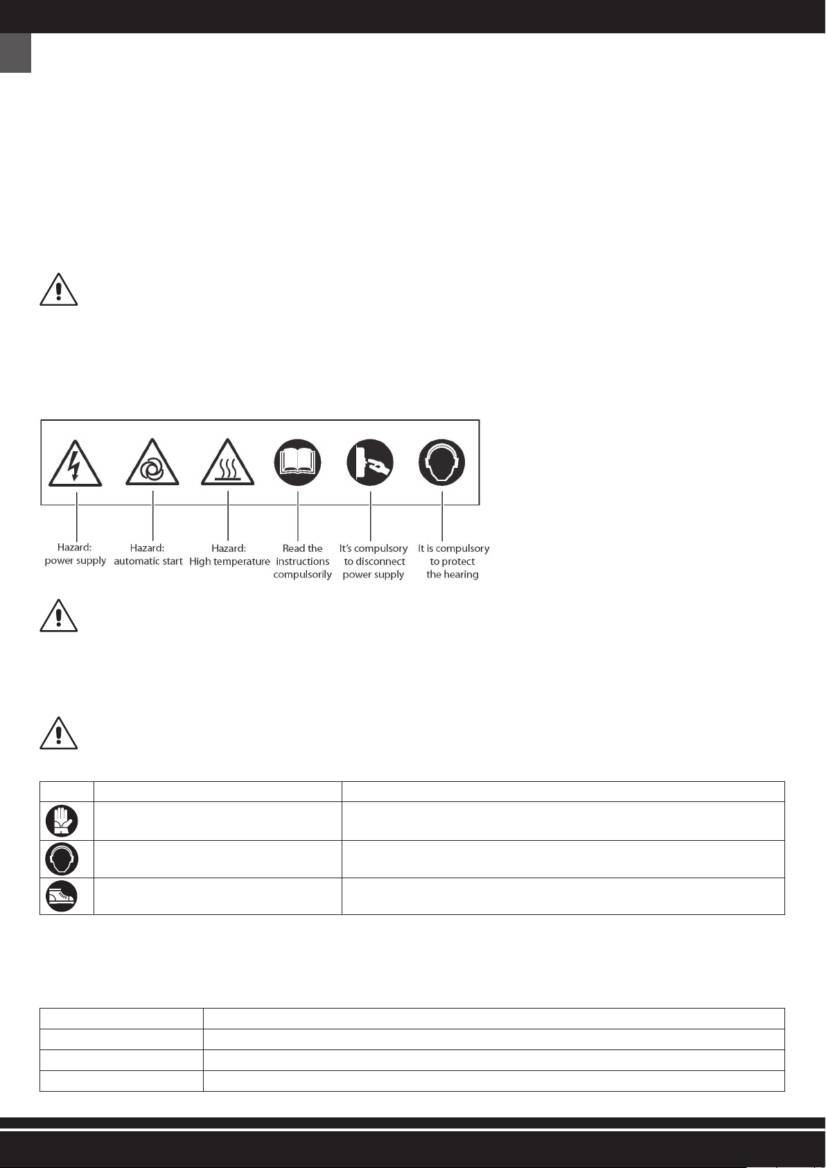
19- SAFETY MARKING
The safety marking used, is represented by an adhesive label, applied on the outside of the machine (FIG. 4).
Meaning of the signals:
IT IS COMPULSORY TO KEEP THE SAFETY SIGNALS WELL CLEAN TO ENSURE THEIR GOOD VISIBILITY.
IT IS ABSOLUTELY FORBIDDEN TO REMOVE AND/OR DAMAGE THE SAFETY SIGNALS APPLIED TO THE MACHINE.
IT IS COMPULSORY TO REPLACE THE SAFETY SIGNALS WORN OUT REQUESTING IT TO THE MANUFACTURER AND/OR AUTHORIZED DEALER.
Hazard:
power supply
Hazard:
automatic start
Hazard:
High temperature
Read the
instructions
compulsorily
It’s compulsory
to disconnect
power supply
It is compulsory
to protect
the hearing

7
1) Connect the machine to the mains by inserting the power supply plug (FIG. 5 - Ref. 1) in the proper outlet;
2) Switch on the machine by pulling the “ON-OFF” switch (FIG. 5 - Ref. 3) in pos. “ON (I)” (the machine works until the max. operation pressure of 10 bar is reached, then it stops
automatically);
3) Adjust pressure at output using the proper regulator (FIG. 5 - Ref. 4), according to the used tool and to the type of processing. Check pressure in the proper pressure gauge
(FIG. 5 - Ref. 6);
IT IS FORBIDDEN TO SCREW THE PRESSURE REGULATOR AT OUTPUT (FIG. 8 - REF. 3) BEYOND THE END OF STROKE, IN ORDER TO AVOID DAMAGING THE MEMBRANE.
4) Connect the tool to the air tube (extension);
5) Connect the air tube (extension) to the fast air outlet tap of the machine (FIG. 5 - Ref. 5);
IT IS STRICTLY FORBIDDEN TO USE AIR TUBES (EXTENSIONS), FITTINGS, AND TOOLS NOT SUITABLE AND/OR NOT COMPLYING WITH THE REGULATIONS IN FORCE.
IT IS COMPULSORY TO USE AIR TUBES (EXTENSIONS), FITTINGS, AND TOOLS, COMPLYING WITH THE PROVISIONS CONTAINED IN THE USE AND MAINTENANCE INSTRUCTIONS
SUPPLIED BY THE RELATED MANUFACTURERS.
6) Perform the processing (the machine restarts automatically when the operation pressure falls under 7 bar);
7) Once the processing has ended, switch off the machine as described in par. 25.
25- MACHINE SWITCHING OFF
At the end of the work cycle, switch off the machine as follows:
1) Switch off the machine by pressing the “ON-OFF” switch (FIG. 5 - Ref. 3) on pos. “OFF (0)”;
2) Disconnect the machine from the mains by removing the power supply plug (FIG. 5 - Ref. 1) from the proper outlet;
3) Disconnect the tool from the air tube (extension);
4) Disconnect the air tube (extension) from the fast air outlet tap (FIG. 5 - Ref. 5) of the machine;
5) Drain the condensate from the tank only in case of work cycle end (FIG. 1 - Ref. 5).
GB
22- COMMAND DEVICES
They are shown in FIG. 5.
1) Power supply cable
2) Pressure switch
3) “ON-OFF” switch
4) Pressure regulator at output
5) Fast air outlet tapa
6) Pressure gauge at output
7) Tank pressure gauge
23- CHECKS BEFORE SWITCHING ON
BEFORE SWITCHING-ON OF THE MACHINE, THE AUTHORIZED OPERATORS MUST COMPULSORY PERFORM THE FOLLOWING CHECKS.
1) Make sure that there are not any non authorized person close to the machine.
2) Make sure that the safety device are integral and properly installed and working (see par. 18).
3) Make sure that the machine is properly positioned (see par. 14).
4) Make sure that the “ON-OFF” switch or selector is positioned on “OFF (0)” (see par. 22).
5) Make sure that the condensate drain valve is closed (FIG. 1 - Ref. 5).
6) Use the compulsory personal protection devices (PPE) (see par. 20).
7) Make sure that you have read and understood the “Use and Maintenance Instructions” in all its parts.
24- MACHINE SWITCHING-ON
THE AUTHORIZED OPERATORS CAN SWITCH ON THE MACHINE ONLY AFTER HAVING COMPULSORILY PERFORMED THE CHECKS DESCRIBED IN PAR. 23.
BEFORE USING THIS MACHINE, THE AUTHORIZED OPERATORS MUST READ AND UNDERSTAND THIS MANUAL IN ALL ITS PART.
DURING THE USE, IT IS COMPULSORY TO VERIFY THAT NON-AUTHORIZED PEOPLE DO NOT GET CLOSE TO THE MACHINE.
THE AUTHORIZED OPERATORS ARE NOT ALLOWED TO LET THE MACHINE UNATTENDED DURING OPERATION AND MAINTENANCE INTERVENTIONS.
HAZARD OF BURNING BY ACCIDENTAL CONTACT WITH THE BI-CYLINDRICAL PUMPING ASSEMBLY AND THE ELECTRIC MOTOR. CAUTION! THERE IS A RESIDUAL RISK (SEE PAR. 21).
THE MANUFACTURER DECLINES ALL LIABILITY FOR DAMAGES TO PERSONS, ANIMALS AND THINGS, DUE TO THE INOBSERVANCE OF THE STANDARDS AND WARNINGS DE-
SCRIBED IN THIS MANUAL.
THE MANUFACTURER DECLINES ALL LIABILITIES ON THE FINAL RESULT OF THE PROCESSING GIVEN THAT IT DEPENDS EXCLUSIVELY ON THE TYPE OF TOOL USED AND ON THE
PROFESSIONAL SKILLS OF THE AUTHORIZED OPERATORS.
Fig. 5
7 6
ON
OFF
10
2
7
1
6
543

8
ROUTINE MAINTENANCE TABLE
FREQUENCYPOINT OF INTERVENTIONTYPE OF INTERVENTION
EVERY DAY Safety devices Make sure that they are integral, properly installed and working.
Power supply cable and plugVisual check of the wear state.
Tank At every work cycle end lean the machine on the ground and drain the condensate from the tank, opening the
condensate valve (FIG. 1 - Ref. 5).
EVERY WEEKWheels Tire pressure control. If necessary, inflate with compressed air up to max. 2.5 bar
No.2 Air filters, front and rear sideUnscrew the screws (FIG. 6 - Ref. 1);
Remove the cover (FIG. 6 - Ref. 2);
Estract the filter (FIG. 6 - Ref. 3) and clean it with air;
Re-assemble the cover properly.
N.B.: REPLACE IN CASE OF CLEAR WEAR.
30- SUPPLEMENTARY MAINTENANCE
It includes all activities performed in order to maintain the proper use and operation conditions of the machine through different types of interventions (adjust-
ments, replacements, etc.) carried out exclusively by the technicians of the manufacturer at the established frequency or in case of failure or wear.
FOR ANY SUPPLEMENTARY MAINTENANCE INTERVENTION, COMPULSORY REQUEST THE TECHNICAL ASSISTANCE TO THE MANUFACTURER OF THE AUTHORIZED DEALER.
31- DEMOLITION
When the machine is demolished, compulsorily observe the provisions of the regulations in force.
Separate the parts making up the machine according to the different construction materials (plastic, copper, iron, etc.).
32- SPARE PARTS
ORIGINAL SPARE PARTS FOR POSSIBLE REPLACEMENTS ARE TO BE REQUESTED EXCLUSIVELY TO THE MANUFACTURER OR TO THE AUTHORIZED DEALER.
IT IS STRICTLY FORBIDDEN TO REPLACE ANY COMPONENTS OF THE MACHINE WITH NOT ORIGINAL SPARE PARTS.
7
GB 26- RESTORABLE THERMAL PROTECTION TRIPPING RESET
Should a current overload and/or a short-circuit occur in the electric plant of the machine, the restorable thermal switch trips stopping the electric motor. To reset the
restorable thermal switch, proceed as follows:
1) Press the “ON-OFF” switch (FIG. 5 - Ref. 3) on pos.“OFF (0)”;
2) Press the restorable thermal push-button (FIG. 7 - Ref. 1);
3) Before restarting the machine wait some minutes.
SHOULD THE MACHINE AFTER HAVING PERFORMED THE RESET NOT SWITCH ON, THE CHARGED OPERATOR MUST COMPULSORY SEEK THE INTERVENTION OF THE MAINTE-
NANCE TECHNICAL ENGINEERS AND/OR OF THE AUTHORIZED DEALER.
27- EMERGENCY STOP
The switching-off of the machine can be performed by pressing the “ON-OFF” switch (FIG. 5 - Ref. 3) on pos. “OFF (0)”. In order to avoid situations of imminent or close
hazard, the authorized operators must compulsorily perform the following operations:
1) PRESS THE “ON-OFF” SWITCH (FIG. 5 - REF. 3) ON POS. “OFF (0)” IN THE RIGHT TIME.
2) IMMEDIATELY INFORM THE “SAFETY MANAGER” OF THE EMERGENCY (IF THE MACHINE IS USED IN A COMPANY).
28- SWITCHING ON AFTER AN EMERGENCY STOP
Only and exclusively after having removed the emergency causes and having carefully assessed that the same have not caused damages and/or anomalies to the
machine, with the consent of the “Safety Manager” (in case the machine is used in a company), switch on the machine as described in par. 24.
29- ROUTINE MAINTENANCE
It includes all activities performed in order to maintain the proper use and operation conditions of the machine through different types of intervention (adjustments, visual
checks, cleaning of air filters, etc.) carried out by the authorized maintenance technical engineer at the established frequency.
THE AUTHORIZED OPERATORS MUST PERFORM EXCLUSIVELY THE OPERATIONS OF THEIR SPECIFIC COMPETENCE (SEE PAR. 5) AND WITH THE CONSENT OF THE COMPANY
SAFETY MANAGER (IF THE MACHINE IS USED IN A COMPANY).
THE AUTHORIZED OPERATORS ARE NOT ALLOWED TO LEAVE THE MACHINE UNATTENDED DURING ITS OPERATION AND DURING MAINTENANCE OPERATIONS.
9
33- TROUBLE - CAUSES - TROUBLESHOOTING
The following table gives a series of situations that can occur during the use of the machine.
THE AUTHORIZED OPERATORS MUST PERFORM EXCLUSIVELY THE OPERATIONS OF THEIR SPECIFIC COMPETENCE (SEE PAR. 2.2.1) AND WITH THE CONSENT OF THE COMPANY
SAFETY MANAGER (IF THE MACHINE IS USED IN A COMPANY).
TROUBLE CAUSES TROUBLESHOOTING
The machine does not switch on
or stops and does not restart.
Lack of power supply.
Tripping of the restorable thermal switch due
to current overload and/or short-circuit.
1) Make sure that the “ON-OFF” switch is on pos. “ON (I)”;
2) Check that the power supply cable plug is working and properly inserted in the suitable outlet;
3) Check that possible extensions used and the power supply outlet are working;
4) Check that the main switch of the mains is working and positioned on “ON (I)”.
Follow the procedure described in par. 26.
The machine starts many times
without using the tool.
Leaks from the air tube, the tool or the
pneumatic plant.
1) Check that the pneumatic plant has not been damaged;
2) Check the integrity and the connection of the air tube and of the tool.
Air does not come out from the
tool.
The tank is not under pressure.
Wrong adjustment of the output pressure.
The tool is damaged.
Switch on the machine and wait until the tank is loaded verifying the pressure on the proper pressure
gauge.
Check that the value indicated on the pressure gauge at output is greater than 0 (zero) bar.
Check the integrity and efficiency of the tool.
Pressure decrease in the air tank.Leaks from the air tube, the tool or the
pneumatic plant.
1) Check the integrity of the pneumatic plant.
2) Check the integrity of the air tube and of the tool.
3) Verify that the machine-air tube and air tube-tool connections are right.
4) Make sure that the condensate drain valve is well closed.
Tripping of the safety valve. Pressure switch faulty.
Air leak from the valve of the pres-
sure switch with stopped machine.Check valve dirty or worn. Apply to an authorized dealer.
The machine vibrates and/or emits
a lot of noise. Mechanical break.
Frequent starts and low yield.Air filters dirty. Clean the filters (see par. 29).
GB

10
FR
1- NOM DES COMPOSANTS
54 ) Power Cord Buckle
55 ) Pressure Switch
56 ) Pressure Gauge
57 ) Gasket
58 ) Double Joint
59 ) Flexible Joint
60 ) Regulator Valve
61 ) Quick Connect
62 ) Elbow
63 ) Exhaust Pipe(Al)
64 ) Unloading Pipe
65 ) Cutting Sleeve
66 ) Lining
67 ) Nut
03 ) Cylinder Head
04 ) Screw
05 ) Limit Range Implement
06 ) Valve Block
07 ) Seal
08 ) Valve Board
09 ) Valve plate clamp
10 ) Screw
11 ) O-Ring
12 ) Screw
13 ) Cylinder
14 ) Valve Board
15 ) Piston Cup
16 ) Connecting Rod
17 ) Screw
20 ) Screw
21 ) Cushion
22 ) Flat washer
23 ) Wind Scooper
24 ) Fan
25 ) Screw
26 ) Crank
27 ) Bearing
28 ) Left Crankcase
29 ) Bearing
30 ) Motor Rator
31 ) Motor Staotr
32 ) Bolt
33 ) Flat washer
34 ) Right Crankcase
37 ) Choke plug
38 ) Shock Pad
39 ) Nut
40 ) Horizontal Tank
41 ) Handle Sleeve
42 ) Capacity
43 ) Capacity Cover
44 ) Screw
45 ) Power Cord Buckle
46 ) Protector
47 ) Scew
48 ) Foot Pad
49 ) Apertural Plug
50 ) Ball Valve
51 ) Check Valve
2wercS)10
2noihsuC)20
03) Cylinder Head
2laeS)4
0
05) Screw
06) Limit Range Implement
07) Valve Block
3kcolBevlaV)8
0
3draoBevlaV)90
10) O-Ring
3kcolBevlaV)1
1
3pmalcetalpevlaV)21
13) Screw
3rednilyC)4
1
3wercS)51
3draoBevlaV)61
4puCnotsiP)71
18) Connecting Rod
4gninilehtgninethgieH)9
1
4repoocSdniW)02
4wercS)12
4naFA)22
lenaptnemurtsnI)07
eguaGerusserP)17
72) Quick Connect
evlaVrotalugeR)37
74) Screw
75) Pressure Gauge
76) Safty Valve
tuN)77
tniojthgiarts)87
79) Pressure Switch
tnioJelbixelF)08
tuNtnioJelbixelF)18
82) Gasket
retratStfoS)38
yaw-eerhT)48
epiPnolyN)58
epiPtsuahxE)68
87) Seal cushion
evlaVkcehC)88
gniniL)98
epiPgnidaolnU)09
eveelSgnittuC)1
9
tuN)29
wercS)7
rehsawtalF)8
49) Capacity Cover
droCrewoP)0
51) Handle Sleeve
52) Handle
53) Nut
rehsawtalF)4
tloB)5
56) Extension Spring
doRdnaH)7
rehsawtalF)8
59) Screw
etalPlooT)0
wercS)1
tloB)2
knaT)3
64) Foot Wheel
tfahsleehW)5
rehsawtalF)6
daPtooF)7
tloB)8
evlaVllaB)9
4
4
5
5
5
5
5
6
6
6
6
6
6
6
6
6
gniraeB)4
wercS)5
26) circlip for shaft
wercS)7
28) Serrated Lock Washers Internal Teeth
29) Power Cord Buckle
30) Right Crankcase
noihsuC)1
tloB)2
33) Motor Staotr
rotaRrotoM)4
gnira
eB)5
36) Left Crankcase
tuN)7
daPkcohS)8
tuN)9
naFB)0
41) Gas-guide Tube
gniR-O)2
ret
liFriA)3
epiPHush)4
gulP)5
yticapaC)64knarC)3
2
AC24016
AC12810
01) Screw
02) Flat washer
03) Cylinder Head
04) Cylinder sealing gasket
05) O-Ring
06) Gas-GuideTube
07) Limit Range Implement
08) Valve Block
09) Valve Board
10) Valve plate clamp
11) Screw
12) O-Ring
13) Cylinder
14) Screw
15) Valve Board
16) Piston Cup
17) Connecting Rod
18) Heightening the lining
19) Wind Scooper
20) CirclipforShaft
21) B Fan
22) Shock Pad
23) Screw
24) Left Crankcase
25) Screw
26) Bearing
27) Motor Rator
28) Nut
29) Motor Staotr
30) Cushion
31) Bolt
32) Nut
33) Power Cord Buckle
34) Right Crankcase
35) Screw
36) Bearing
37) Crank
38) A Fan
39) Air Filter
40) Nylon Pipe
41) Power Cord
42) Handle Pull Rod
43) Nut
44) Screw
45) Washer
46) Screw
47) Tool Board
48) Bolt
49) Horizontal Two Tank
50) Foot Wheel
51) Wheel Shaft
52) Plug (rubber)
53) Foot Pad
54) Washer
55) Bolt
56) Drain Valve
57) Bolt
58) InstrumentPanel
59) Pressure Gauge
60) Quick Connect
61) Regulator Valve Stand
62) Pressure Gauge
63) Screw
64) Nut
65) Straight connection
66) Flexible Joint
67) Flexible Joint Nut
68) Gasket
69) Safty Valve
70) Pressure Switch
71) Capacity
72) Screw
73) Capacity Cover
74) Power Cord Buckle
75) Protector
76) Elbow
77) Lining
78) Nylon Pipe
79) Cutting Sleeve
80) Nut
81) Nylon Pipe
82) Exhaust Pipe
83) Check Valve
AC4504
52 ) Power Cord
53 ) Safty Valve
01 ) Screw
02 ) Cushion
18 ) Gas-guide Tube
19 ) O-ring
35 ) Air Filter
36 ) Hush Pipe

11
FR
5- DESTINATAIRES
LES OPÉRATEURS AUTORISES DOIVENT RÉALISER SUR LA MACHINE EXCLUSIVEMENT LES INTERVENTIONS DE LEUR COMPÉTENCE SPÉCIFIQUE.
LES OPÉRATEURS AUTORISÉS AVANT DE RÉALISER TOUTE INTERVENTI ONS SUR LA MACHINE DOIVENT S’ASSURER D’AVOIR LES PLEINES FACULTÉS PSYCHIQUES ET PHYSIQUES
TELLES A’ GARANTIR TOUJOURS LE RESPECT DES CONDITIONS DE SÉCURITE’.
6- ETAT “MACHINE ARRETEE”
2- DONNEES TECHNIQUES
3- MARQUAGE CE ET PLAQUE NIVEAU DE PUISSANCE SONORE GARANTI
4- IMPORTANCE DU MANUEL
AVANT D’UTILISER LA MACHINE EN OBJET IL EST OBLIGATOIRE POUR LES OPERATEURS DE LIRE ET COMPRENDRE DANS TOUTES SES PARTIES CES INSTRUCTIONS POUR
L’EMPLOI ET L’ENTRETIEN.
CES INSTRUCTIONS SONT UNE PARTIE INTEGRANTE DE LA MACHINE ET DOIVENT OBLIGATOIREMENT ETRE GARDEES POUR TOUTE REFERENCE FUTURE JUSQU’A’ SA DEMOLI-
TION. CE MANUEL DOIT TOUJOURS ETRE A DISPOSITION DES OPERATEURS PREPOSES ET DOIT ETRE PRES DE LA MACHINE, BIEN GARDE’.
LE PRODUCTEUR N’A AUCUNE RESPONSABILITE’ POUR DOMMAGES A PERSONNES,ANIMAUX ET CHOSES, CAUSES PAR LE NON RESPECT DES NORMES ET AVERTISSEMENTS
DECRITS DANS CES INSTRUCTIONS.
CES INSTRUCTIONS DOIVENT ETRE OBLIGATOIREMENT DELIVREES AVEC LA MACHINE SI ON LA CEDE A UN AUTRE UTILISATEUR.
CES INSTRUCTIONS IDENTIFIEN T L’ÉTAT DE LA TECHNIQUE AU MOMENT DE LA VENTE DE LA MACHINE ET NE PEUVENT PAS ÊTRE CONSIDÉREES NON APPROPRIEES UNIQUE-
MENT PARCE QUE SELON LES NOUVELLES EXPÉRIENCES ELLES PEUVENT ÊTRE MISES A JOUR PAR LA SUITE.
EN CAS DE PERTE OU DÉTÉRIORATION DU MANUEL IL FAUT EN DEMANDER UNE COPIE AU PRODUCTEUR, EN SPÉCIFIANT LE MODÈLE DE LA MACHINE ET LA RÉVISION INDIQUÉE
DANS L’EN TETE.
Tension de alimentation électrique / Fréquence V / Hz 230 / 50
Puissance nominale 0.24
Pression maxi de service 8
Niveau de puissance sonore garanti (Dir. 2000/14/CE) 58
Vitesse rotation arbre moteur 1420
Volume réservoir 4
Rendement (aspirés / rendus) 45 / 28
Température / Humidité air ambiant
5- 40 / 5 - 95
Poids total 10.5
Dimensions (bxlxh)
355x335x300
AC4504
V / Hz 230 / 50
Niveau de puissance sonore garanti (Dir. 2000/14/CE)
Tension de alimentation électrique / Fréquence
Puissance nominale
Pression maxi de service
Vitesse rotation arbre moteur
Volume réservoir
Rendement (aspirés / rendus)
Température / Humidité air ambiant
Poids total
Dimensions (bxlxh)
1.5
9
72
1400
16
240 / 170
5 - 40 / 5 - 95
42.5
720x510x500
AC24016
Tension de alimentation électrique / Fréquence V / Hz 230 / 50
Puissance nominale
Pression maxi de service
Niveau de puissance sonore garanti (Dir. 2000/14/CE)
Vitesse rotation arbre moteur
Volume réservoir
Rendement (aspirés / rendus)
Température / Humidité air ambiant
Poids total
Dimensions (bxlxh)
AC12810
Ces “Instructions pour l’emploi et l’entretien” ont été rèdigées selon les indications prévues par la Directive Machines 2006/42/CE , dans le but de garantir une facile et correcte compréhension des sujets
traités, de la part des opérateurs chargés de l’emploi et entretien de la machine en objet. Si les opérateurs susdits trouvent quelque incompréhension dans la lecture, on vous prie, pour éviter de mauvaises
interprétations compromettant la sécurité de demander immédiatement au Producteur les explications correctes et d’autres renseignements. Les “Instructions pour l’emploi et l’entretien” doivent être, en tout
moment, à disposition des opérateurs autorisés et se trouver bien gardées toujours près de la machine.
Ces “Instructions pour l’emploi et l’entretien” sont destinées exclusivement aux opérateurs autorisés pour l’emploi et l’entretien de la machine selon les compétences spécifiques techniques et professionnelles
demandées pour le type d’intervention. Les symboles indiqués ci-dessous sont disposés au début d’un chapitreet/ou paragraphe pour indiquer quel est l’opérateur intéressé à l’argument traité.
Le marquage CE (FIG. 2 -Rif. 1) certifie la conformité de la machine aux conditions essentielles de sécurité et santé prévues par la Directive Machines 2006/42/CE. Le plaque niveau de puissance sonore
garanti (FIG. 2 -Rif. 2) , certifie la conformité de la machine aux conditions essentielles de sécurité et santé prévues par la Directive 2000/14/CE. Le plaque niveau de puissance sonore garanti (Fig. 2),
certifie la conformité de la machine aux conditions essentielles de sécurité et santé prévues par la Directive 2000/14/CE. Elles se composent d’une plaquette adhésive en polyester, avec impression par
transfer thermique couleur noire et sont appliquées sur le panneau du moteur.
0.75
9
65
1420
10
128/80
5 - 40 / 5 - 95
25.8
540X465X495
OPERATEUR PREPOSÉ: C’est un opérateur ayant 18 ans (usager privé ou travailleur) et qui, en conformité avec ce qui est prévu par la législation en vigueur dans le pays d’emploi en matière
de sécurité et santé dans les lieux de travail, soit à même de réaliser exclusivement la mise en marche, l’emploi et l’arrêt de la machine dans le respect absolu des instructions indiquées dans
ce manuel, muni des dispositifs de protection individuelle.
TECHNICIEN D’ENTRETIEN MECANIQUE / PNEUMATIQUE: C’est un technicien qualifié habilité pour réaliser exclusivement des interventions sur les dispositifs mécaniques/pneumatiques pour
effectuer réglages, entretiens et/ou réparations même avec les protections non habilitées, dans le respect absolu des instructions ici indiquées ou dans un autre document spécifique fourni
exclusivement par le producteur, muni des dispositifs de protection individuelle.
TECHNICIEN D’ENTRETIEN ELECTRIQUE: C’est un technicien qualifié habilité pour réaliser exclusivement des interventions sur les dispositifs électriques pour effectuer réglages, entretiens et/ou
réparations même en présence de tension électrique et avec les protections non habilitées, dans le respect absolu des instructions ici indiquées ou dans un autre document spécifique fourni
exclusivement par le producteur, muni des dispositifs de protection individuelle.
RESPONSABLE DE LA SECURITE DE LA SOCIETE’: C’est un technicien qualifié désigné par l’employeur (si on utilise la machine dans le domaine de l’usine) et ayant les capacités techniques et
professionnelles demandées par les normes en vigueur en matière de sécurité et de santé des travailleurs sur les postes de travail.
TECHNICIEN DU PRODUCTEUR: C’est un technicien qualifié mis à disposition par le Producteur et/ou par le Vendeur autorisé pour effectuer l’assistance technique demandée, interventions
d’entretien extraordinaire et/ou opérations non indiquées ici demandant une connaissance spécifique de la machine, muni des dispositifs de protection individuelle.
Avant toute intervention et/ou réglage sur la machine, il est obligatoire de vider le réservoir (absence de pression), sectionner la source d’alimentation électrique, s’assurer que la machine soit
effectivement arrêtée et qu’il n’y a pas un démarrage non prévu (interrupteur “ON-OFF” dans la pos. “OFF (0)” et câble d’alimentation électrique débranché de la prise de réseau et positionné
près de la machine.
kW
bar
dB
rpm
litres
kg
mm
l/min
°C / %
kW
bar
dB
rpm
litres
kg
mm
l/min
°C / %
kW
bar
dB
rpm
litres
kg
mm
l/min
°C / %

12
FR
ON INTERDIT ABSOLUMENT LA MISE EN SERVICE DE LA MACHINE DANS DES ENVIRONNEMENTS AVEC ATMOSPHÈRE POTENTIELLEMENT EXPLOSIVE ET/OU EN PRÉSENCE DE
POUSSIÈRES COMBUSTIBLES (EX. POUSSIÈRES DE BOIS, FARINES, SUCRES ET GRAINS).
LIMITATIONS DANS L’EMPLOI: L’UTILISATION DE LA MACHINE EST UNIQUEMENT AUTORISÉ DANS DES ENDROITS PRÉVUS AU PARAGRAPHE 9.
IL EST OBLIGATOIRE DE TENIR LA MACHINE HORS DE LA PORTÉE DES ENFANTS.
PENDANT L’EMPLOI IL FAUT VEILLER CONSTAMMENT À CE QUE DES PERSONNES NON AUTORISÉES NE S’APPROCHENT PAS DE LA MACHINE.
ON INTERDIT ABSOLUMENT L’EMPLOI DE TUYAUX D’AIR (RALLONGES), RACCORDS ET OUTILS NON APPROPRIÉS ET/OU NON-CONFORMES AUX NORMES EN VIGUEUR.
ON INTERDIT ABSOLUMENT DE LEVER LA MACHINE AVEC GRUE ET/OU CHARIOT ÉLÉVATEUR.
ON INTERDIT ABSOLUMENT DE DIRIGER DES JETS D’AIR COMPRIME’ CONTRE LES PERSONNES, ANIMAUX ET CHOSES.
ON INTERDIT ABSOLUMENT D’UTILISER LA MACHINE POUR LE TRANSPORT ET/OU LE LEVAGE DE PERSONNES, ANIMAUX ET CHOSES.
ON INTERDIT ABSOLUMENT DE MONTER SUR LA MACHINE.
ON INTERDIT ABSOLUMENT DE TRAINER LA MACHINE AVEC TOUT MOYEN ET/OU VÉHICULE.
ON INTERDIT ABSOLUMENT DE METTRE EN MOUVEMENT LA MACHINE SUR DES DESCENTES ET/OU PENTES DANGEREUSES.
DANGER DE BRULURES PAR CONTACT ACCIDENTEL AVEC LE GROUPE POMPANT BICYLINDRIQUE ET MOTEUR ÉLECTRIQUE. ATTENTION, IL Y A UN RISQUE RÉSIDUEL (V. PAR. 21).
7- GARANTIE
1) DECLARATION DE GARANTIE: Le producteur s’engage vis-à-vis de l’acheteur à remplacer, réparer ou intervenir autrement sur la machine si elle présente des défauts de conformité com-
promettant son emploi et fonctionnement corrects, exclusivement si ces défauts sont dus à l’effective responsabilité du producteur. Le producteur se réserve le droit d’adopter la solution la
meilleure pour rétablir la conformité de la machine dans une période de temps raisonnable.
2) ACHETEUR: L’acheteur se définit “consommateur” lorsque l’achat est effectué par une personne physique qui agit pour les buts inclus dans le domaine de son activité commerciale ou pro-
fessionnelle; L’acheteur se définit “professionnel ou bien compagnie” lorsque l’achat est effectué par un professionnel ou bien une maison agissant pour les buts inclus dans le domaine
de son activité commerciale ou professionnelle;
3) TERMES: Le producteur est responsable lorsque le défaut de conformité se manifeste dans les termes suivants dès la date d’achat: 24 mois si l’achat a été effectué par un “consomma-
teur” commedécrit au point 2); 12 mois si l’achat a été effectué par un “professionnel ou une compagnie” comme décrit au point 2);
4) VALIDITE’: La garantie est valable lorsque l’acheteur dénonce au producteur le défaut de conformité dans 2 mois dès la date dans laquelle il a relevé ce défaut. Cette dénonciation doit être
obligatoirement accompagnée par un document d’achat régulier (reçu fiscal ou facture).
5) ECHEANCE: La garantie échoit au cas où l’acheteur utilise la machine d’une façon impropre et/ou non conforme aux instructions pour l’emploi et l’entretien fournie par le producteur, ou
bien au cas où le défaut de conformité était causé par faute d’expertise de l’acheteur.
6) RESPONSABILITE’: Le producteur est exonéré de toute responsabilité conséquente d’éventuels dommages créés à l’acheteur, dérivant d’une faute ou d’une perte de production, con-
séquents à éventuels défauts de conformité.
7) FRAIS: Les frais relatifs à la main d’œuvre et aux matériaux, nécessaires pour le rétablissement de la conformité de la machine, sont à la charge du Producteur. Les frais et les modalités
d’envoi sont à agréer avec le Vendeur Autorisé.
8- DROITS RESERVES
Les droits réservés concernant ce manuel “INSTRUCTIONS POUR L’EMPLOI ET L’ENTRETIEN” restent propriété du Producteur. Aucune partie des “instructions pour l’emploi et l’entretien” ne peut
être reproduite et diffusée (complètement ou partiellement) avec n’importe quel moyen, sans l’autorisation écrite du Producteur.
9- DESTINATION D’EMPLOI
TYPE D’EMPLOI Industriel, artisanal et civil.
LIEU D’EMPLOI Lieux fermés ou ouverts, (non exposés aux intempéries) suffisamment ventilés, illuminés, avec valeurs de température et humidité de
l’air ambiant indiqués en par. 2 prévus pour les dispositions législatives en vigueur dans le pays d’emploi en matière de sécurité et
santé dans les lieux de travail. La machine doit être positionnée sur un sol plat, en assurant sa stabilité en proportion avec le poids et
les dimensions générales (par. 2) . ATTENTION! IL EST OBLIGATOIRE DE TENIR LA MACHINE HORS DE LA PORTEE DES ENFANTS.
EMPLOI PREVU Compression de l’air (sans huile) pour l’emploi d’outils pneumatiques appropriés et conformes aux normes en vigueur
(Ex.: soufflettes, gonflage, lavage, vernissage ou sablage, etc...).
OPERATEURS PREPOSES POUR L’EMPLOI Un opérateur autorisé ayant les capacités techniques et professionnelles décrités au par. 5.
10- LIMITATIONS DANS L’EMPLOI
La machine a été construite et réalisée exclusivement pour la destination d’emploi indiquée au par. 9 , donc il est absolument interdit tout autre emploi, dans le but de garantir en tout moment la
sécurité des opérateurs préposés et l’efficacité de la même.

13
FR
16- CONNEXION ELECTRIQUE
On peut brancher la machine au réseau d’alimentation électrique en introduisant la fiche du câble d’alimentation électrique dans la prise appropriée.
LE RESEAU D’ALIMENTATION ELECTRIQUE AUQUEL EST BRANCHE LA MACHINE DOIT ETRE CONFORME AUX CONDITIONS PREVUES PAR LA LEGISLATION EN VIGUEUR DANS LE
PAYS D’EMPLOI, SATISFAIRE LES CARACTERISTIQUES TECHNIQUES DE LA PAR. 2 ET AVOIR UNE INSTALLATION DE “MISE A TERRE” APPROPRIEE.
TOUTE TYPE DE MATÉRIAU ÉLECTRIQUE UTILISE’ POUR LA CONNEXION DOIT ÊTRE APPROPRIE’ POUR L’EMPLOI, MARQUE’ “CE” SI SOUMIS A’ LA DIRECTIVE BASSE TENSION
2006/95/CE ET CONFORME AUX CONDITIONS DEMANDÉES PAR LES NORMES EN VIGUEUR DANS LE PAYS D’EMPLOI DE LA MACHINE.
LE NON RESPECT DES AVERTISSEMENTS MENTIONNÉS CI-DESSOUS PEUT CAUSER DES DOMMAGES IRRÉPARABLES AU PANNEAU ÉLECTRIQUE DE LA MACHINE AVEC UNE
ÉCHÉANCE DE LA GARANTIE.
LE PRODUCTEUR N’A AUCUNE RESPONSABILITE’ POUR PANNES OU ANOMALIES DE FONCTIONNEMENT DE LA MACHINE CAUSES PAR DES DIFFERENCES DE TENSION ELEC-
TRIQUE AU DE LA DES TOLERANCES PREVUES PAR L’ORGANISME DISTRIBUTEUR (TENSION ±10% -FREQUENCE ±2%).
S’IL EST NECESSAIRE, IL EST OBLIGATOIRE DE CONNECTER LA MACHINE EXCLUSIVEMENT A’ DES GÉNÉRATEURS DE COURANT ÉLECTRIQUE AVEC PUISSANCES PLUS GRANDES
DE LA PUISSANCE ELECTRIQUE INSTALLE (V. PAR. 2), POUR SUPPORTER LE DÉPART DU COURANT DE DÉMARRAGE.
17- CONNEXION DU TUYAU DE L’AIR (RALLONGE) ET DES OUTILS
1) Connecter l’outil au tuyau de l’air (rallonge);
2) Connecter le tuyau de l’air (rallonge) au robinet rapide de sortie de l’air de la machine (FIG. 1 -Réf. 14).
ON INTERDIT ABSOLUMENT L’EMPLOI DE TUYAUX D’AIR (RALLONGES), RACCORDS ET OUTILS NON APPROPRIÉS ET NON-CONFORMES AUX NORMES EN VIGUEUR.
IL EST OBLIGATOIRE D’UTILISER DES TUYAUX D’AIR (RALLONGES), RACCORDS ET OUTILS, EN CONFORMITE’ AVEC CE QUI EST PREVU PAR LES INSTRUCTIONS POUR L’EMPLOI
ET L’ENTRETIEN FOURNIES PAR LES RELATIFS PRODUCTEURS.
LE PRODUCTEUR DECLINE TOUTE RESPONSABILITE POUR D’ÉVENTUELS DOMMAGES A PERSONNES, ANIMAUX ET CHOSES, CAUSES PAR LE NON RESPECT DES AVERTISSE-
MENTS SUSDITS.
11- TRANSPORT ET MANUTENTION DE LA MACHINE
La machine peut être transportée manuellement par deux opérateurs préposés en la prenant par le pied (FIG. 3 -Réf. 1) et par la poignée (FIG. 4 -Réf. 2) ou manipulée manuelle-
ment par un opérateur préposé par la poignée (FIG. 3 -Réf. 3) et les roues (FIG. 3 -Réf. 4) dont elle est équipée.
LE TRANSPORT DE LA MACHINE DOIT ETRE OBLIGATOIREMENT REALISE PAR DEUX OPERATEURS PREPOSES DANS LE RESPECT DES NORMES SUR LE “MOUVEMENT MANUEL
DES CHARGES” POUR EVITER DES CONDITIONS ERGONOMIQUES DEFAVORABLES COMPORTANT DES RISQUES DE LESIONS AU DOS.
12- EMBALLAGE
La machine est emballée par le producteur dans une boite de carton munie de deux poignées et contenant: N. 1 Compresseur et
N. 1 Instructions pour l’emploi et l’entretien.
13- DEBALLAGE
Une fois positionné l’emballage à terre sur une surface plate qui en assure sa stabilité il faut procéder au déballage en enlevant la machine depuis l’emballage dans le respect des indications du
par. 11.
ON RECOMMANDE D’ÉLIMINER L’EMBALLAGE SELON LES DIFFÉRENTES TYPOLOGIES DE MATÉRIAU DANS LE RESPECT ABSOLU DE LA LÉGISLATION EN VIGUEUR DANS LE PAYS
D’EMPLOI.
14- POSITIONNEMENT
La machine doit être positionnée dans un lieu de travail avec les caractéristiques décrites au par. 2 , positionnée sur un sol plat, en assurant sa stabilité en proportion avec le poids
et les dimensions générales (par. 2) .
POUR ASSURER AUX OPERATEURS AUTORISES LA POSSIBILITE’ D’OPERER EN SECURITE’, ON CONSEILLE DE POSITIONNER LA MACHINE A LA DISTANCE MINIMALE DE 1 m
DEPUIS AUTRES OBJETS ET/OU ENCOMBREMENTS.
15- STOCKAGE
Au cas où la machine ne soit pas utilisée pendant une longue période de temps, il faut la stocker dans un endroit sûr, avec un
degré de température et humidité appropriés; il faut aussi la protéger de la poussière.
On conseille, avant stockage de la machine, de purger la condensation du réservoir d’air.
1 2
3
4
Fig. 3

14
FR
20- DISPOSITIFS DE PROTECTION INDIVIDUELLE (DPI)
ON INTERDIT AUX OPÉRATEURS AUTORISES DE VETIR DES VETEMENTS ET ACCESSOIRES POUVANT RESTER ENCASTRÉS DANS LA MACHINE. IL EST OBLIGATOIRE DE UTILISER
LES DPI PRÉVUS PAR LE PRODUCTEUR.
IL EST OBLIGATOIRE QUE LES OPERATEURS AUTORISES UTILISENT LES DPI PREVUS PAR LES PRODUCTEURS DES OUTILS UTILISES ET SUR LA BASE DU TYPE FONCTIONNEMENT.
SIGNALEDPI OBLIGATOIRES TYPE D’EMPLOI
sProtection des mains (Gants antichaleur) Si on demande de l'entretien sans attendre que le moteur électrique et le groupe de compression bicylindre se refroidit.
sProtection de l'ouï (Casques) Pendant toutes les phases de fonctionnement.
sProtection des pieds
(Chaussures avec pointe renforcée)
Pendant le transport de la machine.
21- RISQUES RESIDUELS
On informe les opérateurs préposés que méme si le producteur a utilisé toutes les précautions techniques constructives possibles pour rendre la machine sure, il y a encore un potentiel risque
résiduel.
RISQUE RESIDUEL Danger de brûlures par contact accidentel avec le groupe de compression bicylindre et moteur électrique.
FREQUENCE D’EXPOSITION Basse et accidentelle. Il peut y avoir exposition si l’opérateur décide de réaliser volontairement une action EXPOSITION incorrecte, interdite et non
raisonnablement prévoyable.
DIMENSIONS DU DOMMAGE Lésions légères (normalement réversibles).
DISPOSITIONS ADOPTEES Signaux de sécurité (v. par. 19) ; Obligation d’utiliser les dispositifs de protection individuelle (DPI) (v. par. 20) et/ou ADOPTEES attendre le refroidis-
sement de la machine.
18- DISPOSITIFS DE SECURITÉ ADOPTES
1) VANNE DE SECURITE’ (FIG. 1 -Réf. 4): C’est une vanne de sécurité certifiée (calibrée à 10,5 bar), installée sur l’installation pneumatique au dessous du pressostat. Elle sert pour décharger
la surpression de l’installation si le pressostat, pour éventuelles anomalies, ne marche pas. L’intervention de la vanne de sécurité oblige l’opérateur à arrêter la machine et demander
l’intervention des techniciens d’entretien.
2) PRESSOSTAT (FIG. 1 -Réf. 8): C’est un dispositif électropneumatique (calibré à min. 7 bar max. 10 bar) installé sur l’installation pneumatique. Il sert pour commander le démarrage
automatique de la machine lorsque la pression d’exercice descend à 7 bar et l’arrêt automatique quand la pression d’exercice rejoint les 10 bar.
3) GRILLE DE PROTECTION FIXE VENTILATEUR DE REFROIDISSEMENT (FIG. 1 -Réf. 17): C’est une protection fixe constituée par une grille en matériau plastique fixée avec des vis à la base
du groupe pompant bi-cilyndrique. Elle sert pour empêcher le contact accidentel avec le ventilateur de refroidissement en mouvement.
4) DISJONCTEUR THERMIQUE À RÉARMEMENT (FIG. 1 -Réf. 12): C’est une protection thermique installée sur l’installation électrique qui arrête le moteur électrique en cas de surcharge de
courant et/ou court circuit. On peut réaliser le rétablissement à l’aide du bouton de réarmement (v. FIG. 7 -Réf. 1) .
5) MANOMETRE PRESSION RESERVOIR (FIG. 1 -Réf. 6): C’est un dispositif de mesurage installé sur le réservoir de la machine. Il affiche la pression de l’air comprimé à l’intérieur du réservoir.
6) MANOMETRE PRESSION EN SORTIE (FIG. 1 -Réf. 7): C’est un dispositifde mesurage installé sur l’installation pneumatique de la machine en amont du robinet rapide de sortie air. Il affiche
la pression à la sortie, réglable à travers le régulateur de pression approprié (0 à 10 bar) (FIG. 1 -Réf. 13) .
IL EST ABSOLUMENT INTERDIT DE MANIPULER, EXCLURE ET/OU ENLEVER TOUT DISPOSITIF DE SECURITE’ EXISTANT DANS LA MACHINE.
IL EST ABSOLUMENT INTERDIT DE REMPLACER TOUT DISPOSITIF DE SECURITE’ OU BIEN UN DE SES COMPOSANTS AVEC DES PIECES DE RECHANGE NON ORIGINALES.
IL EST OBLIGATOIRE DE CONTROLER CONSTAMMENT LE BON FONCTIONNEMENT DE TOUS LES DISPOSITIFS DE SECURITE’ INSTALLES DANS LA MACHINE.
IL EST OBLIGATOIRE DE REMPLACER IMMEDIATEMENT LES EVENTUELS DISPOSITIFS DE SECURITE DE MAUVAIS FONCTIONNEMENT ET/OU ENDOMMAGES.
19- SIGNAUX DE SECURITÉ
Les signaux de sécurité utilisés se composent d’une étiquette adhésive, appliquée à l‘extérieur de la machine (FIG. 4).
Signification des symboles:
IL EST OBLIGATOIRE DE MAINTENIR BIEN PROPRES LES SIGNAUX DE SECURITÉ POUR GARANTIR LA BONNE VISIBILITÉ.
IL EST ABSOLUMENT INTERDIT D’ENLEVER OU ENDOMMAGER LES SIGNAUX DE SECURITE’ APPLIQUÉS À LA MACHINE.
IL EST OBLIGATOIRE DE REMPLACER LES SIGNAUX DE SECURITE’ DETERIORES, EN LES DEMANDANT AU PRODUCTEUR ET/OU VENDEUR AUTORISÉ.
Danger
courant
électrique
Danger
démarrage
automatique
Danger
haute
température
Obligation
de lire les
instructions
Obligation
de débrancher
la tension
Obligation
de protéger l’ouï

15
FR
1) On peut brancher la machine au réseau d’alimentation électrique en introduisant la fiche du câble d’alimentation électrique (FIG. 5 -Réf. 1) dans la prise appropriée;
2) Allumer la machine en tirant l’interrupteur “ON-OFF” (FIG. 5 -Réf.
3) en pos.“ON (I)” (la machine fonctionne jusqu’à atteindre la pression max. d’exercice de 10 bar, après elle s’arrête automatiquement); 3) Régler la pression à la sortie en utilisant
le régulateur approprié (FIG. 5 -Réf. 4) , selon l’outil utilisé et le type d’usinage. Contrôler la pression dans le manomètre approprié (FIG. 5 -Réf. 6) ;
ON INTERDIT DE VISSER OUTRE LE FIN DE COURSE LE REGULATEUR DE PRESSION EN SORTIE (FIG. 5 -RÉF. 4) POUR EVITER D’ENDOMMAGER LA MEMBRANE.
4) Connecter l’outil au tuyau de l’air (rallonge);
5) Connecter le tuyau de l’air (rallonge) au robinet rapide de sortie de l’air de la machine (FIG. 5 - RÉF. 5) ;
ON INTERDIT ABSOLUMENT L’EMPLOI DE TUYAUX D’AIR (RALLONGES), RACCORDS ET OUTILS NON-CONFORMES AUX NORMES EN VIGUEUR.
IL EST OBLIGATOIRE D’UTILISER DES TUYAUX D’AIR (RALLONGES), RACCORDS ET OUTILS, EN CONFORMITE’ AVEC CE QUI EST PREVU PAR LES INSTRUCTIONS POUR L’EMPLOI
ET L’ENTRETIEN FOURNIES PAR LES RELATIFS PRODUCTEURS.
6) Réaliser l’usinage (la machine se rallume automatiquement lorsque la pression d’exercice descend au dessous des 7 bar);
7) Une fois terminé l’usinage, éteindre la machine comme décrit au par. 25 .
25- ARRETER LA MACHINE
A la fin du cycle arrêter la machine comme suit:
1) Arrêter la machine en tirant l’interrupteur “ON-OFF” (FIG. 5 - RÉF. 3) en pos. “OFF (0)”;
2) Débrancher la machine du réseau d’alimentation électrique en débranchant la fiche du câble d’alimentation électrique (FIG. 5 -RÉF. 1) dans la prise appropriée;
3) Débrancher l’outil du tuyau de l’air (rallonge);
4) Débrancher le tuyau de l’air (rallonge) du robinet rapide de sortie de l’air (FIG. 5 -RÉF. 5) . de la machine;
5) Effectuer la purge du réservoir uniquement en cas de fin de cycle de travail (FIG. 1 -RÉF. 5) .
26- DISJONCTEUR THERMIQUE À RÉARMEMENT
S’il y a une surcharge de courant et/ou un court circuit dans l’installation électrique de la machine, le disjoncteur thermique
intervient en arrêtant le moteur électrique. Pour réaliser le reset, procéder comme suit:
1) Appuyer sur l’interrupteur “ON-OFF” (FIG. 5 -Réf. 3) en pos. “OFF (0)”;
2) Appuyer sur le bouton du disjoncteur thermique (FIG. 7 -Réf. 1) ;
3) Avant de rallumer la machine attendre quelque minute.
SI APRES AVOIR REALISE’ UN RESET LA MACHINE NE SE RALLUME PAS, L’OPERATEUR PREPOSE’ DOIT OBLIGATOIREMENT DEMANDER L’INTERVENTION DES TECHNICIENS
D’ENTRETIEN ET/OU DU VENDEUR AUTORISE’.
22- DISPOSITIFS DE COMMANDE
Les dispositifs de commande sont indiqués en FIG. 5.
1) Câble d’alimentation électrique
2) Pressostat
3) Interrupteur “ON-OFF”
4) Réglage de la pression en sortie
5) Robinet rapide sortie air
6) Manomètre de la pression en sortie
7) Manomètre pression réservoir
23- CONTRÔLES AVANT LA MISE EN MARCHE
AVANT DE RÉALISER LA MISE EN MARCHE DE LA MACHINE LES OPÉRATEURS AUTORISÉS DOIVENT OBLIGATOIREMENT RÉALISER LES CONTRÔLES INDIQUES CI DESSOUS.
1) S’assurer qu’il n’y ait pas de personnes non autorisées près de la machine.
2) S’assurer que les dispositifs de sécurité soient intègres et correctement installés et en parfait état de fonctionnement (v. par. 18) .
3) S’assurer que la machine soit correctement positionnée (v. par. 14) .
4) S’assurer que l’interrupteur ou sélecteur “ON-OFF ” soit en pos. “OFF (O)” (v. par. 22) .
5) S’assurer que la vanne de purge soit fermée (FIG. 1 - Réf. 5).
6) Utiliser les dispositifs de protection individuelle (DPI) obligatoires (par. 20) .
7) S’assurer d’avoir lu et compris dans toutes ses parties les “Instructions pour l emploi et l entretien”.
24- MISE EN MARCHE DE LA MACHINE
LES OPERATEUR AUTORISÉS PEUVENT METTRE EN MARCHE LA MACHINE UNIQUEMENT APRÈS AVOIR OBLIGATOIREMENT RÉALISE’ LES CONTRÔLES DÉCRITS AU PAR. 23.
AVANT D’UTILISER LA MACHINE EN OBJET IL EST OBLIGATOIRE POUR LES OPERATEURS DE LIRE ET COMPRENDRE DANS TOUTES SES PARTIES LE INSTRUCTIONS.
PENDANT L’UTILISATION IL FAUT VEILLER CONSTAMMENT À CE QUE DES PERSONNES NON AUTORISÉES NE S’APPROCHENT PAS DE LA MACHINE.
IL EST INTERDIT AUX OPERATEURS AUTORISES DE LAISSER SANS SURVEILLANCE LA MACHINE PENDANT LE FONCTIONNEMENT ET LES ENTRETIENS.
DANGER DE BRULURES PAR CONTACT ACCIDENTEL AVEC L’ENSEMBLE GROUPE DE COMPRESSION BICYLINDRE ET MOTEUR ÉLECTRIQUE. ATTENTION, IL Y A UN RISQUE RÉSI-
DUEL (V. PAR. 21).
LE PRODUCTEUR N’A AUCUNE RESPONSABILITE’ POUR DOMMAGES A PERSONNES, ANIMAUX ET CHOSES, CAUSES PAR LE NON RESPECT DES NORMES ET AVERTISSEMENTS
DECRITS DANS LE INSTRUCTIONS.
LE PRODUCTEUR N’A AUCUNE RESPONSABILITE’ SUR LE RESULTAT FINAL DE L’USINAGE CAR IL DEPEND EXCLUSIVEMENT DU TYPE D’OUTIL UTILISE’ ET DES HABILITES PROFES-
SIONNELLES DES OPERATEURS AUTORISES.
Fig. 5
7 6
ON
OFF
10
2
7
1
6
543
16
FR
30- ENTRETIEN EXTRAORDINAIRE
C’est l’ensemble des activités développées pour maintenir les conditions d’emploi et fonctionnement de la machine, à travers plusieurs types d’intervention
(réglages, remplacements, etc...) réalisés exclusivement par les techniciens du producteur en cas de panne ou bien usure.
POUR TOUTE INTERVENTION D’ENTRETIEN EXTRAORDINAIRE IL FAUT DEMANDER OBLIGATOIREMENT L’ASSISTANCE TECHNIQUE AU PRODUCTEUR OU BIEN AU VENDEUR AUTORISE’
31- DESTRUCTION ET RECYCLAGE
Au moment de la destruction de la machine, il faut suivre obligatoirement les prescriptions des normes en vigueur. Procéder à la séparation des parties qui
constituent la machine selon les différents types de matériaux de construction (plastique, cuivre, fer, etc.).
32- PIECES DE RECHANGE
LES PIECES DE RECHANGE ORIGINALES POUR EVENTUELS REMPLACEMENTS DOIVENT ETRE DEMANDEES EXCLUSIVEMENT AU PRODUCTEUR OU AU VENDEUR AUTORISE’.
IL EST ABSOLUMENT INTERDIT DE REMPLACER TOUT COMPOSANT DE LA MACHINE AVEC DES PIECES DE RECHANGE NON ORIGINALES.
27- ARRÊT D’URGENCE
L’arrêt d’urgence de la machine peut s’effectuer en appuyant en pos. “OFF” l’interrupteur “ON-OFF” (FIG. 5 -Réf. 3) .
Pour éviter des situations de danger prochain ou imminent, les opérateurs autorisés doivent obligatoirement réaliser les
suivantes opérations:
1) PORTER RAPIDEMENT EN POS. “OFF” L’INTERRUPTEUR “ON-OFF” (FIG. 5 - RÉF. 3).
2) PRÉVENIR D’URGENCE LE “RESPONSABLE DE LA SÉCURITÉ” (SI LA MACHINE EST UTILISÉE DANS L’USINE).
28- MISE EN MARCHE APRÈS UN ARRÊT D’URGENCE
Seulement et exclusivement après avoir éliminé les causes de l’arrêt d’urgence et avoir attentivement estimé qu’elles n’ont pas créé des dommages et/ou anomalies à
la machine, avec le consentement du “Responsable de la sécurité”, (si on utilise la machine dans l’usine) il faut mettre en marche la machine comme décrit au par. 24.
29- ENTRETIEN DE ROUTINE
C’est l’ensemble des activités développées pour maintenir les conditions d’emploi et fonctionnement de la machine, à travers plusieurs types d’intervention (réglages,
contròle visuel, nettoyage des filtres, etc...) réalisés par le technicien d’entretien, autorisé à la fréquence établie.
LES OPÉRATEURS AUTORISÉS DOIVENT RÉALISER EXCLUSIVEMENT LES OPÉRATIONS DE LEUR COMPÉTENCE SPECIFIQUE (V. PAR. 5) ET AVEC LE CONSENTEMENT DU RESPON-
SABLE DE LA SÉCURITE’ DE LA MAISON (SI LA MACHINE EST UTILISÈE DANS LE DOMAINE DE L’USINE).
ON INTERDIT AUX OPERATEURS AUTORISES DE LAISSER SANS GARDE LA MACHINE PENDANT SON FONCTIONNEMENT ET PENDANT LES OPERATIONS D’ENTRETIEN.
TABLE ENTRETIEN ROUTINE
FREQUENCE POINT D’INTERVENTION TYPE D’INTERVENTION
TOUS LES JOURSDispositifs de sécuritéS’assurer qu’ils soient intègres, correctement installés et fonctionnants.
Câble et fiche d’alimentation électrique Contrôle visuel l’état d’usure.
Réservoir A chaque fin de cycle de travail il faut appuyer la machine à terre et décharger le condensât depuis le réservoir en ouvrant
la vanne de purge. (FIG. 1 -Réf. 5).
CHAQUE SEMAINERoues Contrôle de la pression des roues. Eventuellement gonfler avec air comprimé jusqu’à max. 2,5 Roues bar.
N. 2 Filtres aire
Dévisser les vis (FIG. 6 - Réf. 1); Enlever le couvercle (FIG. 6 - Réf. 2);
N. 2 Filtres aire Extraire le filtre (FIG. 6 - Réf. 3) et le nettoyer avec air;
Monter de nouveau correctement le couvercle.
N.B.: Remplacer en cas d’évident état d’usure.
7

17
FR
33- ANOMALIES - CAUSES - REMEDES
Dans la table qui suit on indique une série de situations pouvant se vérifier pendant l’emploi de la machine.
LES OPERATEURS AUTORISES DOIVENT REALISER EXCLUSIVEMENT LES OPERATIONS DE LEUR COMPETENCE SPECIFIQUE (V. PAR.6) ET AVEC LE CONSENTEMENT DU RESPON-
SABLE DE LA SECURITE DE LA MAISON. (SI ON UTILISE LA MACHINE DANS LE DOMAINE DE L’USINE).
ANOMALIES CAUSES REMEDES
La machine ne fonctionne
pas ou bien s’arrête et
ne redémarre pas.
Faute d’alimentation électrique.
Intervention du disjoncteur thermique à
réarmement par surcharge de courant et/
ou courtcircuit.
1) Contrôler que l’interrupteur “ON-OFF” soit en pos. “ON (I)”;
2) Contrôler que la fiche du câble d’alimentation électrique marche et soit correctement introduite dans la
prise appropriée.
3) Contrôler que les éventuelles rallonges et la prise de courant soient en fonction.
4) Contrôler que l’interrupteur général du réseau d’alimentation électrique soit en fonction et en pos. “ON (I)”.
Realiser la procédure décrite au par. 26.
La machine redémarre
plusieurs fois sans utiliser
l’outil.
Fuites depuis le tuyau air, l’outil ou
l’installation pneumatique.
1) Contrôler que l’installation pneumatique n’ait pas subi des dommages.
2) Contrôler l’intégrité et les connexions du tuyau air et de l’outil.
L’air ne sort pas de l’outil.
Le réservoir n’est pas en pression.
Mauvais réglage de la pression en sortie.
L’outil est endommagé.
Mettre en marche la machine et attendre le chargement du réservoir en vérifiant la pression
sur le manomètre approprié.
Contrôler que la valeur indiquée dans le manomètre pression en sortie soit de plus de 0 (zéro) bar.
Contrôler l’intégrité et efficacité de l’outil.
Réduction de pression du
réservoir air.
Pertes depuis le tuyau air, outil ou instal-
lation pneumatique.
1) Contrôler l’intégrité de l’installation pneumatique.
2) Contrôler l’intégrité du tuyau air et de l’outil.
3) Contrôler que les connections machine-tuyau air et tuyau-outil soient correctes.
4) S’assurer que la vanne de purge soit fermée.
Intervention de la vanne
de sécurité. Pressostat en panne.
Perte d’air de la vanne
du pressostat avec la
machine arrêtée.
Vanne de rétention sâle ou usée.
Contacter un Vendeur autorisé.
La machine vibre et/ou
émet beaucoup de bruit. Rupture mécanique.
Démarrages fréquents et
bas rendement. Filtres air sales. Réaliser le nettoyage des filtres (v. par. 29).

18
DE
1- BEZEICHNUNG DER KOMPONENTEN
54 ) Power Cord Buckle
55 ) Pressure Switch
56 ) Pressure Gauge
57 ) Gasket
58 ) Double Joint
59 ) Flexible Joint
60 ) Regulator Valve
61 ) Quick Connect
62 ) Elbow
63 ) Exhaust Pipe(Al)
64 ) Unloading Pipe
65 ) Cutting Sleeve
66 ) Lining
67 ) Nut
03 ) Cylinder Head
04 ) Screw
05 ) Limit Range Implement
06 ) Valve Block
07 ) Seal
08 ) Valve Board
09 ) Valve plate clamp
10 ) Screw
11 ) O-Ring
12 ) Screw
13 ) Cylinder
14 ) Valve Board
15 ) Piston Cup
16 ) Connecting Rod
17 ) Screw
20 ) Screw
21 ) Cushion
22 ) Flat washer
23 ) Wind Scooper
24 ) Fan
25 ) Screw
26 ) Crank
27 ) Bearing
28 ) Left Crankcase
29 ) Bearing
30 ) Motor Rator
31 ) Motor Staotr
32 ) Bolt
33 ) Flat washer
34 ) Right Crankcase
37 ) Choke plug
38 ) Shock Pad
39 ) Nut
40 ) Horizontal Tank
41 ) Handle Sleeve
42 ) Capacity
43 ) Capacity Cover
44 ) Screw
45 ) Power Cord Buckle
46 ) Protector
47 ) Scew
48 ) Foot Pad
49 ) Apertural Plug
50 ) Ball Valve
51 ) Check Valve
2wercS)10
2noihsuC)20
03) Cylinder Head
2laeS)4
0
05) Screw
06) Limit Range Implement
07) Valve Block
3kcolBevlaV)8
0
3draoBevlaV)90
10) O-Ring
3kcolBevlaV)1
1
3pmalcetalpevlaV)21
13) Screw
3rednilyC)4
1
3wercS)51
3draoBevlaV)61
4puCnotsiP)71
18) Connecting Rod
4gninilehtgninethgieH)9
1
4repoocSdniW)02
4wercS)12
4naFA)22
lenaptnemurtsnI)07
eguaGerusserP)17
72) Quick Connect
evlaVrotalugeR)37
74) Screw
75) Pressure Gauge
76) Safty Valve
tuN)77
tniojthgiarts)87
79) Pressure Switch
tnioJelbixelF)08
tuNtnioJelbixelF)18
82) Gasket
retratStfoS)38
yaw-eerhT)48
epiPnolyN)58
epiPtsuahxE)68
87) Seal cushion
evlaVkcehC)88
gniniL)98
epiPgnidaolnU)09
eveelSgnittuC)1
9
tuN)29
wercS)7
rehsawtalF)8
49) Capacity Cover
droCrewoP)0
51) Handle Sleeve
52) Handle
53) Nut
rehsawtalF)4
tloB)5
56) Extension Spring
doRdnaH)7
rehsawtalF)8
59) Screw
etalPlooT)0
wercS)1
tloB)2
knaT)3
64) Foot Wheel
tfahsleehW)5
rehsawtalF)6
daPtooF)7
tloB)8
evlaVllaB)9
4
4
5
5
5
5
5
6
6
6
6
6
6
6
6
6
gniraeB)4
wercS)5
26) circlip for shaft
wercS)7
28) Serrated Lock Washers Internal Teeth
29) Power Cord Buckle
30) Right Crankcase
noihsuC)1
tloB)2
33) Motor Staotr
rotaRrotoM)4
gnira
eB)5
36) Left Crankcase
tuN)7
daPkcohS)8
tuN)9
naFB)0
41) Gas-guide Tube
gniR-O)2
ret
liFriA)3
epiPHush)4
gulP)5
yticapaC)64knarC)3
2
AC24016
AC12810
01) Screw
02) Flat washer
03) Cylinder Head
04) Cylinder sealing gasket
05) O-Ring
06) Gas-GuideTube
07) Limit Range Implement
08) Valve Block
09) Valve Board
10) Valve plate clamp
11) Screw
12) O-Ring
13) Cylinder
14) Screw
15) Valve Board
16) Piston Cup
17) Connecting Rod
18) Heightening the lining
19) Wind Scooper
20) CirclipforShaft
21) B Fan
22) Shock Pad
23) Screw
24) Left Crankcase
25) Screw
26) Bearing
27) Motor Rator
28) Nut
29) Motor Staotr
30) Cushion
31) Bolt
32) Nut
33) Power Cord Buckle
34) Right Crankcase
35) Screw
36) Bearing
37) Crank
38) A Fan
39) Air Filter
40) Nylon Pipe
41) Power Cord
42) Handle Pull Rod
43) Nut
44) Screw
45) Washer
46) Screw
47) Tool Board
48) Bolt
49) Horizontal Two Tank
50) Foot Wheel
51) Wheel Shaft
52) Plug (rubber)
53) Foot Pad
54) Washer
55) Bolt
56) Drain Valve
57) Bolt
58) InstrumentPanel
59) Pressure Gauge
60) Quick Connect
61) Regulator Valve Stand
62) Pressure Gauge
63) Screw
64) Nut
65) Straight connection
66) Flexible Joint
67) Flexible Joint Nut
68) Gasket
69) Safty Valve
70) Pressure Switch
71) Capacity
72) Screw
73) Capacity Cover
74) Power Cord Buckle
75) Protector
76) Elbow
77) Lining
78) Nylon Pipe
79) Cutting Sleeve
80) Nut
81) Nylon Pipe
82) Exhaust Pipe
83) Check Valve
AC4504
52 ) Power Cord
53 ) Safty Valve
01 ) Screw
02 ) Cushion
18 ) Gas-guide Tube
19 ) O-ring
35 ) Air Filter
36 ) Hush Pipe

19
DE
5 - ANWENDER
DAS AUTORISIERTE PERSONAL DARF DIE MASCHINE NUR IM RAHMEN IHRER JEWEILIGEN KOMPETENZEN BEDIENEN.
VOR DER DURCHFÜHRUNG JEGLICHER MASSNAHMEN AN DER MASCHINE MUSS AUTORISIERTES PERSONAL SICHERSTELLEN, DASS ALLE IM VOLLBESITZ IHRER KÖRPERLICHEN
UND GEISTIGEN KRÄFTE STEHEN, UM JEDERZEIT DIE SICHERHEITSBEDINGUNGEN EINHALTEN ZU KÖNNEN.
6 - STATUS EINER “AUSGESCHALTETEN MASCHINE”
3 - CE-KENNZEICHNUNG UND PLAKETTE MIT ZUGESICHERTEM GERÄUSCHPEGEL
Die CE-Kennzeichnung (ABB. 2 - Ref. 1) bescheinigt für die Maschine die Einhaltun g der grundlegenden Sicherheits- und Gesundh eitsanforderung en der Maschinenrichtlini e 2006/42/CE.
Die Plakette (ABB. 2 - Ref. 2) bescheinigt für die Maschine die Einhaltun g der grundl egenden Sicherheits- und Gesundh eitsanforderungen der Richtlinie 2000/14/CE. Sie besteh t aus einer
Polyester-Klebeplakett e mit durch Thermotransfer geprägter schwarzer Schrift und ist auf dem Maschinenbedienfeld befestigt.
4 - DIE WICHTIGKEIT DER ANLEITUNG
VOR DER VERWENDUNG DIESER MASCHINE MÜSSEN AUTORISIERTE BEDIENER (SIEHE ABSCHNITT 2.2.1) DIESE ANLEITUNG ZUR GÄNZE GELESEN UND VERSTANDEN HABEN.
Diese Anleitun g der “Bedienungs - und Wartungsanw eisung en” wurd e entsprechend der Vorgaben der “Maschinenrichtlinie” 2006/42/EC aufbereitet, um autorisiertem Personal, das mit der
Bedienung und Wartung dieser Maschin e beauf tragt ist, eine einfache und korrekte Zusammenfassun g der Inhalte zu bieten. Sollte oben erwähntes Personal beim Lesen eine Unstimmig keit
entdecken, benachrichtig en Sie bitte unverzügli ch den Hersteller, um die Erläuterungen und weiteren Informationen zu korrigieren und so eine Fehlin terpretation durch Personal zu vermeiden,
die eine Gefahr für die Sicherheit darstellen könnte. Diese Anleitung muss autorisierten Bedienern jederzeit zur Verfügun g stehen. Daher muss sie jederzeit in der Nähe der Maschine ordentlic h
geschü tzt aufbewahrt werden.
DIESE ANLEITUNG STELLT EINEN WESENTLICHEN BESTANDTEIL DER MASCHINE DAR UND MUSS ZU REFERENZZWECKEN JEDERZEIT BIS ZUR ENTSORGUNG DERSELBEN AUF-
BEWAHRT WERDEN. DIESE ANLEITUNG MUSS JEDERZEIT FÜR DAS VERANTWORTLICHE PERSONAL ZUR VERFÜGUNG STEHEN UND ORDENTLICH GESCHÜTZT IN DER NÄHE DER
MASCHINE AUFBEWAHRT WERDEN.
DER HERSTELLER HAFTET NICHT FÜR SCHÄDEN AN PERSONEN, TIEREN UND SACHEN, DIE AUF EINE NICHTBEACHTUNG DER STANDARDS UND DER ANWEISUNGEN IN DIESER
ANLEITUNG ZURÜCKZUFÜHREN SIND.
DIESE ANLEITUNG MUSS ZUSAMMEN MIT DER MASCHINE ÜBERGEBEN WERDEN, FALLS DIESE AN EINEN ANDEREN BENUTZER ÜBERGEBEN WIRD.
DIESE ANLEITUNG GIBT DEN AKTUELLEN INFORMATIONSSTAND ZUM ZEITPUNKT DER MASCHINENÜBERGABE WIDER UND KANN NICHT ALS FEHLERHAFT ANGESEHEN WERDEN,
WENN DANACH NEUE ERFAHRUNGSWERTE AUFTRETEN, ENTSPRECHEND DERER SIE AKTUALISIERT WERDEN KANN.
FORDERN SIE IM FALLE EINES VERLUSTES ODER DER ABNUTZUNG DIESER ANLEITUNG EINE NEUE KOPIE VOM HERSTELLER ODER EINEM AUTORISIERTEN HÄNDLER UNTER
ANGABE DES MASCHINENMODELLS UND DER SERIENNUMMER AUF DEM DECKBLATT AN.
2 - TECHNISCHE DATEN
Stromspannung/-frequenz V / Hz 230 / 50
Nennleistung
Max. Betriebsdruck
Zugesicherter Geräuschpegel (Dir. 2000/14/CE)
Motordrehgeschwindigkeit
Tankvolumen
Leistung (Ansaugung/Abgabe)
Umgebungslufttemperatur/-feuchtigkeit
Gesamtgewicht
Abmessungen (BxLxH)
AC4504
Stromspannung/-frequenz V / Hz 230 / 50
Nennleistung
Max. Betriebsdruck
Zugesicherter Geräuschpegel (Dir. 2000/14/CE)
Motordrehgeschwindigkeit
Tankvolumen
Leistung (Ansaugung/Abgabe)
Umgebungslufttemperatur/-feuchtigkeit
Gesamtgewicht
Abmessungen (BxLxH)
AC12810
Stromspannung/-frequenz V / Hz 230 / 50
Nennleistung
Max. Betriebsdruck
Zugesicherter Geräuschpegel (Dir. 2000/14/CE)
Motordrehgeschwindigkeit
Tankvolumen
Leistung (Ansaugung/Abgabe)
Umgebungslufttemperatur/-feuchtigkeit
Gesamtgewicht
Abmessungen (BxLxH)
AC24016
kW 0.24
bar 8
dB 58
U/min. 1420
litres 4
l/min 45 / 28
°C / % 5 - 40 / 5 - 95
kg 10.5
mm 355x335x300
kW 1.5
bar 9
dB 72
U/min. 1400
litres 16
l/min 240/ 170
°C / % 5 - 40 / 5 - 95
kg 42.5
mm
kW
bar
dB
U/min.
litres
l/min
°C / %
kg
mm720x510x500
0.75
9
65
1420
10
128/80
5 - 40 / 5 - 95
25.8
540X465X495
VERANTWORTLICHER BEDIENER: Dies ist ein Bediener von mindestens 18 Jahren (Privatnutzer oder Arbeiter), der in Übereinstimmung mit den geltenden gesetzlichen Bestimmungen des
Landes zu Sicherheit und Gesundheit am Arbeitsplatz exklusiv das Einschalten, die Bedienung und das Ausschalten der Maschine unter Beachtung der Anweisungen in dieser Anleitung
ausführen darf und mit entsprechender Personenschutzkleidung ausgestattet ist.
Diese technische Anleitung ist allein für autorisiertes Personal vorgesehen, das für die Bedienung und Wartung der Maschine im Rahmen der spezifischen technischen und beruflichen Kompetenzen für
eben diese Aufgaben ausgebildet ist.
Die folgenden Symbole stehen am Beginn jedes Abschnittes und geben das vom jeweiligen Thema betroffene Personal an.
MECHANIKER / PNEUMATIK-WARTUNGSINGENIEUR: ein geschulter technischer Ingenieur mit der Qualifikation zur exklusiven Ausführung von Maßnahmen an mechanischen / pneumatischen
Teilen der Maschine zur Durchführung von Einstellungen, Wartungsarbeiten und/oder Reparaturen selbst bei deaktivierten Schutzmechanismen unter vollständigerb Berücksichtigung der
Anweisungen aus dieser Anleitung oder allen anderen spezifischen Dokumenten, die exklusiv vom Hersteller diesbezüglich ausgegeben werden und der mit der entsprechenden Personenschutz-
kleidung ausgestattet ist.
ELEKTRISCHER WARTUNGSTECHNIKER: ein geschulter technischer Ingenieur mit der Qualifikation zur exklusiven Ausführung von Maßnahmen an elektrischen Vorrichtungen zur Durchführung
von Einstellungen, Wartungsarbeiten und/oder Reparaturen auch unter Strom und bei deaktivierten Schutzmechanismen unter vollständiger Berücksichtigung der Anweisungen aus dieser
Anleitung oder allen anderen spezifischen Dokumenten, die exklusiv vom Hersteller diesbezüglich ausgegeben werden und der mit der entsprechenden Personenschutzkleidung ausgestattet ist.
FIRMENSICHERHEITSMANAGER: ein geschulter technischer Ingenieur, der vom Arbeitgeber ernannt wird (wenn die Maschine in einem Unternehmen verwendet wird), der die Einhaltung der
technischen und professionellen Anforderungen der geltenden Vorschriften bezüglich Sicherheit und Gesundheit von Personal am Arbeitsplatz überwacht.
TECHNISCHER INGENIEUR DES HERSTELLERS: ein geschulter technischer Ingenieur des Herstellers und/oder autorisierter Händler, der die benötigte technische Hilfestellung sowie Routinee-
ingriffe und ergänzende Wartungsmaßnahmen und/oder Schritte unternimmt, die nicht in dieser Anleitung beschrieben sind und spezielle Kenntnisse der Maschine erfordern, und der mit der
entsprechenden Personenschutzkleidung ausgestattet ist.
Vor der Durchführung jeglicher Wartungsarbeiten und/oder Einstellungen an der Maschine muss der Tank komplett ausgelassen werden (kein Druck), die Verbindung zur
Stromquelle muss getrennt werden und es muss überprüft werden, dass die Maschine wirklich gestoppt ist und nicht unerwartet eingeschaltet werden kann (EIN-AUS-Schalter in
Position “AUS (0)” und Stromkabel von Netzanschluss trennen).
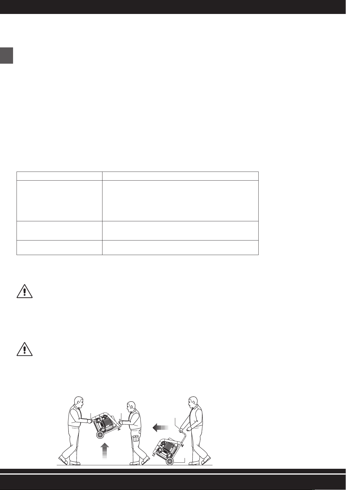
20
DE
10 - VERWENDUNGSBESCHRÄNKUNGEN
Diese Maschine wurde zur alleinigen Verwendung, wie in Abschnitt 9 beschrieben, entwickelt und produziert und jegliche andere Verwendung oder anderer Betrieb ist ausdrücklich untersagt,
um jederzeit die Sicherheit der verantwortlichen Bediener sowie die Effizienz der Maschine selbst sicherstellen zu können.
ES IST STRENGSTENS VERBOTEN DIE MASCHINE IN UMGEBUNGEN MIT POTENZIELL EXPLOSIVER ATHMOSPHÄRE UND/ODER IN GEGENWART VON BRENNBAREN DÄMPFEN IN
BETRIEB ZU NEHMEN (Z. B.: HOLZSTÄUBE, MEHLE, ZUCKER UND FUTTERMEHLE).
VERWENDUNGSBESCHRÄNKUNGEN: ES IST STRENGSTENS VERBOTEN DIE MASCHINE ZU UNSACHGEMÄSSEN ZWECKEN ZU VERWENDEN, DIE VOM BEABSICHTIGTEN VERWEND-
UNGSZWECK (ABSCHNITT 9) ABWEICHEN.
DIE MASCHINE IST AUSSERHALB DER REICHWEITE VON KINDERN ZU HALTEN.
WÄHREND DER VERWENDUNG IST ES UNBEDINGT ERFORDERLICH ZU ÜBERPRÜFEN, DASS KEINE NICHT AUTORISIERTEN PERSONEN IN DIE NÄHE DER MASCHINE GELANGEN.
ES IST STRENGSTENS VERBOTEN, LUFTSCHLÄUCHE (VERLÄNGERUNGEN), ANSCHLÜSSE UND WERKZEUGE ZU VERWENDEN, DIE NICHT GEEIGNET SIND UND/ODER NICHT DEN
GELTENDEN VORSCHRIFTEN ENTSPRECHEN.
ES IST STRENGSTENS VERBOTEN, DIE MASCHINE MIT KRANEN UND/ODER GABELSTAPLERN ANZUHEBEN.
ES IST STRENGSTENS VERBOTEN, DRUCKLUFTSTRÖME AUF PERSONEN, TIERE UND ANDERE DINGE ZU RICHTEN.
ES IST STRENGSTENS VERBOTEN, DIE MASCHINE ZUM TRANSPORT UND/ODER ANHEBEN VON PERSONEN, TIEREN UND ANDEREN DINGE ZU VERWENDEN.
ES IST STRENGSTENS VERBOTEN, AUF DIE MASCHINE ZU STEIGEN.
ES IST STRENGSTENS VERBOTEN, DIE MASCHINE DURCH WELCHE MITTEL UND/ODER FAHRZEUGE AUCH IMMER ZU SCHLEPPEN.
ES IST STRENGSTENS VERBOTEN, DIE MASCHINE MANUELL AUF STEIGUNGEN UND/ODER GEFÄLLEN MIT GEFÄHRLICHEM NEIGUNGSGRAD ZU BEWEGEN.
ES BESTEHT DIE GEFAHR VON VERBRENNUNGEN BEI VERSEHENTLICHEM KONTAKT MIT DER DOPPELZYLINDER-PUMPBAUGRUPPE UND DEM ELEKTROMOTOR. ACHTUNG! ES
BESTEHT IMMER EIN RESTRISIKO (SIEHE ABSCHNITT 21).
1 2
3
4
Abb. 3
7- GARANTIE
1) GARANTIEERKLÄRUNG: Der Hersteller garantiert gegenüber dem Käufer exklusiv den Austausch, die Reparatur oder anderweitige Maßnahmen an der Maschine, falls Konformitätsfehler
auftreten, die eine ordnungsgemäße Verwendung und den Betrieb gefährden würden, falls solche Defekte tatsächlich im Verantwortungsbereich des Herstellers liegen. Der Hersteller behält
sich das Recht vor, die beste Lösung zur Wiederherstellung der Ordnungsmäßigkeit der Maschine innerhalb eines vernünftigen Zeitraums zu wählen.
2) KÄUFER: Der Käufer wird als “Verbraucher” bezeichnet, wenn der Kauf von einer Einzelperson zu Zwecken ausgeführt wird, die nicht zu seinem/ihrem Geschäft oder der beruflichen
Aktivität gehört.
Der Käufer wird als “Profi oder Unternehmen” bezeichnet, wenn der Kauf von einer professionellen Person oder einem Unternehmen ausgeführt wird, dessen Handeln zu seinen/ihren
Geschäften oder beruflichen Aktivitäten gehört.
3) LAUFZEITEN: Der Hersteller haftet, wenn Fehler in der Konformität innerhalb der folgenden Zeiträume ab dem Kaufdatum auftreten
24 Monate, wenn der Kauf von einem “Verbraucher”, wie unter Punkt 2) beschrieben, durchgeführt wurde;
12 Monate, wenn der Kauf von einem “Profi oder Unternehmen”, wie unter Punkt 2) beschrieben, durchgeführt wurde;
4) GÜLTIGKEIT: Die Garantie ist gültig, wenn der Käufer den Hersteller über den Konformitätsfehler innerhalb von 2 Monaten nach dem Zeitpunkt benachrichtigt, zu dem ein solcher Fehler
zum ersten Mal bemerkt wurde. Solch eine Benachrichtigung muss zusammen mit einem gültigen Kaufdokument (Kassenzettel oder Rechnung) übermittelt werden.
5) ABLAUF: Die Garantie läuft ab, wenn der Käufer die Maschine unsachgemäß und/oder auf einer Art und Weise verwendet, die nicht mit den vom Hersteller bereitgestellten Bedienungs-
und Wartungsanweisungen übereinstimmt oder wenn der Konformitätsfehler aufgrund mangelnder Befähigung des Käufers oder per Zufall entstanden ist.
6) VERANTWORTLICHKEIT: Der Hersteller übernimmt keine Haftung für mögliche Folgeschäden der Käufer, die aus einem Verlust der Produktionsmöglichkeiten oder einer verringerten
Produktion aufgrund der Konformitätsfehler entstehen.
7) KOSTEN: Kosten in Verbindung mit Arbeit und Material, die zur Wiederherstellung der Konformität der Maschine erforderlich sind, gehen zu Lasten des Herstellers. Ausgaben und Liefer-
bedingungen müssen mit dem autorisierten Händler vereinbart werden.
8 - RECHTSVORBEHALT
Die im Rahmen der “Bedienungs- und Wartungsanweisungen” dieser Anleitung vorbehaltenen Rechte bleiben Eigentum des Herstellers. Kein Teil dieser Anleitung darf ohne schriftliche Gene-
hmigung des Herstellers durch welche Vervielfältigungsmittel auch immer reproduziert oder (gesamt oder teilweise) offengelegt werden. Alle genannten Warenzeichen gehören den jeweiligen
Eigentümern.
9 - VERWENDUNGSZWECK
VERWENDUNGSGEBIET Industrieller, gewerblicher und ziviler Sektor.
VERWENDUNGSORT
Innen- und Außenbereiche (vorausgesetzt es werden keine atmosphärischen Mittel aus-
gesetzt), die ausreichend beleuchtet und belüftet sind, sowie Werte für Lufttemperatur und
-feuchtigkeit aufweisen, die Abschnitt 2 entsprechen und im Rahmen der geltenden Gesetze
für Gesundheit und Sicherheit am Arbeitsplatz geeignet sind, an dem eine solche Verwend-
ung stattfinden soll. Die Maschine muss auf einer Oberfläche stehen, die die Stabilität im
Hinblick auf ihr Gewicht und die Gesamtabmessungen (siehe Abschnitt 2) sicherstellt.
ACHTUNG! DIE MASCHINE IST AUSSERHALB DER REICHWEITE VON KINDERN ZU HALTEN.
BEABSICHTIGTE VERWENDUNG
Kompression von Luft (ohne Öl) zur Verwendung von geeigneten pneumatischen Werkzeugen,
die den geltenden Gesetzen entsprechen. (z. B.: Düsen zum Strahlen, Lackieren oder
Sandstrahlen; Schrauber, Punktschweißgeräte, Niet- oder Schmiervorrichtungen).
MIT DER VERWENDUNG BEAUFTRAGTE
BEDIENER
Ein autorisierter Bediener, der die beruflichen Anforderungen aus Abschnitt 5 erfüllt.
This manual suits for next models
2
Table of contents
Languages:
Other Aerfast Air Compressor manuals


Popular Air Compressor manuals by other brands


Porter-Cable
Porter-Cable C2550 instruction manual

Hycomp
Hycomp Ambient Installation & operation manual

Aircraft
Aircraft AIRBOY 186 OF E operating instructions

Anest Iwata
Anest Iwata SLBE-7.5 instruction manual

California Air Tools
California Air Tools 10020C-22050 owner's manual

Wolf
Wolf Sioux 25 user guide


