Aerfast AC16006 User manual

Operating Manual
Mode d’Emploi
Betriebanleitung
Gebruikaanwijzing
Bruksanvisning
Käyttöohjeet ja osalista
Air Compressor, oil-less type
Compresseur d’air, modele sans huile
Kompressor, Typ - ölfrei
Compressor, Olieloos type
Luftkompressor, oljefritt utförande
Kompressorit, öljytön
AC16006, AC19003, AC24020, AC25420,
AC30419, AC30419-3PH, AC254100
AC24020
AC30419 / AC30419-3PH
AC19003
AC25420 AC254100
AC16006

GB
INSTRUCTION MANUAL AND SAFETY INSTRUCTION
reciprocating piston air compressor oil lubricated
F
D
MANUEL D’UTILISATION ET CONSIGNES DE SÉCURITÉ DU COMPRESSEUR
électrocompresseur à piston lubriés
BEDIENUNGS-UND WARTUNGSHANDBUCH
elecktrokompressoren mit geshmiertem kolben
NL
GEBRUIKS- EN ONDERHOUDSHANDBOEK
gesmeerde elektrocompressor met zuiger
SF
KÄYTTÖ- JA HUOLTO KÄSIKIRJA
rasvoitetut, männällä varustetut sähkökompressorit
S
BRUKSANVISNING OCH UNDERHÅLLSHANDBOK
elektriska kompressorer med smorda kolvar
G B
F
D
WARNING:
Please read understand this manual before
operating the compressor
AVVERTISSEMENT: Vauillez lire attentivement toutes les
instructions avant de mettre à la sécurité
HINWEIS:
Vor der Benutzung des Kompressors die im
S F VAROITUKSET: Lue tarkkaan tässä käsikirjassa annetut ohjeet
N L
vorliegenden Handbuch enthaltenen Anweisungen
aufmerksam lesen.
WAARSCHUWING:Lees voor het gebruik van de
S
ennen kompressorin käyttöä
VARNING:
Läs bruksanvisningens instruktioner noga innan du
använder kompressorn
compressor de aanwijzingen in dit handboek zorgvuldig door.
3
I LEGGERE IL LIBRETTO ISTRUZIONI
Prima di posizionare, mettere in funzione o intervenire sul compressore, leggere attentamente il libretto
istruzioni.
GB READ THE INSTRUCTION HANDBOOK
Before positioning, operating or adjusting the compressor, read the instruction handbook carefully.
F LIRE LE MANUEL D’INSTRUCTIONS
Avant de positionner, de mettre en service, ou d’intervenire sur le compresseur, lire attentivement le
manuel d’instructions.
D BETRIESANLEITUNG LESEN
Vor dem aufstellen, der Inbetriebnahme oder einem Eingriam Kompressor die Betriebsanleitung sorgfältig
lesen.
NL HET INSTRUCTIEBOEKJE LEZEN
Alvorens de compressor te plaatsen, in werking te stellen of erop tussen te komen, aandachtig het
instructieboekje lezen.
DK LÆS BRUGERVEJLEDNINGEN
Før anbringelse og start af kompressoren eller indgreb på denne, skal brugervejledningen læses grundigt.
E LEER EL MANUAL DE INSTRUCCIONES
Antes de posicionar, poner en función o intervenir en el compresor, leer atentamente el manual de
instrucciones.
P LER O MANUAL DE INSTRUÇÕES
Ler atentamente o manual de instruções antes de instalar, pôr em funcionamento ou intervir no compressor.
SF LUE KÄYTTÖOPAS
Ennen kompressorin asetusta, käynnistystä tai siihen muuten puuttumista lue huolella käyttöopas.
S LÄS BRUKSANVISNINGEN
Läs bruksanvisningen noga innan du installerar , använder eller utför underhållsarbete på kompressorn.
I RISCHIO DI SCOSSA ELETTRICA
Attenzione prima di eettuare ogni intervento sul compressore è obbligatorio disattivare l’alimentazione
elettrica sulla macchina stessa.
GB RISK OF ELECTRIC SHOCK
Caution: before doing any work on the compressor it must be disconnected from the power supply.
F RISQUE DE DECHARGE ELECTRIQUE
Attention, avant d’eectuer toute intervention sur le compresseur, il est obligatore de désactiver l’alimentation
électrique de la machine.
D GEFÄHRDUNG DURCH STROMSCHLAG
Achtung! Bevor ein Eingri am Kompressor durchgeführt wird, muss die Stromzufuhr auf der Machine
unterbrochen werden.
NL RISICO VAN ELEKTRISCHE SCHOK
Alvorens eender welke handeling uit te voeren op de compressor is het verplicht de elektrische stroom op
de machine zelf uit te schakelen.
DK FARE FOR ELEKTRISK STØD
Pas på: før et eventuelt indgreb på kompressoren skal denne afkobles fra elforsyningnettet.
E RIESGO DE CHOQUE ELECTRICO
¡Cuidado!Antes de efectuar cualquier intervención en el compresor, es obligatorio desconectar la
alimentación eléctrica de la misma máquina.
P PERIGO DE CHOQUE ELÉCTRICO
Atenção, é obrigatório desligar a alimentação eléctrica da máquina antes de efectuar qualquer intervenção
no compressor.
SF SÄHKÖISKUN VAARA
Ennen mitä tahansa koneeseen puuttumista sähkönsyöttö koneeseen pitää kytkeä irti.
S RISK FÖR ELEKTRISK STÖT
Varning! Innan du utför underhållsarbete på kompressorn, måste du koppla från strömtillförseln till maskinen.
> 70 db
4
I RISCHIO DI TEMPERATURE ELEVATE
Attenzione nel compressore ci sono alcune parti che protrebbero raggiungere temperature elevate.
GB RISK OF HIGH TEMPERATURES
Caution: the compressor contains some parts which might reach high temperatures.
F RISQUE DE TEMPERATURE ELEVEES
Attention, à l’interieur du compresseur se trouvent des certaines pièces susceptibles d’atteindre des
températures élevées.
D GEFÄHRDUNG DURCH HOHE TEMPERATUREN
Achtung! Der Kompressor enthält Bauteile, die sich stark erhitzen können.
NL RISICO VAN HOGE TEMPERATUREN
Opgelet op de compressor zijn er enkele delen die zeer hoge temperaturen zouden kunnen bereiken.
DK RISIKO FOR HØJE TEMPERATURER
Pas på: kompressoren indeholder dele, der kan nå meget høje temperaturer.
E RIESGO DE TEMPERATURAS ELEVADAS
¡Cuidado! En el compresor algunas partes podrían alcanzar temperaturas elevadas.
P PERIGO DE TEMPERATURAS ELEVADAS
Antenção, no compressor existem algumas partes que poderão atingir temperaturas elevadas.
SF KORKEAN LÄMPÖTILAN VAARA
Huomio: kompressorissa on osia, jokta voivat kuumettua huomattavasti.
S RISK FÖR HÖG TEMPERATUR
Varning! Inuti kompressorn nns det vissa delar som kan uppnå mycket hög temperatur.
I RISCHIO DI PARTENZA ACCIDENTALE
Attenzione il compressore potrebbe ripartire in caso di black-out e successivo ripristino di tensione.
GB RISK OF ACCIDENTAL START-UP
Attention, the compressor could start automatically in case of a black-out and subsequent reset.
F RISQUE DE DEPART ACCIDENTEL
Attention: le compresseur est susceptible de redemarrer automatiquement en cas de black-out et
retablissement successif de la tension.
D GEFÄHR EINES UNVORHERGESEHENEN STARTS
Achtung! Der Kompressor könnte bei einem stromausfall nach rückkehr des stroms automatisch neustarten.
NL ONGEWENST STARTGEVAAR
Let op, de compressor kan bij stroomuitval en daaropvolgend stroomherstel automatisch van start gaan.
DK RISIKO FOR TILFÆLDIG START
Pas på: kompressoren kan starte automatisck igen i tilfælde af black-out med efterfølgende genoptagelse
af den elektriske spænding.
E PELIGRO DE ARRANQUE ACCIDENTAL
¡Atencion! El compresor puede volver a arrancar automáticamente en caso de interrupción generalizada
de la corriente y tras haber restablecido la coriente.
P PERIGO DE ARRANQUE ACIDENTAL
Antenção, o compressor pode arrancar automaticamente depois de uma falha de corrente eléctrica e
sucessiva ligação da mesma.
SF TAHATTOMAN KÄYNNISTYMISEN VAARA
Huomio: kompressori saattaa käynnistyä uudelleen au tomaattisesti virran palatessa sähkökatkon jälkeen.
S RISK FÖR OFRIVILLIG START
Varning! kompressorn kan återstarta automatiskt då strömmen återställs efter ett strömavbrott.
Recycling!

5
! #"
$ %
& '
!
6
14 15 16 17
18 19
20 21
22 23
24 25

7
$ %
& '
' ')
!
!
!)
!
! !!
!!)
!" !#
8
!$ !%

9
GM 203
SILENT AB
1
2
3
4
5
1
2
3
5
4
SILENT VX
1
5
2
3
4

10
9
10
11
8
12
1
7
6
5
4
32
GM
7
6
5
4
3
2
8
9
10
11
13
14 12
VX

12
MOD. GM
1. SERBATOIO / TANK / RESERVOIR / KESSEL / TANK / BEHOLDER / DEPÓSITO /DEPÓSITO /SÄILIÖ /TANK
2. SCARICO CONDENSA /CONDENSATE DRAIN /EVACUATION CONDENSATION /AUSLASS KONDENSWASSER /AFVOER CONDENSWATER /
TØMNING AF KONDENSVAND /DESAGÜE DEL CONDENSADO /PURGA DA CONDENSAÇÃO /KONDENSSIVEDEN TYHJENNYS /
KONDENSVATTNETS AVLOPP
3. RUOTA /WHEEL /ROUE /RAD /WIEL /HJUL /RUEDA /RODA /PYÖRÄ /HJUL
4. GRUPPO COMPRESSORE /COMPRESSOR UNIT /GROUPE COMPRESSEUR /KOMPRESSORAGGREGAT /COMPRESSOR GROEP /
KOMPRESSORENHED /GRUPO COMPRESOR /GRUPO COMPRESSOR /KOMPRESSORIYKSIKKÖ /KOMPRESSORGRUPP
5. ASTA LIVELLO OLIO /OIL LEVEL STICK /TIGE DE NIVEAU D’HUILE /ÖLSTAB /STOK OLIENIVEAU /OLIEMÅLEPIND /VARILLA NIVEL DE ACEITE /
VARETA NÍVEL ÓLEO /ÖLJYTASOTANKO /OLJEMÄTSTICKA
6. FILTRO ARIA /AIR FILTER /FILTRE A AIR /LUFTFILTER /LUCHTFILTER /LUFTFILTER /FILTRO DE AIRE /FILTRO AR /ILMASUODATIN /
LUFTFILTER
7. CARENATURA DI PROTEZIONE /GUARD /CARENAGE DE PROTECTION /SCHUTZVERKLEIDUNG /BESCHERMINGSSTROOMLIJNKAP /
STRØMLINIEBEKLÆDNING /CARENADURA DE PROTECCIÓN /COBERTURA DE PROTECÇÃO /SUOJUS /SKYDDSBEKLÄDNAD
8. PRESSOSTATO /PRESSURE SWITCH /PRESSOSTAT /DRUCKWÄCHTER /DRUKREGELAAR /PRESSOSTAT /PRESOSTATO /BARÓSTATO /
PAINEMITTARI /TYCKMÄTARE
9. RIDUTTORE DI PRESSIONE /PRESSURE REDUCER /REDUCTEUR DE PRESSION /DRUCKMINDERER /DRUKREDUCTIEMACHINE /
TRYKBEGRÆNSER /REDUCTOR DE PRESIÓN /REDUTOR DE PRESSÃO /PAINEENVÄHENTÄJÄ /TYCKREDUCERARE
10. MANICO /HANDLE /POIGNEE /SCHLAUCH /HANDVAT /HANK /MANIJA /ASA /KAHVA /HANDTAG
11. USCITA ARIA COMPRESSA /COMPRESSED AIR OUTLET /SORTIE AIR COMPRIME /DRUCKLUFTAUSGANG /UITGANG SAMENGEPERSTE LUCHT
/UDGANG FOR TRYKLUFT /SALIDA DEL AIRE COMPRIMIDO /SAIDA AR COMPRIMIDO /PAINEILMAN ULOSOMENO /TRYCKLUFTSUTGÅNG
12. VALVOLA DI SICUREZZA /SECURITY VALVE /VANNE DE SECURITE /SICHERHEITSVENTIL /VEILIGHEIDSKLEP /SIKKERHEDSVENTIL /VALVULA
DE SEGURIDAD /VALVULA DE SEGURANCA /PAINEENALENNENNUSVENTTIILI /SÄKERHETSVENTIL
MOD. VX
1. SERBATOIO / TANK / RESERVOIR / KESSEL / TANK / BEHOLDER / DEPÓSITO /DEPÓSITO /SÄILIÖ /TANK
2. MANOMETRO /PRESSURE GAUCE /MANOMETRE /MANOMETER /MANOMETER /TRYKMÅLER /MANÓMETRO /MANÓMETRO /MANOMETRI /
MANOMETER
3. PRESSOSTATO /PRESSURE SWITCH /PRESSOSTAT /DRUCKWÄCHTER /DRUKREGELAAR /PRESSOSTAT /PRESOSTATO /BARÓSTATO /
PAINEMITTARI /TYCKMÄTARE
4. MANICO /HANDLE /POIGNEE /SCHLAUCH /HANDVAT /HANK /MANIJA /ASA /KAHVA /HANDTAG
5. CARENATURA DI PROTEZIONE /GUARD /CARENAGE DE PROTECTION /SCHUTZVERKLEIDUNG /BESCHERMINGSSTROOMLIJNKAP /
STRØMLINIEBEKLÆDNING /CARENADURA DE PROTECCIÓN /COBERTURA DE PROTECÇÃO /SUOJUS /SKYDDSBEKLÄDNAD
6. GRUPPO COMPRESSORE /COMPRESSOR UNIT /GROUPE COMPRESSEUR /KOMPRESSORAGGREGAT /COMPRESSOR GROEP /
KOMPRESSORENHED /GRUPO COMPRESOR /GRUPO COMPRESSOR /KOMPRESSORIYKSIKKÖ /KOMPRESSORGRUPP
7. FILTRI ARIA /AIR FILTER /FILTRE A AIR /LUFTFILTER /LUCHTFILTER /LUFTFILTER /FILTRO DE AIRE /FILTRO AR /ILMASUODATIN /
LUFTFILTER
8. ASTA LIVELLO OLIO /OIL LEVEL STICK /TIGE DE NIVEAU D’HUILE /ÖLSTAB /STOK OLIENIVEAU /OLIEMÅLEPIND /VARILLA NIVEL DE ACEITE /
VARETA NÍVEL ÓLEO /ÖLJYTASOTANKO /OLJEMÄTSTICKA
9. USCITA ARIA COMPRESSA RIDOTTA /REDUCED COMPRESSED AIR OUTLET /SORTIE RÉDUITE AIR COMPRIMÉ /REDUZIERTE
DRUCKLUFTAUSGANG /UITGANG SAMENGEPERSTE LUCHT VERMINDERD /UDGANG FOR REDUCERET TRYKLUFT /SALIDA DEL AIRE
COMPRIMIDO REDUCIDA /SAÍDA AR COMPRIMIDO REDUZIDA /PAINEILMAN VÄHENNETTY ULOSMENO /REDUCERAD TRYCKLUFTSUTGÅNG
10. RIDUTTORE DI PRESSIONE /PRESSURE REDUCER /REDUCTEUR DE PRESSION /DRUCKMINDERER /DRUKREDUCTIEMACHINE /
TRYKBEGRÆNSER /REDUCTOR DE PRESIÓN /REDUTOR DE PRESSÃO /PAINEENVÄHENTÄJÄ /TYCKREDUCERARE
11. USCITA ARIA COMPRESSA DIRETTA /DIRECT COMPRESSED AIR OUTLET /SORTIE DIRECTE AIR COMPRIMÉ /DIREKTER DRUCKLUFTAUSGANG
/UITGANG SAMENGEPERSTE LUCHT DIRECT /UDGANG FOR DIREKTE LUFTTRYK /SALIDA DEL AIRE COMPRIMIDO DIRECTA /SAÍDA AR
COMPRIMIDO DIRECTA /PAINEILMAN SUORA ULOSMENO /DIREKT TRYCKLUFTSUTGÅNG
12. RUOTA /WHEEL /ROUE /RAD /WIEL /HJUL /RUEDA /RODA /PYÖRÄ /HJUL
13. VALVOLA DI NON RITORNO /CHECK VALVE /VANNE DE NON-RETOUR /RÜCKSCHLAGVENTIL /KLEP VOOR NIET TERUGKEER /KONTRAVENTIL
/VÁLVULA DE ANTIRRETROCESO /VÁLVULA DE NÃO RETORNO /TAKAISKUVENTTIILI /VENTIL UTAN ÅTERGÅNG
14. SCARICO CONDENSA /CONDENSATE DRAIN /EVACUATION CONDENSATION /AUSLASS KONDENSWASSER /AFVOER CONDENSWATER /
TØMNING AF KONDENSVAND /DESAGÜE DEL CONDENSADO /PURGA DA CONDENSAÇÃO /KONDENSSIVEDEN TYHJENNYS /
KONDENSVATTNETS AVLOPP
MOD. SILENT (AB e VX)
1. CARENATURA DI PROTEZIONE /GUARD /CARENAGE DE PROTECTION /SCHUTZVERKLEIDUNG /BESCHERMINGSSTROOMLIJNKAP /
STRØMLINIEBEKLÆDNING /CARENADURA DE PROTECCIÓN /COBERTURA DE PROTECÇÃO /SUOJUS /SKYDDSBEKLÄDNAD
2. VALVOLA DI SICUREZZA /SECURITY VALVE /VANNE DE SECURITE /SICHERHEITSVENTIL /VEILIGHEIDSKLEP /SIKKERHEDSVENTIL /VALVULA
DE SEGURIDAD /VALVULA DE SEGURANCA /PAINEENALENNENNUSVENTTIILI /SÄKERHETSVENTIL
3. USCITA ARIA COMPRESSA DIRETTA /DIRECT COMPRESSED AIR OUTLET /SORTIE DIRECTE AIR COMPRIMÉ /DIREKTER DRUCKLUFTAUSGANG
/UITGANG SAMENGEPERSTE LUCHT DIRECT /UDGANG FOR DIREKTE LUFTTRYK /SALIDA DEL AIRE COMPRIMIDO DIRECTA /SAÍDA AR
COMPRIMIDO DIRECTA /PAINEILMAN SUORA ULOSMENO /DIREKT TRYCKLUFTSUTGÅNG
4. PRESSOSTATO /PRESSURE SWITCH /PRESSOSTAT /DRUCKWÄCHTER /DRUKREGELAAR /PRESSOSTAT /PRESOSTATO /BARÓSTATO /
PAINEMITTARI /TYCKMÄTARE
5. SERBATOIO / TANK / RESERVOIR / KESSEL / TANK / BEHOLDER / DEPÓSITO /DEPÓSITO /SÄILIÖ /TANK

13
MOD. GM 203
1. CARENATURA DI PROTEZIONE /GUARD /CARENAGE DE PROTECTION /SCHUTZVERKLEIDUNG /BESCHERMINGSSTROOMLIJNKAP /
STRØMLINIEBEKLÆDNING /CARENADURA DE PROTECCIÓN /COBERTURA DE PROTECÇÃO /SUOJUS /SKYDDSBEKLÄDNAD
2. TAPPO SFIATO OLIO /BREATHER PLUG /BOUCHON DE PURGE /ENTLUFTUNGSSTOPFEN /VENTILPROP /TAPON DE PURGA /TAMPAO DE
PURGA /ILMATULPPAAN /LUFTHAL
3. MANICO /HANDLE /POIGNEE /SCHLAUCH /HANDVAT /HANK /MANIJA /ASA /KAHVA /HANDTAG
4. PRESSOSTATO /PRESSURE SWITCH /PRESSOSTAT /DRUCKWÄCHTER /DRUKREGELAAR /PRESSOSTAT /PRESOSTATO /BARÓSTATO /
PAINEMITTARI /TYCKMÄTARE
5. RUOTA /WHEEL /ROUE /RAD /WIEL /HJUL /RUEDA /RODA /PYÖRÄ /HJUL
6. SERBATOIO / TANK / RESERVOIR / KESSEL / TANK / BEHOLDER / DEPÓSITO /DEPÓSITO /SÄILIÖ /TANK
MOD. AB - MOD. CCS
1. USCITA ARIA COMPRESSA DIRETTA /DIRECT COMPRESSED AIR OUTLET /SORTIE DIRECTE AIR COMPRIMÉ /DIREKTER DRUCKLUFTAUSGANG
/UITGANG SAMENGEPERSTE LUCHT DIRECT /UDGANG FOR DIREKTE LUFTTRYK /SALIDA DEL AIRE COMPRIMIDO DIRECTA /SAÍDA AR
COMPRIMIDO DIRECTA /PAINEILMAN SUORA ULOSMENO /DIREKT TRYCKLUFTSUTGÅNG
2. SERBATOIO / TANK / RESERVOIR / KESSEL / TANK / BEHOLDER / DEPÓSITO /DEPÓSITO /SÄILIÖ /TANK
3. RIDUTTORE DI PRESSIONE /PRESSURE REDUCER /REDUCTEUR DE PRESSION /DRUCKMINDERER /DRUKREDUCTIEMACHINE /
TRYKBEGRÆNSER /REDUCTOR DE PRESIÓN /REDUTOR DE PRESSÃO /PAINEENVÄHENTÄJÄ /TYCKREDUCERARE
4. PARACINGHIA /BELT-GUARD /PROTECTION COURROIE /RIEMENSCHUTZ /KETTINGBESCHERMER /BESKYTTELSESSKÆRM FOR REM /
CUBRECORREA /PROTECÇÃO DA CORREIA /HIHNASUOJUS /REMSKYDD
5. GRUPPO COMPRESSORE /COMPRESSOR UNIT /GROUPE COMPRESSEUR /KOMPRESSORAGGREGAT /COMPRESSOR GROEP /
KOMPRESSORENHED /GRUPO COMPRESOR /GRUPO COMPRESSOR /KOMPRESSORIYKSIKKÖ /KOMPRESSORGRUPP
6. MOTORE ELETTRICO /ELECTRIC MOTOR /MOTEUR ÉLECTRIQUE /ELEKTROMOTOR /ELEKTRISCHE MOTOR /ELEKTRISK MOTOR /MOTOR
ELÉCTRICO /MOTOR ELÉCTRICO /SÄHKÖMOOTTORI /ELMOTOR
7. PRESSOSTATO /PRESSURE SWITCH /PRESSOSTAT /DRUCKWÄCHTER /DRUKREGELAAR /PRESSOSTAT /PRESOSTATO /BARÓSTATO /
PAINEMITTARI /TYCKMÄTARE
8. MANOMETRO /PRESSURE GAUCE /MANOMETRE /MANOMETER /MANOMETER /TRYKMÅLER /MANÓMETRO /MANÓMETRO /MANOMETRI /
MANOMETER
9. RUOTA PIVOTTANTE /PIVOT WHEEL /ROUE PIVOTANTE /SCHWENKRAD /DRAAIEND WIEL /HJULTAP /RUEDA PIVOTANTE /RODA GIRATÓRIA
/KÄÄNTÖPYÖRÄ /ROTERANDE HJUL
10. SCARICO CONDENSA /CONDENSATE DRAIN /EVACUATION CONDENSATION /AUSLASS KONDENSWASSER /AFVOER CONDENSWATER /
TØMNING AF KONDENSVAND /DESAGÜE DEL CONDENSADO /PURGA DA CONDENSAÇÃO /KONDENSSIVEDEN TYHJENNYS /
KONDENSVATTNETS AVLOPP
11. RUOTA /WHEEL /ROUE /RAD /WIEL /HJUL /RUEDA /RODA /PYÖRÄ /HJUL
12. VALVOLA DI RITEGNO /CHECK VALVE /VANNE DE RETENNE /RÜCKSCHLAGVENTIL /TEGENHOUDKLEP /KONTRAVENTIL /VÁLVULA DE
RETENCIÓN /VÁLVULA DE RETENÇÃO /TAKAISKUVENTTIILI /STOPPVENTIL
MOD. ABT
1. SERBATOIO / TANK / RESERVOIR / KESSEL / TANK / BEHOLDER / DEPÓSITO /DEPÓSITO /SÄILIÖ /TANK
2. MOTORE ELETTRICO N. 1 /ELECTRIC MOTOR N. 1 /MOTEUR ÉLECTRIQUE N. 1 /ELEKTROMOTOR NR. 1 /ELEKTRISCHE MOTOR N. 1 /
ELEKTRISK MOTOR NR.1 /MOTOR ELÉCTRICO N.1 /MOTOR ELÉCTRICO Nº 1 /SÄHKÖMOOTTORI N: 1 /ELMOTOR NR. 1
3. PARACINGHIA /BELT-GUARD /PROTECTION COURROIE /RIEMENSCHUTZ /KETTINGBESCHERMER /BESKYTTELSESSKÆRM FOR REM /
CUBRECORREA /PROTECÇÃO DA CORREIA /HIHNASUOJUS /REMSKYDD
4. GRUPPO COMPRESSORE N. 1 /COMPRESSOR UNIT N. 1 /GROUPE COMPRESSEUR N. 1 /KOMPRESSORAGGREGAT NR. 1 /COMPRESSOR
GROEP N. 2 /KOMPRESSORENHED NR. 1 /GRUPO COMPRESOR N. 1 /GRUPO COMPRESSOR Nº 1 /KOMPRESSORIYKSIKKÖ N: 1 /
KOMPRESSORGRUPP NR. 1
5. GRUPPO COMPRESSORE N. 2 /COMPRESSOR UNIT N. 2 /GROUPE COMPRESSEUR N. 2 /KOMPRESSORAGGREGAT NR. 2 /COMPRESSOR
GROEP N. 2 /KOMPRESSORENHED NR. 2 /GRUPO COMPRESOR N. 2 /GRUPO COMPRESSOR Nº 2 /KOMPRESSORIYKSIKKÖ N: 2 /
KOMPRESSORGRUPP NR. 2
6. MOTORE ELETTRICO N. 2 /ELECTRIC MOTOR N. 2 /MOTEUR ÉLECTRIQUE N. 2 /ELEKTROMOTOR NR. 2 /ELEKTRISCHE MOTOR N. 2 /
ELEKTRISK MOTOR NR. 2 /MOTOR ELÉCTRICO N. 2 /MOTOR ELÉCTRICO Nº 2 /SÄHKÖMOOTTORI N: 2 /ELMOTOR NR. 2
7. CENTRALIANA AVVIAMENTO YD /STARTING CONTROL UNIT YD /BOÎTIER DE DÉMARRAGE Y? /STERNDREIECKANLASSER /CENTRALE
OPSTARTEN UD /ELEKTRONISK BETJENINGSPANEL FOR START YD /CENTRAL DE PUESTA EN MARCHA YD /CAIXA DE ARRANQUE YD /
KÄYNNISTYS VAIHDELAATIKKO YD /STARTCENTRAL YD
8. USCITA ARIA COMPRESSA DIRETTA /DIRECT COMPRESSED AIR OUTLET /SORTIE DIRECTE AIR COMPRIMÉ /DIREKTER DRUCKLUFTAUSGANG
/UITGANG SAMENGEPERSTE LUCHT DIRECT /UDGANG FOR DIREKTE LUFTTRYK /SALIDA DEL AIRE COMPRIMIDO DIRECTA /SAÍDA AR
COMPRIMIDO DIRECTA /PAINEILMAN SUORA ULOSMENO /DIREKT TRYCKLUFTSUTGÅNG
9. PRESSOSTATO /PRESSURE SWITCH /PRESSOSTAT /DRUCKWÄCHTER /DRUKREGELAAR /PRESSOSTAT /PRESOSTATO /BARÓSTATO /
PAINEMITTARI /TYCKMÄTARE
10. MANOMETRO /PRESSURE GAUCE /MANOMETRE /MANOMETER /MANOMETER /TRYKMÅLER /MANÓMETRO /MANÓMETRO /MANOMETRI /
MANOMETER
11. SCARICO CONDENSA /CONDENSATE DRAIN /EVACUATION CONDENSATION /AUSLASS KONDENSWASSER /AFVOER CONDENSWATER /
TØMNING AF KONDENSVAND /DESAGÜE DEL CONDENSADO /PURGA DA CONDENSAÇÃO /KONDENSSIVEDEN TYHJENNYS /
KONDENSVATTNETS AVLOPP

GB 14
IMPORTANT INFORMATION
Read and understand all of the operating instructions, safety precautions
and warnings in the Instruction Manual before operating or maintaining
this compressor.
Most accidents that result from compressor operation and maintenance
are caused by the failure to observe basic safety rules or precautions.
An accident can often be avoided by recognizing a potentially hazardous
situation before it occurs, and by observing appropriate safety
procedures.
Basic safety precautions are outlined in the “SAFETY” section of this
Instruction Manual nad in the sections which contain the operation and
maintenance instructions.
Hazards that must be avoided to prevent bodily injury or machine damage
are identified by WARNINGS on the compressor and in this Instruction
Manual.
Never use this compressor in a manner that has not been specifically
recommended by manufacturer, unless you first confirm that the planned
use will be safe for you and others.
MEANINGS OF SIGNAL WORDS
WARNING: indicates a potentially hazardous situations which, if ignored,
could result in serious personal injury.
CAUTION: indicates a hazardous situations which, if ignored, couls result
moderate personal injury, or could cause machine damage.
NOTE: emphasizes essential information
SAFETY
IMPORTANT SAFETY INSTRUCTIONS FOR USE
OF THE COMPRESSOR.
WARNING:
DEATH OR SERIOUS BODILY INJURY COULD RESULT FROM
IMPROPER OR UNSAFE USE OF COMPRESSOR. TO AVOID
THESE RISKS, FOLLOW THESE BASIC SAFETY INSTRUCTIONS.
READ ALL INSTRUCTIONS
1. NEVER TOUCH MOVING PARTS
Never place your hands, fingers or other body parts near the
compressor’s moving parts.
2. NEVER OPERATE WITHOUT ALL GUARDS IN PLACE
Never operate this compressor without all guards or safety features
in place and in proper working order. If maintenance or servicing
requires the removal of a guard or safety features, be sure to replace
the guards or safety feature before resuming operation of the
compressor.
3. ALWAYS WEAR EYE PROTECTION
Always wear safety goggles or equivalent eye protection.
Compressed air must never be aimed at anyone or any part of the
body.
4. PROTECT YOURSELF AGAINST ELECTRIC SHOCK
Prevent body contact with grounded surfaces such as pipes,
radiators, ranges and refrigeration enclosures. Never operate the
compressor in damp or wet locations.
5. DISCONNECT THE COMPRESSOR
Always disconnect the compressor from the power source and
remove the compressed air from the air tank before servicing,
inspecting, maintaining, cleaning, replacing or checking any parts.
6. AVOID UNINTENTIONAL STARTING
Do not carry the compressor while it is connected to its power source
or when the air tank is filled with compressed air. Be sure the knob
of the pressure switch in the “OFF” position before connecting the
compressor to its power source.
7. STORE COMPRESSOR PROPERLY
When not in use, the compressor should be stored in dry place.
Keep out of reach of children. Lock-out the storage area.
8. KEEP WORK AREA CLEAN
Cluttered areas invite injurues. Clear all work areas of unnecessary
tools, debris, furniture etc…
9. KEEP CHILDREN AWAY
Do not let visitors contact compressor extension cord. Alla visitors
should be kept safely away from work area.
10. DRESS PROPERLY
Do not wear loose clothing or jewerly. They can be caught in moving
parts. Wear protective hair covering to contain long hair.
11. DON’T ABUSE CORD
Never yank it to disconnect from receptable. Keep cord from heat,
oil and sharp edges.
12. MAINTAIN COMPRESSOR WITH CARE
Follow instructions for lubricating. Inspect cords periodically and if
damaged, have repaired by authorized service facility.
Inspect extension cords periodically and replace if damaged.
13. OUTDOOR USE EXTENSION CORDS
When compressor in used outdoors, use only extension cords
intended for use outdoors and so marked.
14. STAY ALERT
Watch what you are doing. Use common sense. Do not operate
compressor when you are tired.
Compressor should never be used by you if you are under the influence
of alcohol, drugs or medication that makes you drowsy.
15. CHECK DAMAGED PARTS AND AIR LEAK
Before further use of the compressor, a guard or other part is
damaged should be carefully checked to determine that it will operate
properly and perform its intended function.
Check for alignment of moving parts, binding of moving parts,
breakage of parts, mounting, air leak, and any other conditions that
may affect its operation.
A guard or other part that is damaged should be properly repaired
or replaced by an authorized service center unless otherwise
indicated elsewhere in this Instruction Manual. Have defective
pressure switches replaced by authorized service center.
Do not use compressor if switch does not turn it on and off.
16. HANDLE COMPRESSOR CORRECTLY
Operate the compressor according to the instructions provided
herein. Never allow the compressor to be operated by children,
individuals unfamiliar with its operation or unauthorized personnel.
17. KEEP ALL SCREWS, BOLTS AND COVERS TIGHTLY IN PLACE
Keep all screws, bolts, and plates tightly mounted.
Check their condtions periodically.
18. KEEP MOTOR AIR VENT CLEAN
The motor air vent must be kept clean so that air can freely flow at
all times. Check for dust build-up frequently.
19. OPERATE COMPRESSOR AT THE RATED VOLTAGE
Operate the compressor at voltages specified on their nameplates.
If using the compressor at a higher voltage than the rated voltage, it
will result in abnormally fast motor revolution and mey damage the
unit and burn out the motor.
20. NEVER USE A COMPRESSOR WHICH IS DEFECTIVE OR
OPERATING ABNORMALLY
If the compressor appears to be operating unusually, making strange
noises, or otherwise appears defective, stop using it immediately
and arrange for repairs by a authorized service center.
21. DO NOT WIPE PLASTIC PARTS WITH SOLVENT
Solvents such as gasoline, thinner, benzine, carbon tetrachloride,
and alcohol may damage and crack plastic parts. Do not wipe them
with such solvents. Wipe plastic parts with a soft cloth lightly

15GB
dampened with soapy water and dry thoroughly.
22. USE ONLY GENUINE REPLACEMENT PARTS
Replacement parts not original may void your warranty and can lead
to malfunction and resulting injuries. Genuine parts are available
from your dealer.
23. DO NOT MODIFY THE COMPRESSOR
Do not modify the compressor.Always contact the authorized service
center any repairs. Unauthorized modification may not only impair
the compressor performance but may also result in accident or injury
to repair personnel who do not have the required knowledge and
technical expertise to perform the repair operations correctly.
24. TURN OFF THE PRESSURE SWITCH WHEN THE COMPRESSOR
IS NOT USED
When the compressor is not used, turn the knob of the pressure
switch OFF, disconnect it from the power source and open the drain
cock to discharge the compressed air from the air tank.
25. NEVER TOUCH HOT SURFACE
To reduce the risk of burns, do not touch tubes, heads, cylinder and
motors.
26. DO NOT DIRECT AIR STREAM AT BODY
Risk of injury, do not direct air stream at persons or animals.
27. DRAIN TANK
Drain tank daily or after 4 hours of use.
Open drain fitting and tilt compressor to empty accumulated water.
28. DO NOT STOP COMPRESSOR BY PULLING OUT THE PLUG
Use the “AUTO/OFF” knob of pressure switch.
29. USE ONLY RECOMMENDED AIR HANDLING PARTS
ACCEPTABLE FOR PRESSURE NOT LESS THAN 125 PSI (8.6
BAR)
Risk of bursting. Use only recommended air handling parts
acceptable for pressures not less than 125 psi (8.6 bar).
REPLACEMENT PARTS
When servicing use only identical replacement parts.
Repairs should be conducted only by authorized service center.
SAFETY - continued
GROUNDING INSTRUCTIONS
This compressor should be grounded while in use to protect the operator
from electric shock. The compressor is equipped with a three-conductor
cord and three-prong grounding type plug to fit the proper grounding
type receptacle.
The green (or green and yellow) conductor in the cord is the grounding
wire. Never connect the green (or green and yellow) wire to a live terminal.
If your units is for use on less than 150 volts, it has a plug that looks like
that shown in sketch (A) in figure on the right. An adapter, see sketches
(B) and (C), is available for connecting sketch (A) type plugs to two-
prong receptacles. The green-colored rigid ear, lug, or the like extending
from the adapter must be connected to a permanent ground, such as a
properly grounded outlet box.
NOTE: the grounding adaptor, sketch (C), is prohibited in Canada by
Canadian Electrical Code Part.1. Therefore, the instructions for its use
are not applicable in Canada.
EXTENSION CORD
Use only three-extension cords that have three-prong grounding type
plugs and three-pole receptables that accept the compressor’s plug.
Replace or repair damaged cord. Make sure your extension cord is in
good condition. When using an extension cord, be sure to use one heavy
enough to carry the current your product will draw. An undersized cord
will cause a drop in line voltage resulting in loss of power and overheating.
Table shows the correct size to use depending on cord lenght and name
plate ampere rating. If in doubt, use the next heavier gage. The smaller
the gage number, the heavier the cord.
Tab.1
SECTION VALID FOR A MAX LENGHT OF 20 mt single-phase
CV kW 220/230V 110/120V
mm
2
mm
2
0.75 – 1 0.65 – 0.7 1.5 2.5
1.5 1.1 2.5 4
2 1.5 2.5 4 –6
2.5 – 3 1.8 – 2.2 4 /
The diameter of the extension cable of the 3-phase compressors must
be in proportion to its length: see table (tab 2)
Tab. 2
SECTION VALID FOR A MAX LENGHT OF 20 mt three-phase
CV kW 220/230V 380/400V
mm
2
mm
2
2 – 3 – 4 1.5 – 2.2 – 3 2.5 1.5
5.5 4 4 2
7.5 5.5 6 2.5
10 7.5 10 4
WARNING
Avoid electrical shock hazard. Never use this compressor with a
damaged or frayed electrical cord or extension cord. Inspect all electrical
cords regularly. Never use in near water or in any environment where
electric shock is possible
SAVE THESE INSTRUCTION AND
MAKE THEM AVAILABLE TO OTHER USERS OF THIS TOOL!
OPERATION AND MAINTENANCE
NOTE: The information contained in this Instruction Manual is designed
to assist you in the safe operation and maintenance of the compressor.
Some illustrations in this Instruction Manual may show details or
attachments that differ from those on your own compressor.
INSTALLATION
Remove the compressor from its packing (fig.1), makes sure it is in
perfect condition, checking if it was damaged during transport, and carry
out the following operations. Fit the wheels and rubber tab on the tanks
on which they are not already fitted, observing the instructions in fig.2.
In case of infiatable wheels, the maximum inflation pressure must be of
1,6 bar (24 psi). Position the compressor on a flat surface or with a
maximum permissible inclination of 10°(fig. 3), in a well aired place,
protected against atmospheric agents and not in a place subject to
explosion hazard. If the surface is inclined and smooth, check if the
compressor moves while in operation – if it does, secure the wheels
with two wedges. If the surface is a bracket or a shelf top, make sure it
cannot fall, securing it in a suitable way. To ensure good ventilation and
efficient cooling, the compressor’s belt guard must be at least 100 cm
from any wall (fig. 4). Compressors fitted on the tank, with fixed feet,
should not be rigidly secured to the ground. In this case, we advise you
to fit 4 anti-vibration supports.
USE INSTRUCTIONS
– Take care to transport the compressor correctly, do not overturn it or
lift it with hooks or ropes (fig. 5 - 6)
– Replace the plastic plug on the guard cover (fig. 7 - 8) with the oil
level stick (fig. 9) or with the relevant breather plug (fig. 10), supplied
with the instructions booklet. Check oil level, consulting the reference
marks on the stick (fig. 9) or the oil level inspection window (fig. 11).

GB 16
ELECTRICAL CONNECTION
Single-phase compressors are supplied with an electrical cable and a
two-pole + earth plug. The compressor must be connected to a grounded
power socket (fig.12).
Three-phase compressors (L1+L2+L3+PE) must be installed by a
specialised technician. Three-phase compressors are supplied without
a plug. Connect a plug, with screw-on grommet and securing collar
(fig.13), to the cable, consulting the table below.
HP kW Power supply volt/ph Plug model
2 – 3 – 4 1.5 – 2.2 – 3 220/380/3
230/400/3 16A 3 pole + ground
5.5 – 7.5 – 10 4 – 5.5 – 7.5 220/380/3
230/400/3 32A 3 pole + ground
NOTE: Compressors installed on the 500 lt tank, with capacity of HP7.5/
55 kW and HP10/7.5 kW can be supplied a star/triangle starting control
unit, whereas the TANDEM (n. 2 pumping elements on the same tank)
are supplied with a timed control unit for staggered starting of the two
pumping elements.
Installation instructions:
– Secure the control unit box on a wall or on a fixed support, and provide
it with a power cable with plug, of a diameter in proportion to its
length.
– Any damage caused by incorrect connections of the power line to
the mains, automatically excludes warranty of electrical parts. To avoid
connection errors, we advise you to contact a specialised technician.
IMPORTANT:
Never use the ground socket instead of the neutral wire. The ground
connection must be made to meet safety standards(EN 60204).
The plug of the power cable must not be used as a switch, but must be
fitted in a power socket controlled by a suitable differential switch (thermal-
breaker).
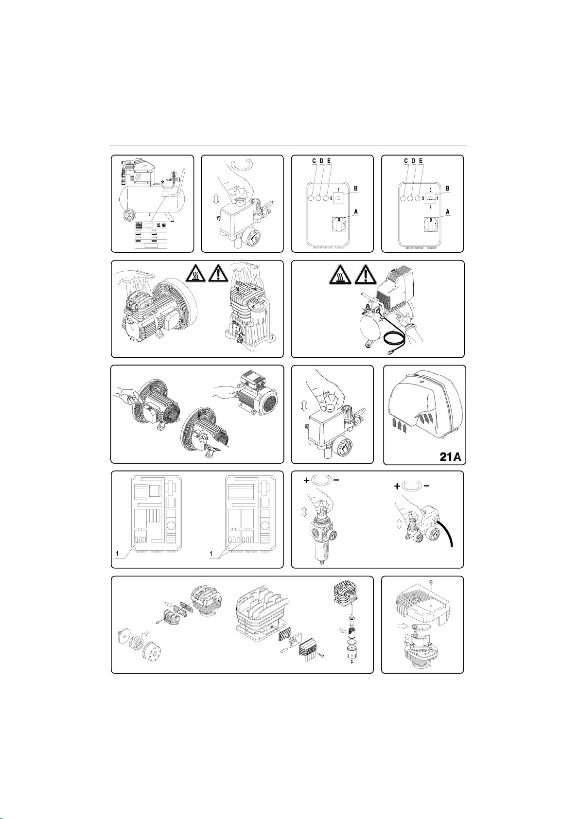
STARTING
Check that the mains power matches that indicated on the electrical
data-plate (fig.14) – the permissible tolerance range is +/-5%. When
first starting compressors operating on 3-phase voltage, check the
rotation direction of the cooling fan by comparing it with the direction of
the arrow on the belt guard or on the protective housing. In the SILENT
compressor, check if the air flows is in the direction illustrated in fig.21A.
Turn or press into position “0” (according to the type of pressure switch
fitted on the appliance) the knob located on the upper section (fig. 15).
Fit the plug in the power socket (fig. 12 - 13) and start the compressor,
turning the pressure switch knob into position “I”. The compressor is
fully automatic, and is controlled by the pressure switch which stops it
when tank pressure reaches maximum value and restarts it when it falls
to minimum value. The pressure difference between maximum and
minimum values is usually about 2 bar (29 psi).
E.g.: the compressor stops when it reaches 8 bar (116 psi – maximum
operating pressure) and restarts automatically when the pressure inside
the tank drops to 6 bar (87 psi).
After connecting the compressor to the power line, load it to maximum
pressure and check exactly how the machine is operating.
solenoid-valve indicator-light “D” and the motor (C) indicator-light (C) go
on in that order, this means the machine is operating perfectly (fig. 18).
TANDEM COMPRESSORS WITH TIMED
CONTROL UNIT (fig. 17)
Fit the plug in the power socket (fig. 13) and turn the pressure switch to
position “I” (ON). Turn the master power switch “A” on the control unit to
position I – power On is signalled by white indicator-light “E” going on.
Turn switch “B” to start the compressor.
Pos. 1 pumping element n. 1 only is operating
Pos. 2 pumping element n. 2 only is operating
Pos. 3 both pumping elements are operating simultaneously, at staggered
starting times.
The compressor is fully automatic, and is controlled by the pressure
switch which stops it when tank pressure reaches maximum value and
restarts it when it falls to minimum value.
NOTE: The head/cylinder/delivery tube unit can reach
high temperatures. Take care when working near these parts, and do
not touch them to avoid possible burns (fig. 18 - 19).
IMPORTANT
The electro-compressors must be connected to a power socket protected
by a suitable differential switch (thermal-breaker). The motor of GM-TR
compressors is equipped with an automatic thermal breaker located
inside the winding – this stops the compressor when motor temperature
reaches excessively high values.
If the breaker is tripped, the compressors restarts automatically after
10 to 15 minutes. The motors of compressor models VX are supplied
with a manually resetting automatic amperometric thermal-breaker,
located outside the terminal board cover.
When the breaker is tripped, wait for a few minutes and then reset the
breaker manually (fig. 20).
The motors of the AB series compressors are supplied with a manually
resetting amperometric thermal-breaker, located on the terminal board
cover. When the breaker is tripped, wait for a few minutes and then
reset the breaker manually (fig. 20).
The safety davice is automatic in three-phase and silent compressors.
When the thermal-breaker is tripped, the pressure switch is released to
“0” (OFF) position.
Wait for a few minutes and return the pressure switch to “I” (ON) position
(with the exception of models: AB 100/245-335 Three-phase -AB 150/
245-335 Three-phase - AB 200/245-335 Three-phase). For
compressors supplied with a control unit, the thermal-breaker is installed
inside the control unit. When the thermal-breaker is tripped, observe
the following procedure (fig. 22):
• Turn the switches on the control unit cover to position “0”, open the
cover and press push-button 1 of the thermal-breaker. Close the
cover of the control unit and restart the compressor, observing the
operations described in the paragraph “Starting compressors with
control unit”.
The same instructions apply to compressors powered at 60 Hz.
ADJUSTING OPERATING PRESSURE (fig. 23)
Y
ou do not have to use the maximum operating pressure at all times. On
the contrary, the pneumatic tool being used often requires less pressure.
On compressors supplied with a pressure reducer, operating pressure
must be correctly adjusted.
COMPRESSORS WITH
Y
D STARTING
Release the pressure reducer knob by pulling it up, adjust pressure to
CONTROL UNIT (fig. 16)
the required value by turning the knob clockwise to increase pressure
Fit the plug in the power socket (fig. 13) and turn the pressure switch to
and anti-clockwise to reduce it. When you have obtained optimum
position “I” (ON) (fig. 17). Turn the master power switch “A” on the control
pressure, lock the knob by pressing it downward (fig. 23). For pressure
unit to position I – power On is signalled by white indicator-light “E”
reducers equipped without a pressure gauge, the set pressure can be
going on. Turn switch “B” to position 1 to start the compressor. If the
seen on the graduated scale located on the reducer body.

17
GB
On pressure reducers equipped with a pressure gauge, pressure can
be seen on the gauge itself.
WARNING: Some pressure regulators do not have "push to lock",
therefore simply turn the knob to adjust the pressure.
MAINTENANCE
Before attempting any maintenance jobs on the compressor, make sure
of the following:
– Master power switch in position “0”.
– Pressure switch and the control unit switches all off, in position “0”.
– No pressure in the air tank.
Every 50 hours of duty: we advise you to dismantle the suction filter and
clean the filtering element by blowing compressed air on it (fig. 24).
You are recommended to replace the filter element at least once if the
compressor operates in a clean environment, but more frequently if in a
dusty environment.
In the “red-head” models (fig. 25) (TR200 – TR255), the suction filter is
located internally under the conveying cover (read-head). Unscrew the
three cover securing screws, remove the cover from the guard joint,
remove the filter from its seat, and begin cleaning, blowing compressed
air in opposite to normal flow direction.
In the Silent model, the filtering element can be replaced by taking off
the soundproofing cabinet and proceeding in the same way as for the
AB models (fig.29A).
The compressor generates condensate water which accumulates in the
tank.
The condensate in the tank must be drained at least once a week, by
opening the drain tap (fig. 26) under the tank.
Take care if there is compressed air inside the cylinder, and water could
flow out with considerable force. Recommended pressure: 1 – 2 bar
max.
Condensate of compressors that are oil lubricated must not be drained
into the sewer or dispersed in the environment as it contains oil.
OIL CHANGES – TOPPING UP WITH OIL
The compressor is filled with synthetic oil “FIAC Oil Synthesis”.
We recommend a full change of oil in the pumping element within the
first 100 hours of duty.
The soundproofing cabinet is to be taken off first in the Silent model
(fig.29A).
Unscrew the oil drain plug on the housing cover, allow all the oil to flow
out, and re-screw the plug (fig. 27 - 28).
Pour oil into the upper hole of the housing cover (fig. 29 - 30) until it
reaches the level indicated on the stick (fig. 9) or indicator (fig. 11)
Pour oil into the upper hole of the head (fig. 30) in belt assisted units
designed for topping up in that area.
For the GM203 series, take the cap off and pour in 85 grams of oil
directly from the bottle (see fig. 30a).
Once a week: check oil level of the pumping element (fig. 11) and see if
it needs topping up.
For operation at ambient temperature in the range -5°C to +40°C, use
synthetic oil. The advantage of this oil is that is does not lose its
characteristics either in winter or summer.
Do not drain used oil into the sewer or dispose of it in the environment.
OBSERVE THIS TABLE FOR OIL CHANGES
TYPE OF OIL HOURS OF DUTY
FIAC Oil Synthesis...................................500
Synthetic oil:
AGIP Sint 2000 Evolution - BP Visco 5000 - ESSO Ultron -
MOBIL Mobil 1 - NILS Dimension S - NUOVA STILMOIL
Arrow5W50............................................400
Other types of oil: mineral multigrade
SAE 15 W40...........................................100
WHAT TO DO IF SMALL MALFUNCTIONS OCCUR
Loss of air in valve under pressure switch
This trouble depends on poor tightness of the check valve – take
the following action (fig. 31):
– Discharge all pressure from the tank
- Unscrew the hexagon-head of the valve (A)
- Carefully clean both the rubber disk (B) and its seat.
- Refit all parts accurately.
Air losses
These can be caused by poor tightness of a union – check all unions,
wetting them with soapy water.
Compressor turns but does not load
Coaxial compressors: (fig. 32)
- this may be due to failure of the valves (C1 – C2) or of a seal (B1 –
B2): replace the damaged part.
Pulley drive compressors: (fig. 33)
- this may be due to failure of the valves F1 and F2 or of a seal (D1 –
D2): replace the damaged part.
GM 203 compressors:
This may be due to the breakage of the valves (C1 - C2) or of the
gasket (B1). Replace the damaged part (fig. 16A).
- Check if there is too much condensate water inside the tank.
Compressor no starting
If the compressor has trouble starting, check the following :
- Does mains power match that of the data-plate? (fig. 14)
- Are power cable extensions of adequate diameter or length?
- Is the work environment too cold? (under 0°C)
- For series VX/AB: was the thermal-breaker tripped? (fig. 20); in the
silent series (fig. 21)
- Is there oil in the housing to ensure lubrication? (fig. 11)
- Is power supplied to the electrical line? (sockets well connected,
thermal- breaker, fuses in good condition).
Compressor not stopping
- If the compressor does not stop when maximum pressure is reached,
the tank safety valve comes into operation. To repair the valve, contact
your nearest service centre.
IMPORTANT
- Do not on any account unscrew any connection while the tank is
pressurised – always check if the tank is pressure free.
- Do not drill holes, weld or purposely deform the compressed air tank.
- Do not do any jobs on the compressor unless you have disconnected
the power plug.
- Temperature in operating ambient: 0°C +35°C.
- Do not aim jets of water or inflammable liquids on the compressor.
- Do not place inflammable objects near the compressor.
- During down-times, turn the pressure switch to position “0” (OFF).
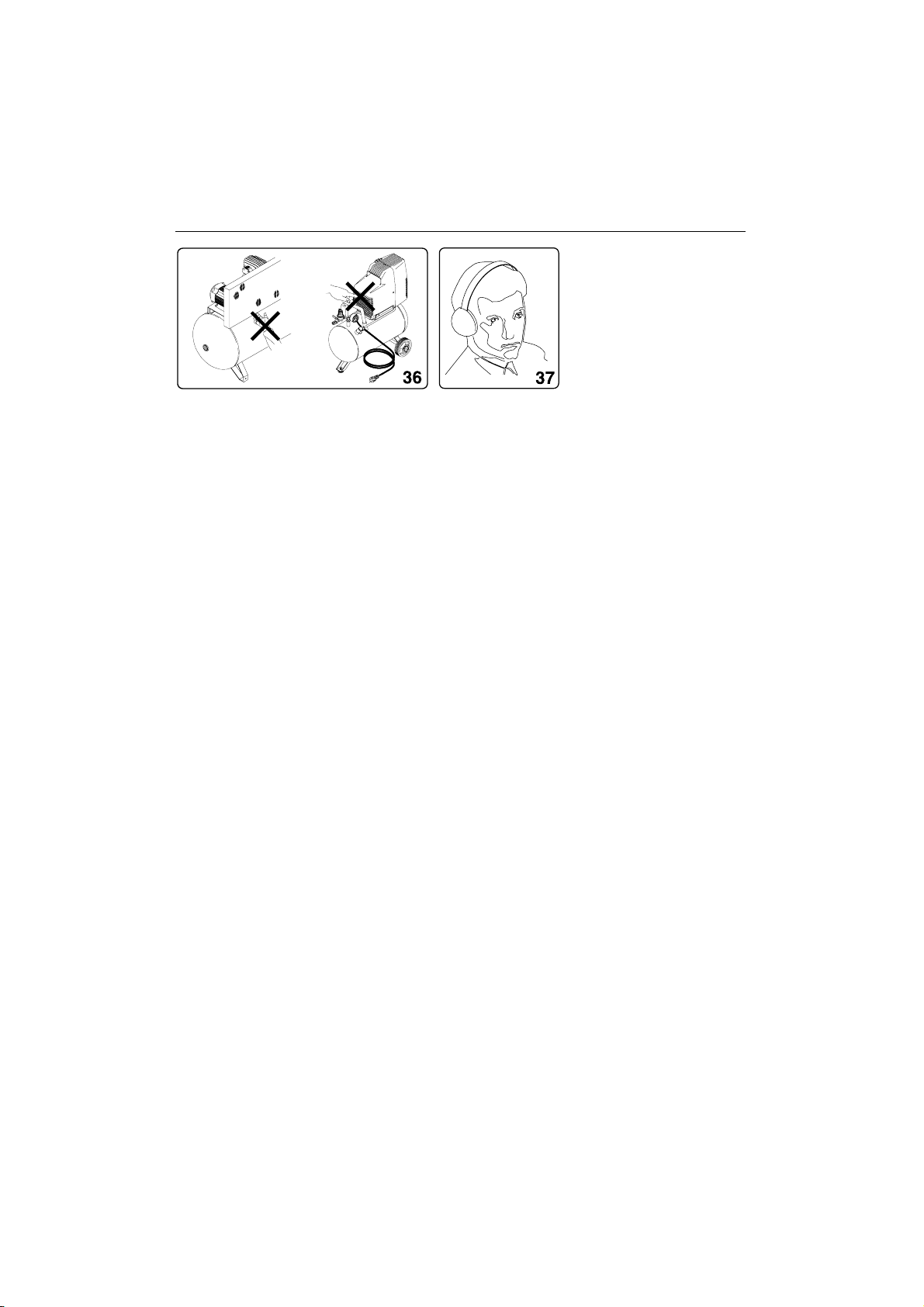
- Never aim the air jet at people or animals (fig. 34)
- Do not transport the compressor while the tank is pressurised.
- Be careful with regard to some parts of the compressor such as the
head and delivery tubes, as they can reach high temperatures. Do
not touch these parts to avoid burns.(fig. 18 - 19)
- Transport the compressor, lifting or pulling it with the appropriate grips
or handles (fig. 4 - 6)
- Keep children and animals well away from the machine operating
area.
- If using the compressor for painting:
a) Do not work in closed environments or near to naked flames
b) Make sure there is adequate exchange of air at the place of work
c) Protect your nose and mouth with an appropriate mask. (fig. 35)
- If the electrical cable or plug are damaged, do not use the compressor
and contact an authorised service centre to replace the faulty element
with an original spare part.

GB 18
- If the compressor is located on a shelf or on a top above floor height,
it must be secured to prevent it falling while in operation.
- Do not put objects or your hands inside the protective grilles to avoid
injury to yourself or damaging the compressor. (fig. 36)
- Do not use the compressor as a blunt object toward things or animals,
to avoid serious damage.
- When you have finished using the compressor, always remove the
plug from the power socket.
ELECTRO-COMPRESSOR MODELS GM – TR
Maximum operating pressure 8.5 bar
Minimum operating pressure 8 bar
ELECTRO-COMPRESSOR MODELS VX
Maximum operating pressure 10.5 bar
Minimum operating pressure 10 bar
ELECTRO-COMPRESSOR MODELS AB
Maximum operating pressure 10.5 bar
Minimum operating pressure 10 bar
N.B. Two-stage compressors can be supplied on request for use up to
14 bar. In this case:
Maximum operating pressure 14.75 bar
Minimum operating pressure 14 bar
NOTE: The Silent model consists of the AB model completed with a
soundproofing cabinet. The technical data and the instructions of this
manual for the AB models also apply to the derived Silent models.
For the European market, the compressor tanks are manufactured to
meet Directive CE87/404
For the European market, the compressors are manufactured to meet
Directive CE98/37.
Acoustic pressure measured free-field at a distance of 1m: ±3dB(A) at
maximum operating pressure. (tab. 3)
The level of acoustic pressure can increase from 1 to 10 dB(A)
according to the place in which the compressor is installed.
HINTS FOR EFFICIENT OPERATION
- For efficient operation of the machine at full continuing load and at
maximum operating pressure, make sure the temperature of the work
environment indoors does not exceed +25°C.
- We advise you to use the compressor at 70% maximum duty per
hour at full load as this ensures efficient operation of the product
long-term.
STORING THE PACKED AND UNPACKED COMPRESSOR
For the whole time that the compressor is not used before unpacking it,
store it in a dry place at a temperature between +5°C and + 45°C and
sheltered away from weather.
For the whole time that the compressor is not used after unpacking it,
while waiting to start it up or due to production stoppages, place sheets
over it to protect it from dust, which may settle on the components. The
oil is to be replaced and the operational efficiency of the compressor is
to be checked if it is not used for long periods.
PNEUMATIC CONNECTIONS
Make sure you always use pneumatic tubes for compressed air with
maximum pressure characteristics that are adequate for the compressor.
Do not attempt to repair tubes if faulty.
WE RESERVE THE RIGHT TO MAKE ANY MODIFICATIONS
WITHOUT PRIOR NOTICE WHENEVER NECESSARY.
GM VX
HP/kW RPM dB(A) HP/kW RPM dB(A)
0.65/0.5 1450 73 1.5/1.1 1450 75
0.65/0.5 2800 75 2/1.5 1700-1450 75
0.75/0.65 1700-1450 73 2.5/1.8 14050 75.5
1.5/1.1 3400-2850 75 3/2.2 2850 80
2/1.5 2850 79 / / /
2.5/1.8 2850 82
TR
HP/kW RPM dB(A)
1.5/1.1 1700-2800 7 6
2/1.5 2800 80
AB
Mod. HP/kW dB(A)
CCS 2 – 1.5 77
AB 245 2 – 1.5 78
AB 335 3 – 2.25 80
AB 410 3 – 2.25 80
AB 510 4 – 3 85
AB 480 4 – 3 81
AB 530 4 – 3 82
AB 550 5.5 – 4.1 83
AB 671 5.5 – 4.1 84
AB 851 7.5 – 5.5 83
AB 1000 10 – 7.5 88

19 F
INFORMATIONS IMPORTANTES
Lire attentivement toutes les instructions de fonctionnement, les
consignes de sécurité et les mises en garde contenues dans ce manuel
avant de faire fonctionner le compresseur ou de procéder à son entretien.
La majorité des accident résultant de l’utilisation ou de l’entretien du
compresseur sont dus au non respect des consignes et règles de sécurité
élémentaires. En indentifiant à temps les situations potentiellement
dangereuses et en observant les consignes de sécurité appropriées,
on évite bien souvent des accidents.
Les consignes élémentaires de sécurité sont décrites dans la section
“SÉCURITÉ” de ce manuel ainsi que dans les sections renfermant les
instructions d’utilisations et d’entretien.
Ne jamais utiliser le compresseuer d’une manière autre que celle
spécifiquement recommandées, à moins de s’être prélablement assuré
que l’utilisation envisagée ne sera dangereuse ni pour soi ni pour les
autres.
SIGNIFICATION DU VOCABULAIRE DE SIGNALISATION
AVERTISSEMENT: indique une situation potentiellement dangereuse
qui, s’il n’est pas tenu compte de son caractère, risque de provoquer de
graves blessures.
PRÉCAUTION: indique une situation dangereuse qui, s’il n’est pas tenu
compte de son caractère, risque de provoquer des blessures légères
ou d’endommager la machine.
REMARQUE: souligne une information essentielle
SÉCURITÉ
CONSIGNES DE SÉCURITÉ IMPORTANTES
POUR L’UTILISATION DU COMPRESSEUR
AVERTISSEMENT:
UNE UTILISATION DU COMPRESSEUR DE MANIÈRE
INCORRECTE OU QUI NE RESPECTE PAS LES CONSIGNES DE
SÉCURITÉ PEUT ENTRAÎNER LA MORT OU DE GRAVES
BLESSURES. POUR ÉVITER TOUT DANGER, OBSERVER CES
CONSIGNES ÉLÉMENTAIRES DE SÉCURITÉ.
BIEN LIRE TOUTES LES INSTRUCTIONS
1. NE JAMAIS TOUCHER AUX PIÈCES MOBILES
Ne jamais approcher les mains, les doigts ou aucune autre partie
du corps des pièces mobiles du compresseur.
2. NE JAMAIS FAIRE FONCTIONNER LE COMPRESSEUR SI TOUS
LES GARDES PROTECTEURS NE SONT PAS EN PLACE
Ne jamais faire fonctionner le compresseur si tous les gardes
protecteurs ou dispositifs de sécurité ne sont pas en place et en
bon état. Si une opération d’entretien ou de réparation nécessite le
démontage d’un garde protecteur ou d’un dispositif de sécurité, bien
le remonter avant de remettre le compresseur en marche.
3. TOUJOURS SE PROTÉGER LES YEUX
Toujours porter des lunettes ou un masque de protection oculaier.
Ne jamais diriger le jet d’air comprimé sur une personne ou une
partie du corps.
4. SE PROTÉGER CONTRE LES DÉCHARGES ÉLECTRIQUES
Empêcher tout contact du corps avec les surfaces mises à la terre,
par exemple les tuyaux, radiateurs, plaques de cuisson et enceintes
de réfrigération. Ne jamais faire fonctionner le compresseur dans
un endroit humide ou sur une surface mouillée.
5. DÉBRANCHER LE COMPRESSEUR
Toujours débrancher le compresseur de sa source d’alimentation et
évacuer l’air comprimé de son réservoir avant toute opération de
réparation, d’inspection, d’entretien, de nettoyage, de remplacement
ou de vérification des pièces.
6. ÉVITER TOUTE MISE EN MARCHE ACCIDENTELLE
Ne pas transporter le compresseur alors qu’il est encore raccordé à
sa source d’alimentation ou que le réservoir d’air comprimé est plein.
Bien s’assurer que le sélecteur de l’interrupteur barométrique se
trouve sur la position “OFF” (arrêt) avant de raccorder le compresseur
à son alimentation.
7. ENTREPOSER CORRECTEMENT LE COMPRESSEUR
Veiller à ce qu’il soit hors de portée des enfants. Fermer à clé le
local d’enterposage.
8. MAINTENIR L’AIRE DE TRAVAIL PROPRE
Une aire de travail encombrée augemente les risque d’accident. La
débarrasser des outils inutiles, débris, meubles, etc.
9. SE SOUCIER DE L’ENVIRONMENT DE TRAVAIL
Ne pas exposer le compresseur à la pluie. Ne pas l’utiliser dans un
endroit humide ou sur une surface mouillée. Veiller à ce que l’aire
de travail soit bien éclairée et bien aérée. Ne pas utiliser le
compresseur en présence de liquides ou de gaz inflammables. Les
compresseur projette des étincelles pendant qu’il fonctionne. Ne
jamais l’utiliser à proximité de laque, de peinture, de benzine, de
diluant, d’essence, de gaz, de produits adhésifs ou de tout autre
produit combustible ou explosif.
10. ÉLOIGNER LES ENFANTS
Ne pas laisser les visiteurs toucher aur cordon de rallonge du
compresseur. Tous les visiteurs devront se tenir suffisamment
éloignés de l’aire de travail.
11. SE VÊTIR CORRECTEMENT
Ne porter ni vêtements lâches ni bijoux. Ils pourraient se prendre
dans les pièces mobiles. Porter un coiffe recouvrant les cheveux
longs.
12. FAIRE ATTENTION AU CORDON
Ne jamais tirer brusquement sur le cordon pour le débrancher. Tenir
le cordon loin des sources de chaleur, de graisse et des surfaces
tranchantes.
13. ENTRETENIR LE COMPRESSEUR AVEC SOIN
Suivre les instructions de lubrification. Inspecter régulièrement les
cordons et, s’il sont endommagés, les faire réparer dans un centre
de service après-vente agrée. Inspecter périodiquement les cordons
de rallonge et les faire réparer s’ils sont endommagés.
14. CORDONS DE RALLONGE POUR UTILISATION À L’EXTÉRIEUR
Si l’outil doit être utilisé dehors, utiliser exclusivement des cordons
de rallonge conçus pour l’extérieur et identifiés comme tels.
15. RESTER SUR SES GARDES
Bien faire attention à ce que l’on fait. Faire preuve de bon sens. Ne
pas utiliser le compresseur lorsque l’on est fatigués. Ne jamais utiliser
le compresseur si l’on est sous l’effet d’alcool, de drogues ou de
médicaments causant de la somnolence.
16. CONTRÔLER LES PIÉCES ENDOMMAGÉES ET LES FUITES
D’AIR
Avant de continuer à utiliser le compresseur, inspecter attentivement
les protections ou autres pièces endommagées pour s’assurer que
le compresseur pourra fonctionner correctement et effectuer le travail
pour lequel il est conçu. Vérifiez l’alignement et le couplage des
pièces mobiles, la présence de pièces brisées, le montage, les fuites
d’air et tout autre élément susceptible d’altérer le bon fonctionnement.
17. UTILISER LE COMPRESSEUR EXCLUSIVEMENT POUR LES
APPLICATIONS SPÉCIFIÉES DANS LE MANUELD’UTILISATION
Ne jamais utiliser le compresseur pour des utilisations autres que
celles spécifiées dans le manuel.
18. MANIPULER LE COMPRESSEUR CORRECTEMENT
Faire fonctionner le compresseur conformément aux instructions
de ce manuel. Ne jamais laisser les enfants, les personnes non

F20
familiarisées avec son fonctionnement ou toute personne non
autorisée utiliser le compresseur.
19. VÉRIFIER QUE CHAQUE VIS, BOULON ET COUVERCLE EST
SOLIDEMENT VISSÉ
Veiller à ce que chaque vis, boulon et plaque soit solidement vissé.
Vérifier périodiquement le serrage.
20. MAINTENIR L’ÉVENT D’AÉRATION DU MOTEUR PROPRE
L’évent d’aération du moteur doit rester propre en permanence de
façon à ce que l’air puisse circuler librement. Contrôler fréquemment
l’accumulation de poussière.
21. FAIRE FONCTIONNER LE COMPRESSEUR À LA TENSION
NOMINALE
Faire fonctionner le compresseur à la tension spécifiée sur la plaque
signalétique. Si le compresseur est utilisé à une tension supérieure
à la tension nominale, il en résultera une vitesse de rotation du moteur
anormalement élevée risquant d’endommager le compresseur et
de griller le moteur.
22. NE JAMAIS UTILISEER UN COMPRESSEUR DÉFECTUEUX OU
DONT LE FONCTIONNEMENT EST ANORMAL
Si le compresseur semble ne pas fonctionner, s’il émet un bruit bizarre
ou qu’il semble défectueux, l’arrêter immédiatement et le faire réparer
dans un centre de service après-vente agrée.
23. NE PAS NETTOYER LES PIÈCES DE PLASTIQUE AVEC DU
SOLVANT
Les solvants tels qu’essence, diluant, benzine, tétrachlorure de
carbone et alcool risquent d’endommager et de fendre les pièces
de plastique. Ne pas les nettoyer avec ce genre de produit. Pout
nettoyer le pièces de plastique, utiliser un linge doux humecté d’eau
savonneuse puis sécher complètement.
24. UTILISER EXCLUSIVEMENT DES PIÈCES DE RECHANGE
D’ORIGINE
L’utilisation de pièces de rechange autres que celles fabriquées, peut
entraîner l’annulation de la garantie et être la cause d’un mauvais
fonctionnement et des blessures en résultant. Les pièces d’origine
sont disponible auprès de son distributeur.
25. NE PAS MODIFIER LE COMPRESSEUR
Ne pas modifier le compresseur. Toujours consulter un centre de
service après-vente agréé pour toute réparation. Une modification
non autorisée risque non seulement d’affecter les performances du
compresseur, mais également d’être la cause d’accidents et de
blessures pour le personnel de réparation qui ne posséderait pas
les compétences techniques nécessaires.
26. DÉSACTIVER L’INTERRUPTEUR BAROMÈTRIQUE LORSQU’ON
NE SE SERT PAS DU COMPRESSEUR
Quand le compresseur ne fonctionne pas, régler le sélecteur de
l’interrupteur barométrique sur “OFF”, débrancher le compresseur
et ouvrir le robinet de vidange pour vider le réservoir d’air comprimé.
27. NE JAMAIS TOUCHER LES SURFACES CHAUDES
Pour éviter tout risque de brûlures, ne pas toucher les tubes, les
culasses ni les moteurs.
28. NE PAS DIRIGER LE JET D’AIR DIRECTEMENT SUR LE CORPS
Sous peine de blessures, ne pas diriger le jet d’air sur des personnes ou
des animaux.
29. VIDANGER LE RÉSERVOIR
Vidanger le réservoir tous les jours ou toutes les 4 heures d’utilisation.
Ouvrir le bouchon de vidange et incliner le compresseur pour vider
l’eau qui s’est accumulée.
30. NE PAS ARRÊTER LE COMPRESSEUR EN TIRANT SUR LA
FICHE
Utiliser la position “AUTO/OFF” du sélecteur de l’interrupteur
barométrique.
31. POUR LE CIRCUIT PNEUMATIQUE, N’UTILISER QUE DES
PIÈCES RECOMMADÉES SUPPORTANT UNE PRESSION
SUPÉRIEURE OU ÉGALE À 125PSI
l y a risque d’explosion. N’utiliser que des pièces pneumatiques
recommandées supportant une pression supérieur ou égale à 125
psi.
PIÈCES DE RECHANGE
Pour le réparations, utiliser uniquement des pièces de rechange
identiques aux pièces remplacées.
Confier toute réparation à un centre de service après-vent agréé.
AVERTISSEMENTS
INSTRUCTIONS POUR LE BRANCHEMENT A LA TERRE
Ce compresseur doit être relié à la terre lorsqu’il est en cours d’utilisation
afin de protéger l’opérateur des décharges électriques.
Le compresseur monophasé est équipé d’un câble bipolaire plus terre.
Le compresseur triphasé est fourni avec un câble électrique sans fiche.
Le branchement électrique doit être exécuté par un technicien qualifié.
Il est recommandé de ne jamais démonter le compresseur ni effectuer
d’autres connexions au niveau du pressostat.
Les réparations doivent être effectuées uniquement par des centres de
service après-vente autorisés ou par d’autres centres qualifiés.
Ne jamais oublier que le fil de mise à la terre est le fil vert ou jaune/vert.
Ne jamais brancher ce fil vert à une extrémité vive.
Avant de remplacer la fiche du câble d’alimentation, vérifier que le
branchement du fil de terre est effectué.
En cas de doute contacter un électricien qualifié et faire contrôler la
mise à la terre.
RALLONGE
Utiliser uniquement une rallonge avec fiche et branchement à la terre,
ne pas utiliser de rallonges endommagées ou écrasées.
Vérifier que la rallonge soit en bon état.
Contrôler que la section du câble de rallonge soit suffisante pour
supporter le courant absorbé par le produit qui sera branché.
Une rallonge trop fine peut provoquer des chutes de tension et, par
conséquent, une perte de puissance ainsi qu’une surchauffe de l’appareil.
Le câble de rallonge des compresseurs monophasés doit avoir une
section proportionnée à sa longueur, voir tableau (tab.1)
Tab. 1
SECTION VALABLE POUR UNE LONGUEUR
MAXIMUM DE 20 mt monophasé
CV kW 220/230 V 110/120V
mm
2
mm
2
0.75 - 1 0.65 - 0.7 1.5 2.5
1.5 1.1 2.5 4
2 1.5 2.5 4 - 6
2.5 - 3 1.8 - 2.2 4 /
Le câble de rallonge des compresseurs triphasés doit avoir une section
proportionnée à sa longueur : voir tableau (tab. 2).
Tab. 2
SECTION VALABLE POUR UNE LONGUEUR
MAXIMUM DE 20 m. triphasé
CV kW 220/230 V 380/400V
mm
2
mm
2
2 – 3 - 4 1.5 - 2.2 - 3 2.5 1.5
5.5 4 4 2
7.5 5.5 6 2.5
10 7.5 10 4
AVERTISSEMENTS
Eviter tous les risques de décharges électriques.
Ne jamais utiliser le compresseur avec une rallonge ou un câble

21F
électrique endommagé.
Contrôler régulièrement les câbles électriques.
Ne jamais utiliser le compresseur dans l’eau ou à proximité de celle-ci
ainsi qu’à proximité d’un lieu avec risque de décharges électriques.
CONSERVER LES INSTRUCTIONS D’UTILISATION ET
D’ENTRETIEN ET LES METTRE A DISPOSITION DES
PERSONNES QUI UTILISENT CET APPAREIL!
UTILISATION ET ENTRETIEN
REMARQUE:Les informations indiquées dans ce manuel ont pour
objectif d’assister l’opérateur durant l’utilisation et les opérations
d’entretien du compresseur.
Certaines illustrations de ce manuel indiquent certains détails qui peuvent
être différents de ceux de votre compresseur.
INSTALLATION
Après avoir déballé le compresseur (fig. 1), vérifier qu’il est en bon état
en contrôlant qu’il n’ait pas subi de dommages durant la transport puis
effectuer les opérations suivantes:
Monter les roues et le caoutchouc sur les réservoirs (lorsqu’ils ne sont
pas déjà montés) en suivant les instructions de la fig. 2. En cas de roues
gonflables, gonfler à une pression maximale de 1,6 bar (24 psi).
Positionner le compresseur sur une surface plane ou avec une inclinaison
maximale de 10°(fig. 3), dans un lieu bien ventilé, à l’abri des agents
atmosphériques et non dans des endroits présentant des risques
d’explosion. En cas de plan incliné et lisse, vérifier que le compresseur
ne se déplace pas en cours de fonctionnement, dans le cas contraire,
bloquer les roues avec deux cales.
Si le plan est un support ou un échafaudage, fixer le compresseur de
façon appropriée afin d’éviter les chutes.
Pour obtenir une bonne ventilation et un refroidissement efficace, il est
important que la protection courroie du compresseur soit à au moins
100 cm de distance de toute cloison (fig. 4).
Les compresseurs montés sur réservoir à pieds fixes ne doivent pas
être fixés au sol de façon rigide, il est conseillé de monter 4 supports
antivibrants.
INSTRUCTIONS D’UTILISATION
– Faire attention que le compresseur soit transporté correctement, ne
pas le retourner ou le soulever avec des crochets ou câbles (fig. 5 –
6).
– Remplacer le bouchon en plastique situé sur le couvercle carter (fig.
7 – 8) avec la tige de niveau d’huile (fig. 9) ou avec le bouchon de
purge approprié (fig. 10) fourni avec le manuel d’instructions, contrôler
le niveau d’huile en prenant les encoches situées sur la tige (fig. 9)
ou le témoin de niveau d’huile (fig. 11) comme référence.
BRANCHEMENT ELECTRIQUE
Les compresseurs monophasés sont fournis avec un câble bipolaire
et une fiche bipolaire + terre.
Il est important que le compresseur soit branché à une prise de courant
doté de mise à la terre (fig. 12).
Les compresseurs triphasés (L1 - L2 - L3 - PE) doivent être installés par
un technicien qualifié.
Les compresseurs triphasés sont fournis sans fiche.
Relier au câble d’alimentation une fiche électrique avec passe-câble à
CV kW Aliment. volt/ph Type de fiche
2 – 3 - 4 1.5-2.2-3 220/380/3
230/400/3 16A 3 pôles + terre
5.5 - 7.5 - 10 4-5.5-7.5 220/380/3
230/400/3 32A 3 pôles + terre
REMARQUE: Les compresseurs montés sur réservoir de 500 l. avec
une puissance de CV7.5/55 kW et CV10/7.5 sont disponibles avec
boîtier de démarrage étoile/triangle tandis que les modèles TANDEM
(n°2 pompes sur le même réservoir) sont disponibles avec boîtier
temporisé pour le départ différencié des deux pompes.
Pour l’installation, procéder comme suit:
– Fixer le boîtier au mur ou sur un support fixe, l’équiper d’un câble
d’alimentation avec fiche électrique et d’une section proportionnée
à la longueur.
– Tout dommage provoqué par de mauvais branchements à la ligne
annule automatiquement la garantie sur les pièces électriques. Afin
d’éviter tout branchement incorrect, contacter un technicien qualifié.
ATTENTION: Ne jamais utiliser la prise de terre à la place du neutre.
Le branchement à la terre doit être effectué selon les normes de
prévention des accidents du travail (EN 60204).
La fiche du câble d’alimentation ne doit pas être utilisée comme
interrupteur mais doit être introduite dans une prise de courant
commandée par un interrupteur différentiel approprié
(magnétothermique).
DEMARRAGE
Contrôler que la tension de réseau correspond à celle indiquée sur la
plaquette signalétique des caractéristiques électriques (fig. 14), la plage
de tolérance admise est de ±5%.
Au moment de la première mise en service, pour les compresseurs qui
fonctionnent avec une tension triphasée, vérifier le sens exact de rotation
du ventilateur de refroidissement au moyen de la flèche située sur la
protection courroie ou sur le carénage. Dans le compresseur SILENT,
contrôler que le débit d’air est bien dans la direction indiquée dans la
figure 21A.
Tourner ou appuyer, en fonction du type de pressostat présent sur
l’appareil, le pommeau situé sur la partie supérieure en position “0” (fig.
15).
Introduire la fiche dans la prise de courant (fig. 12 - 13) et démarrer le
compresseur en positionnant le pommeau du pressostat sur (I).
Le fonctionnement du compresseur est entièrement automatique,
commandé par le pressostat qui l’arrête lorsque la pression dans le
réservoir atteint la valeur maximum et le fait repartir lorsqu’elle descend
en dessous de la valeur minimum.
Généralement, la différence de pression entre la valeur maximum et la
valeur minimum est d’environ 2 bars (29 psi).
Ex.: le compresseur s’arrête lorsqu’il atteint 8 bars (116 psi) (pression
maximum de fonctionnement) et redémarre automatiquement lorsque
la pression à l’intérieur du réservoir descend à 6 bars (87 psi).
Après avoir branché le compresseur à la ligne électrique, effectuer une
charge à la pression maximum et vérifier que le fonctionnement de la
machine soit correct.
COMPRESSEURS AVEC BOITIER
vis et collier de blocage (fig. 13) après avoir consulté le tableau ci- DE DEMARRAGE
dessous.
Y
D(fig. 16)
Introduire la fiche dans la prise de courant (fig.13), positionner le
pressostat sur “I” (ON) (fig. 17).
Tourner l’interrupteur principal d’alimentation “A” du boîtier sur “I”, la
présence du courant est signalé par l’allumage du témoin blanc “E”.
This manual suits for next models
6
Table of contents
Languages:
Other Aerfast Air Compressor manuals


Popular Air Compressor manuals by other brands

Hitachi
Hitachi EC 129 Safety and instruction manual

Husky
Husky C801H Use and care guide

PowerPro Technology
PowerPro Technology 22010 Operator's manual

Kellogg-American
Kellogg-American V120103-452 instruction manual

Craftsman
Craftsman 919.165511 owner's manual

Rogers
Rogers KI Series Installation, operation and maintenance manual


DeWalt
DeWalt Contractor's Electric Wheeled Portable Air Compressor... instruction manual

Danfoss
Danfoss PSH019 Application guidelines

Grupo Urrea
Grupo Urrea Surtek COMP550A user manual

Craftsman
Craftsman 919.150340 owner's manual

Ingersoll-Rand
Ingersoll-Rand SS358B owner's manual

XTline
XTline XT2024 Original instruction manual