AERO-LIFT FORCE-LIFT User manual
1/51 FORCE-LIFT
karto
Machine type:
FORCE-LIFT®Vacuum Lifter
Version:
02/2021
Built in:
2022
Application:
For the horizontal transport of airtight an porous
materials. Load capacity up to 75kg depending
on the configuration
Carefully read and observe the instruction manual!
Keep the manual readily available for future reference!
INSTRUCTION MANUAL
LEGAL INFORMATION
2/51 FORCE-LIFT®
LEGAL INFORMATION
All rights, especially the right to reproduction, distribution and translation, are reserved. No part of
this document may be reproduced in any form (print, photocopy, microfilm or another process)
nor stored, processed or distributed using electronic systems without the written consent of
AERO-LIFT Vakuumtechnik GmbH. Noncompliance will result in seeking damages to cover
losses.
The vacuum lifter complies with CE guidelines in accordance with the applicable
regulations and directives. The applied standards and guidelines are listed in the
declaration of conformity.
Copyright © AERO-LIFT Vakuumtechnik GmbH
AERO-LIFT Vakuumtechnik GmbH
Turmstraße 1
D-72351 Geislingen
Ph: +49 (0) 7428 94 514-0
Fax: +49 (0) 7428 94 514-38
www.aero-lift.de
LIST OF CONTENS
FORCE-LIFT®3/51
INHALTSVERZEICHNIS
1Safety............................................................................................................................................................... 3
Target group ....................................................................................................................................................................3
Abbreviations and definitions............................................................................................................................................4
Type label and nomenclature...........................................................................................................................................4
Further applicable documents..........................................................................................................................................4
Explanation of safety instructions.....................................................................................................................................5
Remaining risks in case of use.........................................................................................................................................7
Operator obligations and liability ......................................................................................................................................9
General safety instructions.............................................................................................................................................10
Intended use..................................................................................................................................................................10
Foreseeable misuse.......................................................................................................................................................10
2Structure and function .................................................................................................................................. 11
Technical specifications .................................................................................................................................................11
Functional Description....................................................................................................................................................12
Operator controls ...........................................................................................................................................................13
Safety devices................................................................................................................................................................14
Components...................................................................................................................................................................15
Suction feet (options).....................................................................................................................................................16
3Installation..................................................................................................................................................... 19
Installing the vacuum lifter..............................................................................................................................................19
Electrical connection......................................................................................................................................................20
4Handling and operation................................................................................................................................. 21
Transporting the product with the vacuum tube lifter ......................................................................................................21
Fastening/changing the suction foot...............................................................................................................................23
5Options, spare and wear parts ...................................................................................................................... 25
Replacement seal ..........................................................................................................................................................25
Further spare parts.........................................................................................................................................................26
AERO-LIFT Service .......................................................................................................................................................26
6Maintenance, inspection and repairs ............................................................................................................ 27
Inspection intervals ........................................................................................................................................................28
Maintenance and repairs................................................................................................................................................29
7Transport, setup and storage ........................................................................................................................ 32
8Disassembly and disposal .............................................................................................................................. 33
9EU Declaration of Conformity........................................................................................................................ 34
10 Annex............................................................................................................................................................. 35
Vacuum pump operating instructions .................................................................Fehler! Textmarke nicht definiert.
1Safety
Target group
SAFETY
4/51 FORCE-LIFT®
These operating instructions have been written for persons, who as a result of their professional
training, work experience and their current work activity have adequate technical knowledge to
safely and competently use the vacuum lifting unit and who are able to read and understand the
instructions.
Abbreviations and definitions
Abbreviation
Definitions
Explanation
UVV
Accident prevention regulations
Maintenance service for accident
prevention
VUSS
Vacuum Unit Sensing System
Flow valves integrated in the suction
feet, which turn on and off
automatically
AL
AERO-LIFT
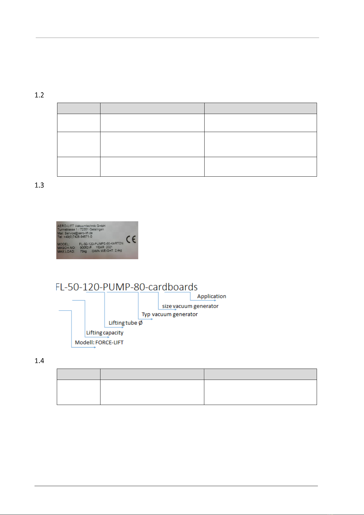
Type label and nomenclature
The machine number, year of manufacture and model designation are are given on the type label
for identification. We ask you to provide this information in a service case.
The type label is attached to the rear of the control head. It is structured as follows:
The specified model name can be deciphered as follows:
Further applicable documents
Appendix No.
Document
Manufacturer
1
Operating instructions, spare parts
list and instructions for sound-
proofing box of the vacuum pump
AERO-LIFT Vakuumtechnik GmbH

LIST OF CONTENS
FORCE-LIFT®5/51
Explanation of safety instructions
Safety instructions are always provided with a signal word and a warning. All persons who work
with the machine must observe and adhere to the safety instructions. The safety instructions are
arranged as follows:
(1) SIGNAL WORD
(5)
(2) Signal word classifies the danger
(3) Note text: type and source of danger + possible consequences
✓(4) Measures to be taken or prohibitions to be imposed
(5) Symbol: supporting graphic representation of the hazard
Categorization Warnings:
DANGER!
Indicates an immediate or impending danger. If appropriate measures are not taken, it
will lead to serious injury or death.
WARNING!
Warns of a potentially dangerous situation. If appropriate measures are not taken, it
may lead to serious injury or death.
CAUTION!
Warns of a potentially dangerous situation. If appropriate measures are not taken, it
may lead to minor or moderate injuries.
NOTE
Indicates possible damage to property and provides specific information
Explanation of symbols
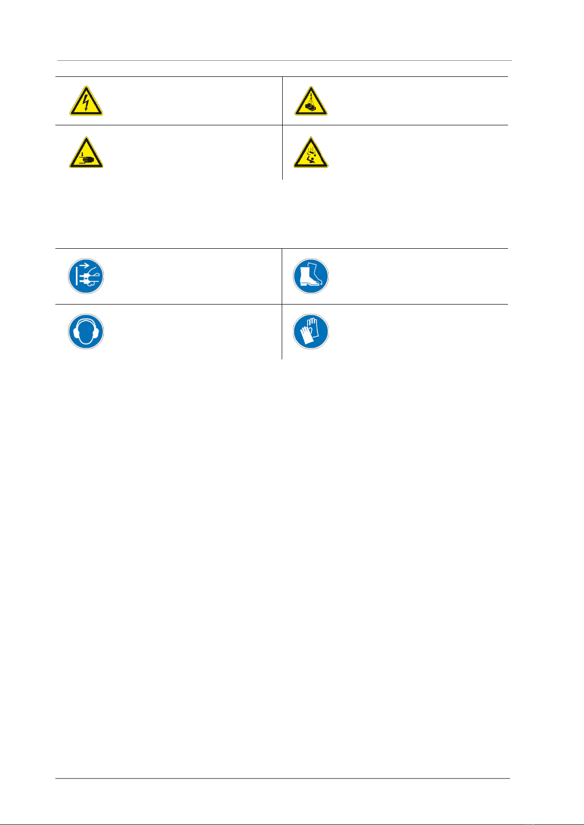
Warning signs:
Warns or indicates a hazardous
area. Different symbols in the
warning triangle explain a danger in
more detail
Warns of tipping over and serious
injury due to crushing
SAFETY
6/51 FORCE-LIFT®
Warns of dangers due to electrical
voltage
Warns of a suspended load
Warns of serious injuries due to
crushing of limbs
Warns of falling objects
Bid signs:
Instructs personnel to unplug the
power cord
Instructs personnel to wear
protective shoes
Instructs personnel to wear
protective clothing
Instructs personnel to wear
protective gloves
LIST OF CONTENS
FORCE-LIFT®7/51
Remaining risks in case of use
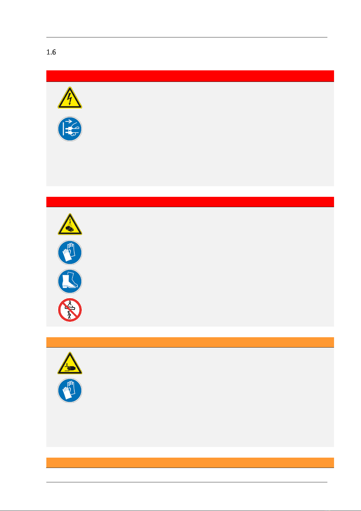
DANGER!
Electrical Voltage!
Contact with live parts is life-threatening! Live parts, damaged electrical lines and
electric shock as a result of faulty or defective parts, or using water to clean may lead to
lethal injuries, burns and property damage.
✓Switch off the power supply prior to carrying out any work on the electrical
system or cleaning.
✓Pull the vacuum power supply plug (disconnect from power supply)!
✓Cleaning may only be carried out by trained personnel.
✓Maintenance of the electrical system may only be carried out by a qualified
electrician.
✓Regular visual inspection of energy chains and electrical lines for any damage.
DANGER!
Suspended loads!
Risk of crushing, shearing and other injuries due to falling or moving parts during
transport of the machine or machine parts and during operation.
Risk when moving loads!
✓Do NOT stand under suspended loads and do not climb on suspended loads!
✓Use suitable lifting gear and load handling attachments that are approved for
transport and the weight!
✓Wear personal protective equipment.
✓Move goods carefully and pick up load at its center of gravity.
✓Persons may NOT stay in the transport area.
WARNING!
Moving parts!
Crushing of fingers / hands when moving or adjusting the position of the suction plates,
during mounting or operation may lead to injuries.
✓Do NOT touch or reach between individual suction plates (double-rectangular
suction foot), quick-changing coupling and suction foot or between other
components!
✓Carefully install the vacuum lifter.
✓Do not remove the protective covers.
✓When moving, keep the one hand on the control head and the other hand on
the product being transported.
✓Always wear personal protective equipment when installing and making
adjustments!
WARNING!

SAFETY
8/51 FORCE-LIFT®
Falling loads!
Incorrect pick-up and/or premature release of loads before they are fully resting can
cause severe injuries due to possible crushing, shearing or impact. Danger due to loads
falling!
✓When operating the vacuum lifter, exercise caution!
✓Pick up load only in center.
✓Only release load when it is fully resting.
✓After changing the suction plates/bases, check whether the connection has
been inserted correctly.
✓Persons may NOT stay in the transport area.
✓Always wear personal protective equipment when working on or with the
machine!
WARNING!
Manual swivelling / turning of suction foot
Risk of injury due to crushing, shearing or impact involving suction foot and/or product
being transported when manually turning and swivelling of the suction foot.
✓Exercise caution when swivelling and turning the suction foot.
✓When swivelling, keep the one hand on the control head and the other hand on
the product being transported.
✓Always wear personal protective equipment when working on or with the
machine!
WARNING!
Danger of being drawn in
Risk of injury from being drawing in, caught or severing during cleaning and
maintenance work. Danger posed by moving and rotating parts.
✓Shutdown the system for maintenance and cleaning work.
✓Always wear personal protective equipment when working on or with the
device!
CAUTION!
Risk of crushing when operating the device
Crushing of fingers/ hands at the device or between the component and device can
lead to injuries.
✓When operating the device, exercise extreme caution!
✓Always wear personal protective equipment when working on or with the device!

LIST OF CONTENS
FORCE-LIFT®9/51
Operator obligations and liability
•These original operating instructions, in particular the safety instructions, must be observed
by all persons who work with the machine.
•The laws, regulations and rules on occupational safety, accident prevention, fire prevention
and environmental protection which apply for the place of use must be observed (e.g., in
Germany: BGR500)!
•Constructive or functional changes to the machine are only permitted with the
manufacturer’s written approval.
•Unless contractually agreed otherwise, spare parts and wearing parts and recommended
accessories may only be obtained from the manufacturer.
•The machine may only be used as intended.
•The machine must be in a sound state of repair.
•The machine must undergo regular inspections and maintenance in accordance with these
operating instructions.
•The machine may only be transported, set up and stored by qualified specialists.
•There must be enough space around the machine for the operating personnel to ensure that
the machine may be operated without any obstructions.
•Persons may NOT stay in the transport area.
•The machine may only be used and checked by adequately qualified personnel. The
personnel must fulfill the following conditions:
•The personnel must have sufficient technical knowledge for safe and professional handling
of the machine as a result of their professional training, work experience and up-to-date
professional activities.
•The personnel have been instructed and briefed in the operation.
•The entrusted personnel must have read and understood the operating instructions.
•Personnel must comply with their duty to supervise during operation.
•Personnel must be at least 18 years old
•The machine must be secured against any unauthorized use if it is not used for a long
period of time.
•Only AL technicians and experienced system technicians may be employed for installation,
assembly and start-up.
•Work on the pneumatic system and vacuum equipment may only be carried out by a
specialist.
•Cleaning may only be carried out by trained personnel. Upon completion of cleaning
activities, all lines are to be checked for leaks, loosened connections, chafe marks and signs
of damage! Promptly remedy any identified deficiencies.
•Maintenance and repair activities may only be carried out by qualified personnel.
•Maintenance of the electrical equipment may only be carried out by a qualified electrician.
•Warranty and liability claims for personal injuries and property damage are excluded when
one or more of the aforementioned requirements have been disregarded.

SAFETY
10/51 FORCE-LIFT®
General safety instructions
The machine is designed and constructed in accordance with the current state of technology and
the generally accepted safety regulations. Nonetheless, its use may pose a hazard to life or limb
of the user or a third party or adversely affect the machine and other material property.
•Only operate the machine as intended!
•Refrain from any form of work that adversely affects safety!
•Only operate the machine when it is in a sound state of repair!
•Check functionality and for freedom from any deficiencies prior to starting work!
•Do not circumvent or bypass the safety functions!
•Immediately remedy or eliminate any faults that could have an adverse effect on safety!
•Observe and follow the safety instructions contained in this instruction manual!
Intended use
The FORCE-LIFT®vacuum lifter (vacuum tube lifter) is used for lifting and subsequently setting
down various goods from a wide variety of industries. In conjunction with exchangeable types of
suction feet, it is possible to move and handle vacuum-tight and porous loads of max. 75 kg.
The control head of the vacuum lifter and the suction heads are part of a complete system
comprising a vacuum pump or blower, filter unit, supply line, swivel joint and vacuum lift tube. The
vacuum lifter is attached to a pillar-mounted slewing crane with a jib, a (rigid) wall-mounted jib or
a rail system. Control head and suction feet as well as vacuum lift tube can be swivelled using
swivel joints; the suction foot can be swivelled up to 90°.
At the time the FORCE-LIFT vacuum lifter was placed on the market, it is designed/suited for the
following variations of suction feet:
•Adaptable double-rectangular suction foot for transport goods surfaces that are not
inherently stable with flexible bearing system for handling cardboard boxes, steel plates or
similar (box lifter)
•Suction foot for drums or barrels and other inherently stable or smooth transport goods
surfaces (drum lifter)
•Suction foot for handling sacks, bags and similar transport goods that are not inherently
stable and which do not have smooth surfaces (bag lifter)
•VUSS suction foot as special solution for transport goods with cut-outs and porous material
(option)
The respective suction foot can be used for the corresponding transport goods.
The vacuum lifter may only be used from the front by one person. These must be qualified
specialists.
The vacuum lifter is intended for use in halls and outdoors when milder ambient weather
conditions prevail.
The vacuum lifter may only be operated if all safety devices are fully installed and functional.
Intended use also includes observing this instruction manual as well as carrying out the necessary
Foreseeable misuse
Foreseeable misuse
The machine is NOT intended for the following applications:
•Handling of other components or variations than those approved by the manufacturer.
•Overstepping of maximum load capacity.
•Shutting off the suction plates that fall below the load capacity.
LIST OF CONTENS
FORCE-LIFT®11/51
•Load picked up out of center.
•Product to be transported is approached at an angle when being picked up.
•Storage of suction foot with suction foot facing down.
•Use in closed rooms with particular dangers (e.g. risk of explosion).
•Working in storms, inclement weather or heavy rain.
•Picking up loads with snow or ice-covered surfaces.
•Operation by untrained personnel.
2Structure and function
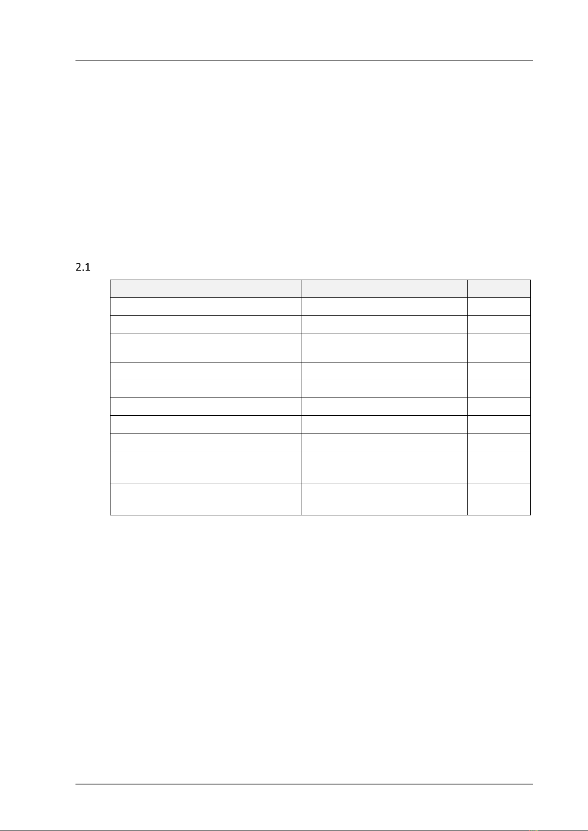
Technical specifications
Operating data
Nominal size
Unit
Own weight of control head
2,3
kg
Working load maximum:
75
kg
Possible goods to be transported:
Boxes, sacks, buckets, canisters,
drums, etc…
Lift tube diameter
⌀100, 120, 160
mm
Max. number of load cycles
20,000
Ambient temperature (operation)
+ 5 to + 45
°C
Ambient temperature (storage):
+15 to + 25
°C
Rel. air humidity (operation and storage)
max. 80 %
Vacuum pump: 230V/400V, 2,4KW
Vacuum blower: 400V, 3KW
Pump: VAL 50T, 80T,
Blower: SV400/2
Noise level
Pump: 56
Blower: 71
dB(A)

STRUCTURE AND FUNCTION
12/51 FORCE-LIFT®
Functional Description
The vacuum lifter consists of the following main components:
(1) Swivel joints with eyelet
(2) Lift tube
(3) Control head
(4) Suction foot
(5) Supply line
(6) Filter unit
(7) Motor protection
(8) Vacuum pump/blower
(9) Pillar-mounted slewing crane + jib
Functional description
The vacuum generator (8), pump or blower depending on the use, generates the air flow volume
and provides the vacuum. The vacuum or the generated air flow reaches the product to be
transported through the filter unit (6), via the supply line (5), the lift tube (2), the control head (3)
and then the suction foot (4).
If the suction foot is placed on the product to be transported, e.g. a cardboard box, the device
attaches itself. The external air, which previously streamed in through the suction foot, is
decreased or stops completely which in turn increases the vacuum in the entire system. With the
rapidly increasing vacuum, the previously untensioned lift tube starts to tighten. A spring is
integrated in the lift tube to ensure, among other things, that the lift tube does not implode due to
the vacuum. As soon as the lifting force (negative pressure x lift tube cross-section area) is greater
than the weight of the product to be transported, the product can be lifted.
Regulating the external air in the control head either raises or decreases the vacuum in the entire
system. Adding external air reduces the

LIST OF CONTENS
FORCE-LIFT®13/51
vacuum and thus causes the lift tube to expand lengthwise and the control head with the suction
foot and the product being transported to be lowered. Conversely, the vacuum increases with the
reduction of external air, which in turn causes the lift tube to be tensioned and contract in terms
of length - the control head with the suction foot and the product to be transported raises up.
Consequently, the product being transported can be held suspended in the air by stopping the
addition of external air to a certain extent.
Quick-change coupling, swivelling and rotating function
A quick-change coupling is available to ensure that the operator can change the suction foot in
seconds. The suction foot can also be swivelled manually by 90°.
There is also a 360° rotating function for turning the product being transported. This allows the
product to be rotated continuously.
Operator controls
(1) Quick release button
(2) Automatic unlock and suspend
function
(3) Regulating screw for transport
goods
(4) Lock mechanism quick-change
coupling
(5) 360° rotating function
(6) Lift/lower control button
The FORCE-LIFT®is operated with only one hand with the control head.
The load is lifted up using the “Lift/Lower” button (6). If it is released slowly, the load moves
downward again. The unlock button (2) must be pressed to unlock. It is used as a safety lock
mechanism for the lowering function. If it is released suddenly, the load stays at the selected
height.
The release button (1) is used to quickly and easily release the load from the suction foot (quick
release).

STRUCTURE AND FUNCTION
14/51 FORCE-LIFT®
With the regulating screw for the transport goods (3) it is possible to regulate whether air-tight or
porous materials are suctioned. If it is closed, it is possible to lift air-tight transport goods. To lift
heavy cardboard boxes, the screw has to be unscrewed some, while to lift sacks or bags it has to
be unscrewed completely.
The product to be transported can be rotated continuously using the 360° rotating function (5).
By actuating the 90° unlock button (6), the suction foot can be swivelled manually by 90°. This
means that cardboard boxes can be easily stacked, for instance.
Vacuum pump or blower is switched on and off using the power switch (not shown). Optionally,
the vacuum generators can be switched on and off via a remote control.
Safety devices
The release button (1) is protected against inadvertent actuation as a result of its position, the
required actuation force and the length of actuation.
The spring-return unlock button (2) must be pressed in order to actuate the button (7). When
actuating the button (7), the vacuum increases; while it decreases when the button is released,
provided that the unlock button (2) is pressed. If the control head is released suddenly, the unlock
button (2) closes very quickly, ensuring that the vacuum remains and that the vacuum lifter holds
the load at a constant height. This prevents the load from causing any personal injuries or property
damage when the control head is released.
A safety non-return valve (not shown) prevents a rapid drop in the vacuum in case of a power
failure and thus the load from falling. In case of a power failure, the vacuum is decreased and the
lift tube is slowly lowered.
LIST OF CONTENS
FORCE-LIFT®15/51
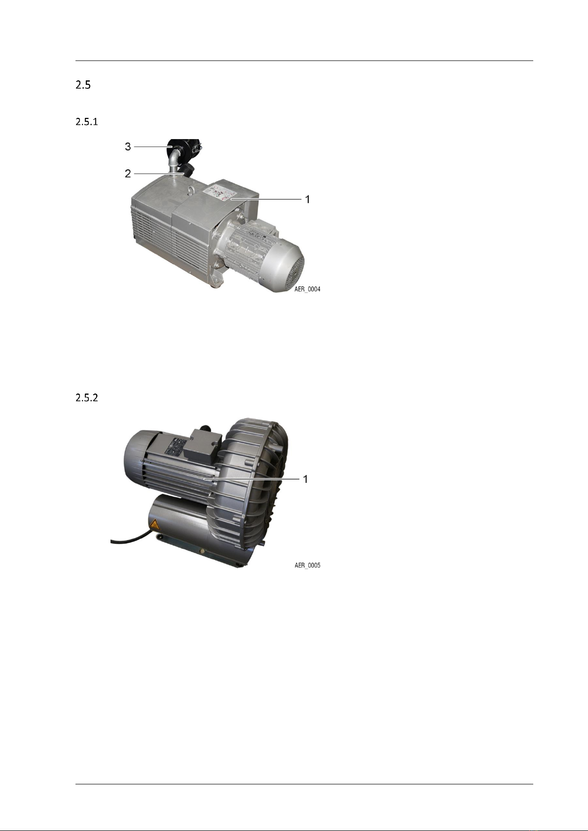
Components
Vacuum pump
(1) Vacuum pump
(2) Vacuum control valve
(3) Vacuum filter
The vacuum for the vacuum lifter is generated using the vacuum pump. The pump consists of a
vacuum pump (1) with rotation control (2) and an upstream vacuum filter (3). It is switched on and
off using a power switch (not shown).
The selection of the pump depends on the application. Pumps from 40 to 80 m³/h can be used.
See further applicable documents.
Vacuum blower
(1) Vacuum blower
The vacuum for the vacuum lifter is generated using the vacuum blower (1). The powerful blower
can be switched on and off using the power switch or a radio control.
See further applicable documents.
STRUCTURE AND FUNCTION
16/51 FORCE-LIFT®
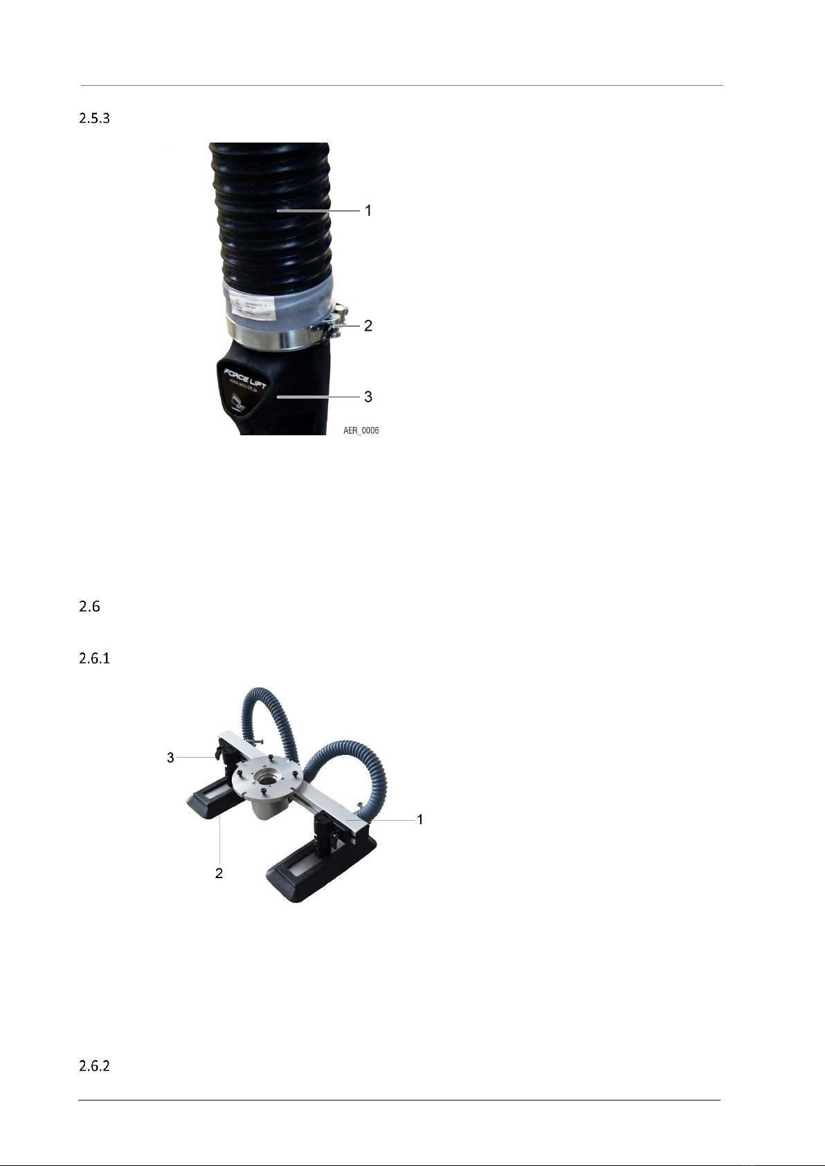
Lift tube
(1) Lift tube
(2) Clamp for fastening
(3) Control head
The lift tube (1) is used to raise, hold and lower the product to be transported. The lift tube is
suspended from a swivel joint with an eyelet on the crane. It is fastened to the control head (3)
with a clamp (2) on the bottom.
The lift tube rises when the vacuum is generated or increases and lowers when the vacuum
decreases. If the vacuum supply stops or the blower fails, it sinks slowly downward with the
product to be transported.
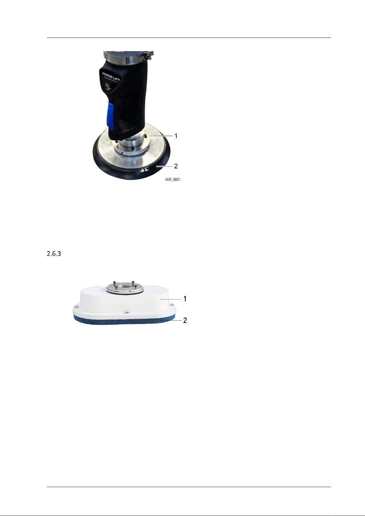
Suction feet (options)
Double rectangular suction foot
(1) Cardboard suction foot
(2) Suction plate
(3) Adjustment of suction foot
The card board suction food is an adjustable double-rectangular suction foot for transport goods
surfaces that are not inherently stable. It is mounted so that it can tilt and is specially designed for
handling boxes or steel plates and similar.
It consists of two suction plates (2). They can be adjusted in width with the adjustment (3) to adapt
to the width of the products to be transported.
Round suction foot
LIST OF CONTENS
FORCE-LIFT®17/51
(1) Base plate
(2) Seal
The barrels lifter is a suction foot for drums or barrels and other inherently stable or smooth
transport goods surfaces. It consists of a base plate (1) and a seal (2) that can be changed in just
a few seconds.
The suction cup-shaped design of the seal ensures an airtight seal with the surface of the product
to be transported.
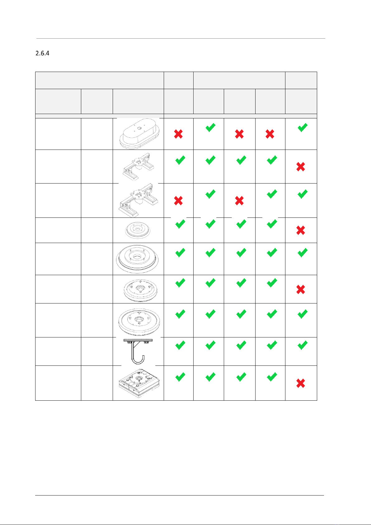
Bag suction foot
(1) Basic housing
(2) Seal
The bag suction foot is designed for handling bags and similar transport goods that are not
inherently stable and which do not have smooth surfaces. The bag suction foot consists of a basic
housing (1) and the circumferential seal (2).
The sponge-like design of the lower seal can compensate for unevenness in the surface of the
product to be transported.
STRUCTURE AND FUNCTION
18/51 FORCE-LIFT®
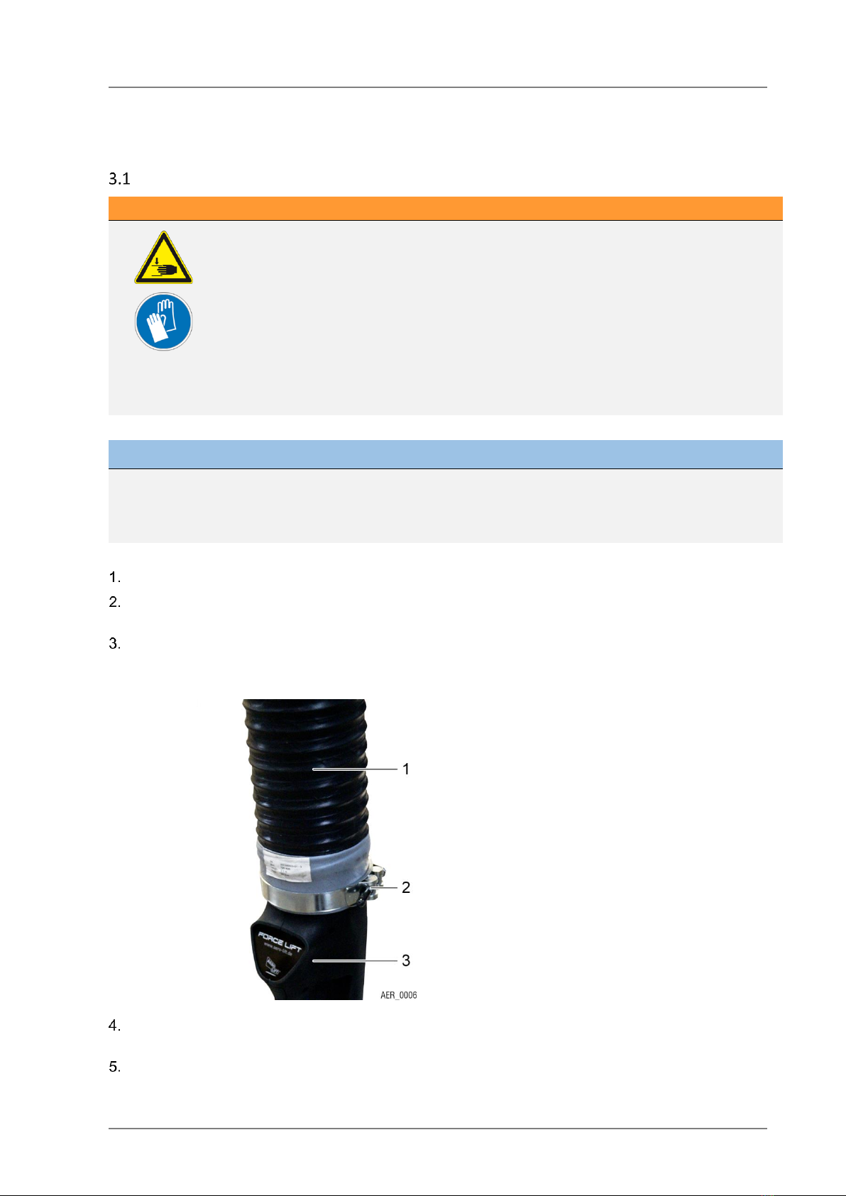
Suction foot and load capacity
Lifting tube:
Ø100
Ø120
Ø160
description
Article-
number
picture
VAL50T
SV400/2
VAL50T
VAL80T
SV400/2
bag suction
food
395x210mm
3080509
max. 25kg
at 25%
max. 50kg
at 30%
Double
rectangular
suction food
2x85x200mm
3089858
max. 20kg
at ca. 30%
max. 45kg
at 45%
max. 20kg
at 25%
max. 50kg
at 50%
Double
rectangular
suction food
2x110x300mm
3089900
max. 45kg
at 45%
max. 50kg
at 50%
max. 75kg
bei 60%
Round suction
food Ø210R
3089973
max. 40kg
at 60%
max. 60kg
at 60%
max. 60kg
at 60%
max. 60kg
at 60%
Round suction
food Ø270R
3089972
max. 40kg
at 60%
max. 60kg
at 60%
max. 60kg
at 60%
max. 60kg
at 60%
max. 75kg
at 60%
Barrel suction
food
Ø180T
3090113
max. 40kg
at 60%
max. 60kg
at 60%
max. 60kg
at 60%
max. 60kg
at 60%
Barrel suction
food
Ø220
3090109
max. 40kg
at 60%
max. 60kg
at 60%
max. 60kg
at 60%
max. 60kg
at 60%
max. 75kg
at 60%
Hook suction
food
3080511
max. 40kg
at 60%
max. 60kg
at 60%
max. 60kg
at 60%
max. 60kg
at 60%
max. 75kg
at 60%
VUSS
200x200mm
3014143
max. 20kg
at 30%
max. 45kg
at 45%
max. 20kg
at 30%
max. 45kg
at 45%
LIST OF CONTENS
FORCE-LIFT®19/51
3Installation
Installing the vacuum lifter
WARNING!
Moving parts!
Crushing of fingers / hands when moving or adjusting the position of the suction plates,
during maintenance work and mounting may lead to injuries.
✓Do NOT touch or reach between individual suction plates (double-rectangular
suction foot), quick-changing coupling and suction foot or between other
components!
✓Carefully install the vacuum lifter.
✓Do not remove the protective covers.
✓Always wear personal protective equipment when installing and making
adjustments!
NOTE
Placement of suction feet
Do not store or lay down the suction feet with the seal facing downwards! Placing the suction feet with
the seal facing down can damage the seals.
Unpack components of the vacuum lifter.
If necessary, mount on the crane to be used. Secure the vacuum lifter at the ends of the crossbeam
with safety screws, spring retaining pins or locking pins
Attach the vacuum supply line to the used crane or jib and connect to the vacuum pump or blower
via the filter unit. Do not yet connect the vacuum pump/ blower to the mains! Make sure that the
supply system eyelets have been fastened securely.
(1) Lift tube
(2) Fastening clamp
(3) Control head
Fasten lift tube (1) to the control head (3) using a hose clamp (2). To do so, pull the lift tube over the
upper end of the control head (3). Make sure that the closure is airtight!
Fasten the lift tube (1) to the cup with the ball bearing on top (suspension) in a positive-fit manner. In
this case, screw the wire spiral onto the groove. Make sure that the closure is airtight!

INSTALLATION
20/51 FORCE-LIFT®
Attach the desired suction foot to the control head. See section “Fastening/changing suction foot”.
Connect the vacuum pump/blower to the mains and start up the vacuum lifter. Use sound insulation
if necessary. See further applicable documents.
→Vacuum lifter was mounted.
NOTE
Vacuum pump/blower
For the start-up of the vacuum pump or blower, observe the information provided in the further applicable
documents!
Electrical connection
NOTE
Vacuum blower
When using an vacuum blower as a vacuum generator, the electrical fuse protection must be a C16 fuse.
Table of contents
Popular Lifting System manuals by other brands

probst
probst SDH-H-15 operating instructions

Bruno
Bruno OUTDOOR ELITE CRE-2110E Operator's manual

matev
matev FPS Mounting Assembly Installation Guide

Vestil
Vestil CYL-HLT Series instruction manual

Butts Tools
Butts Tools BXS0002 operating instructions

Safelift
Safelift MoveAround MA60 Original instructions


R. Beck Maschinenbau
R. Beck Maschinenbau HS 600 operating manual

Nova Technology International, LLC
Nova Technology International, LLC NAS Series quick start guide

Genie
Genie Z-60/34 Operator's manual

Screen Technics
Screen Technics INTERFIT Vertical Up Lift instructions

Drive
Drive DUPONT SAMERY Hermes user manual

Custom Equipment
Custom Equipment Hy-Brid 3 Series MAINTENANCE & TROUBLESHOOTING MANUAL