manuals.online logo
Brands
  1. Home
  2. •
  3. Brands
  4. •
  5. Protekt
  6. •
  7. Lifting System
  8. •
  9. Protekt AT 252 User manual

Protekt AT 252 User manual

800...
2000mm
420
max. 2470mm
590
Pillar "B"
Foldable
Beam
Pillar "A"
Wheel for
rope guidance
RUP502-T brake winch (for lifting loads)
sold separately
Concrete well
Foldable beam
Locking pin with spring Locking pin with spring
Beam arm with 9 pcs.
adjustment holes
Locking pin
for rope secure
Additional attachment
point under the wheel
DESCRIPTION
The AT 252 anchor beam is a portable anchor point. Beam can be used on the concrete wells of diameter from 800mm to
2000mm. Device can be used for lifting loads. Winch is equipped with automatic brake for load suspension.
Device consist of:
a) Foldable beam with cast iron wheel for working rope guidance.
b) Pillar "A" with plate for winch installation.
c) Pillar "B".
Brake winch RUP502-T (for lifting loads) sold separately.
Device is made of powder painted steel. Each Pillar is equipped with locking pin with spring for quick beam installation.
Foldable beam for easier transport consist of centrally installed wheel for working rope guidance and two arms with 9 pcs. of
locking holes for proper adjustment to the well. The beam in the working position is protected against accidental closing with
locking pins with spring. Attachment point under the wheel can be used for attaching additional equipment.
PARAMETERS
Working Load Limit (WLL): 500kg
•
Ability to install RUP502-T brake winch
•
Powder painted steel construction
•
Weight: ~24kg (without winch)
•
Shipping dimensions: 115x55x65cm
•
INSTRUCTION MANUAL
edition: 2/20.02.2015 en
READ CAREFULLY BEFORE
USE THE EQUIPMENT
ANCHOR BEAM FOR CONCRETE WELLS
EQUIPMENT FOR LIFTING LOADS
Reference
number:
AT 252
1/7
Pillar "A"
Plate for winch
installation
RUP502-T brake winch
without grip
Bolts from RUP502-T grip
RUP502-T BRAKE WINCH INSTALLATION
Remove grip from RUP502-T brake winch according to RUP5-2-T Instruction manual - "Removing the grip fo the
1.
RUP502-T device".
Install winch without grip to the plate on Pillar "A" using the same bolts and nuts.
2.
2/7
Arm
"a" "a"
Lock with spring Lock with spring
"b"
"c"
Properly folded beam
Pillar socket
Lock with spring
Beam arm
Beam locking position.
"d"
"e"
Beam arm
Pillar socket
Lock with spring
"d"
"e"
"f"
PREPARATION OF THE BEAM
Open both arms of the foldable beam - step "a".
1.
Pull back the locking finger - step "b", and fully open the arm - step "c". Locking finger should move back automatically.
2.
Repeat sequence for second arm.
To unlock the arm pull back the locking finger and close the arm.
3.
PILLAR'S INSTALLATION / ADJUSTING
Pull back locking finger installed on the bottom of the pillar socket - step "d".
1.
Insert beam arm to the desired depth and lock on one of the nine positions (locking finger should move
2.
back automatically) - steps "e" and "f".
To remove the arm from pillar pull back the locking finger and pull out the arm from the pillar socket.
3.
3/7
"g"
Pillar limiter Pillar limiter
Concrete well
All pillar limiters must be located on the outer side of the well.
Pillar limiter
Pillar limiter
Pillar limiter
Pillar limiter
"h"
"h" "h"
"h"
ANCHOR BEAM INSTALLATION ON THE CONCRETE WELL
Adjust pillars spacing so that the pulley was near the center of the concrete well - step "g".
1.
Pillar limiters should be located as close as possible to the outer well surface - step "h".
2.
"g"
4/7
Locking pin
"i"
Workin rope
Connector
Automatic brake
inside the cover
STOP
EXTEND
THE ROPE FROM
REEL WHEN THE
RED SIGN
APPEARS!
MAX
500 kg
Additional anchor point
for additional equipment
installation.
WORKING ROPE INSTALLATION
Remove locking pin from the top side of the pulley.
1.
Insert end of the rope with connector between pulley wheel and arm on the opposite side of the winch - step "i".
2.
Secure rope installed on the wheel with locking pin.
3.
CAUTION!
The lifting / lowering function is for lifting / lowering loads only. Do not use AT 252 anchor beam witch winch for a
•
rescue or a fall arrest purposes.
Always operate the winch with hand power and with crank included in the equipment only.
•
Before each use a thorough inspection must be carried out. Inspection must be carried out by a person using the
•
device. In the case of damages and malfunctions, the device should be withdrawn from use.
Nevel allow to full extension of the working rope from the winch reel. Keep at least three rope coils on the reel - it is
•
marked by a special safety sign which situated on the rope. Stop extend the rope from the reel when the safety sign
appears! Obligatory check the condition of the safety sign.
DEVICE LOAD CARRYING CAPACITY
The load hoisted by the AT 252 anchor beam may be connected to the end of the working rope and/or to the additional
attachment point.
Maximum operating load carrying capacity of the device is 500 kg.
5/7
a
b
c
d
e
f
g
h
CONTENT OF THE IDENTITY LABEL
a) Device type.
b) Model symbol.
c) Reference number.
d) Equipment only for lifting loads - notice.
e) Month and year of manufacture.
f) Serial number of the tripod.
g) Caution: read the manual.
h) Marking of the manufacturer or distributor of the tripod.
TRANSPORT
Device should be transported in packaging protecting it from damage or getting wet, e.g. bags made of impregnated fabric or in
steel / plastic / waterproof wooden cases or boxes.
MAINTENANCE AND STORAGE
When using the device, protect it against mechanical, chemical and thermal damage. Do not use a damaged or malfunctioning
device. Clean a dirty device with a damp cloth. Store the device indoors, away from moisture and sources of heat.
THE ESSENTIAL SAFETY RULES AND ESSENTIAL PRINCIPLES OF USE
- Device is used for lifting and lowering loads weighing up to 500 kg.
- This is not an emergency device for lifting people and it should not be used for this purpose.
- Do not use device contrary to its intended use.
- Do not lift loads over an area occupied by people.
- Do not change the device design, repair or replaceable elements included in the kit.
- Before each use of the device, carry out thorough inspection to check the device condition and proper operation. Carefully
check all elements, paying particular attention to any damage, excessive wear, corrosion, abrasion, cuts and malfunction.
- At least once a year, after 12 months of use the device should be withdrawn from use for a detailed interim inspection. The
inspection can be carried out by the person responsible in the workplace for the interim inspections of the protective equipment
and trained for this purpose. Periodic inspections can also be carried out by the equipment manufacturer or a person or a
company authorized by the manufacturer.
- Device must be immediately withdrawn from use if there is any doubt about the condition of the device or its operation. The
device may be readmitted for use only after a manufacturer's detailed inspection, and manufacturer's written consent for its use.
- Check the stability of the load attached to the cable, on which it is hoisted, to prevent accidental detachment of any of the
elements.
- The use of the this device with other devices (such as devices for lifting and lowering loads) must be in accordance with the
instruction for use of these devices.
- It is forbidden to use the kits in which the device is included, in which the operation of any component disrupts the operation of
other components.
- In case of any doubts as to the condition and usage of the device, please contact the manufacturer.
6/7
IDENTITY CARD
IT IS RESPONSIBILITY OF THE USER ORGANISATION TO PROVIDE THE IDENTITY CARD AND TO FILL IN THE DETAILS REQUIRED. THE IDENTITY
CARD SHOULD BE FILLED IN ONLY BY COMPETENT PERSON RESPONSIBLE FOR PROTECTIVE EQUIPMENT. THE IDENTITY CARD SHOULD BE FILLED
IN BEFORE THE FIRST USE OF THE EQUIPMENT. ANY INFORMATION ABOUT THE EQUIPMENT LIKE: PERIODIC INSPECTIONS, REPAIRS, REASONS OF
EQUIPMENT’S WITHDRAWN FROM USE SHALL BE NOTED. THE IDENTITY CARD SHOULD BE STORAGED DURING A WHOLE PERIOD OF EQUIPMENT
UTILIZATION. DO NOT USE THE EQUIPMENT WITHOUT THE IDENTITY CARD.
PRODUCER:
PROTEKT, 93-403 LODZ, ul. Starorudzka 9, POLAND, tel: +48 (42) 680 20 83, fax: +48 (42) 680 20 93, www.protekt.com.pl
.....................................................................................................................................................................................................
.....................................................................................................................................................................................................
.....................................................................................................................................................................................................
.....................................................................................................................................................................................................
.....................................................................................................................................................................................................
.....................................................................................................................................................................................................
MODEL AND TYPE OF EQUIPMENT
REF. NUMBER
SERIAL NUMBER
DATE OF MANUFACTURE
DATE OF PURCHASE
DATE OF FIRST USE
USER NAME
PERIODIC EXAMINATION AND REPAIR HISTORY
DATE
REASON FOR SERVICING /
REPAIR
REPAIRS CARRIED OUT
NAME AND
SIGNATURE OF
COMPETENT PERSON
DATE OF
NEXT
EXAMINATION
1
2
3
4
5
6
7
8
9
7/7

Other Protekt Lifting System manuals

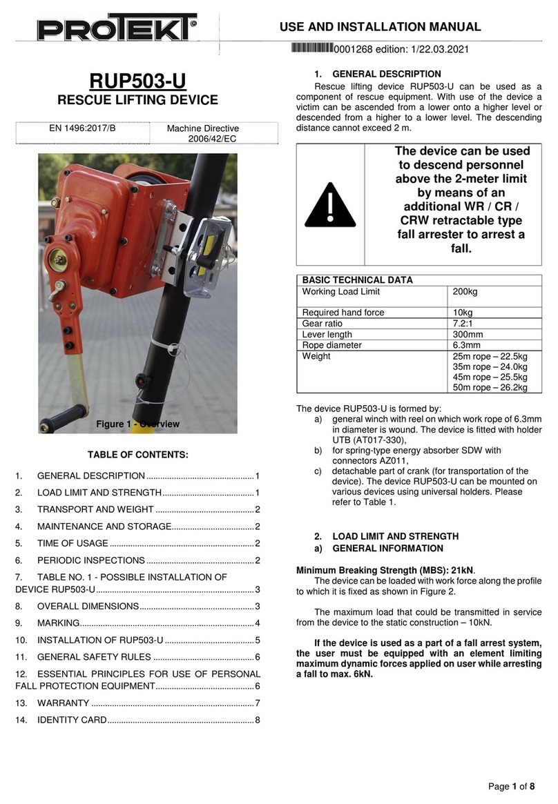
Protekt RUP503-U Technical specifications

Protekt

Protekt RUP503-U Technical specifications

Protekt AT 050 Series User manual

Protekt

Protekt AT 050 Series User manual

Popular Lifting System manuals by other brands

Asano AK10141 instruction manual

Asano

Asano AK10141 instruction manual

Ricon SLIDE-AWAY ST00 Service manual

Ricon

Ricon SLIDE-AWAY ST00 Service manual

MFC International Powermat product manual

MFC International

MFC International Powermat product manual

JLG 260MRT Operation and safety manual

JLG

JLG 260MRT Operation and safety manual

Bike-Lift HQL 400 Use and maintenance manual

Bike-Lift

Bike-Lift HQL 400 Use and maintenance manual

MSW MSW-HB-1500N user manual

MSW

MSW MSW-HB-1500N user manual

Ravaglioli KPH 370.42LLK Translation of the original instructions

Ravaglioli

Ravaglioli KPH 370.42LLK Translation of the original instructions

Rotary 100 Series Operation and maintenance manual

Rotary

Rotary 100 Series Operation and maintenance manual

Aqua Creek Products Revolution Deep Draft Lift manual

Aqua Creek Products

Aqua Creek Products Revolution Deep Draft Lift manual

Magliner CooLift CMH Series owner's manual

Magliner

Magliner CooLift CMH Series owner's manual

Braun FMVSS 403 quick reference

Braun

Braun FMVSS 403 quick reference

Haulotte Group star 6 Operator's manual

Haulotte Group

Haulotte Group star 6 Operator's manual

Skyjack SJIII 4740 operating manual

Skyjack

Skyjack SJIII 4740 operating manual

Black Widow BW-1500AO-V2 installation manual

Black Widow

Black Widow BW-1500AO-V2 installation manual

HADEF 20/94AF-EX Installation, Operating and Maintenance Instruction

HADEF

HADEF 20/94AF-EX Installation, Operating and Maintenance Instruction

PFlow Industries B Series Owner's, Installation and Maintenance Manual

PFlow Industries

PFlow Industries B Series Owner's, Installation and Maintenance Manual

GYS SPOT LIFT EASY Translation of the original notice

GYS

GYS SPOT LIFT EASY Translation of the original notice

Aqua Creek Products REVOLUTION LIFT SD SLING F-706RLSS manual

Aqua Creek Products

Aqua Creek Products REVOLUTION LIFT SD SLING F-706RLSS manual

manuals.online logo
manuals.online logoBrands
  • About & Mission
  • Contact us
  • Privacy Policy
  • Terms and Conditions

Copyright 2025 Manuals.Online. All Rights Reserved.