11
These inverters can conduct and radiate radio frequency energy and, if not installed and used in accordance with
the instruction manual, may cause harmful interference to radio communications.
REDUCING EMI THROUGH PROPER INSTALLATION The effects of EMI will also depend upon a number of
factors external to the inverter like proximity of the inverter to the EMI receptors, types and quality of connecting
wires and cables etc. EMI due to factors external to the inverter may be reduced as follows: - Ensure that the
inverter is firmly grounded to the ground system of the building or the vehicle - Locate the inverter as far away from
the EMI receptors like radio, audio and video devices as possible - Keep the DC side wires between the battery
and the inverter as short as possible. - Do NOT keep the battery wires far apart. Keep them taped together to
reduce their inductance and induced voltages. This reduces ripple in the battery wires and improves performance
and efficiency. - Shield the DC side wires with metal sheathing / copper foil / braiding: - Use coaxial shielded cable
for all antenna inputs (instead of 300 ohm twin leads) - Use high quality shielded cables to attach audio and video
devices to one another - Limit operation of other high power loads when operating audio / video equipment
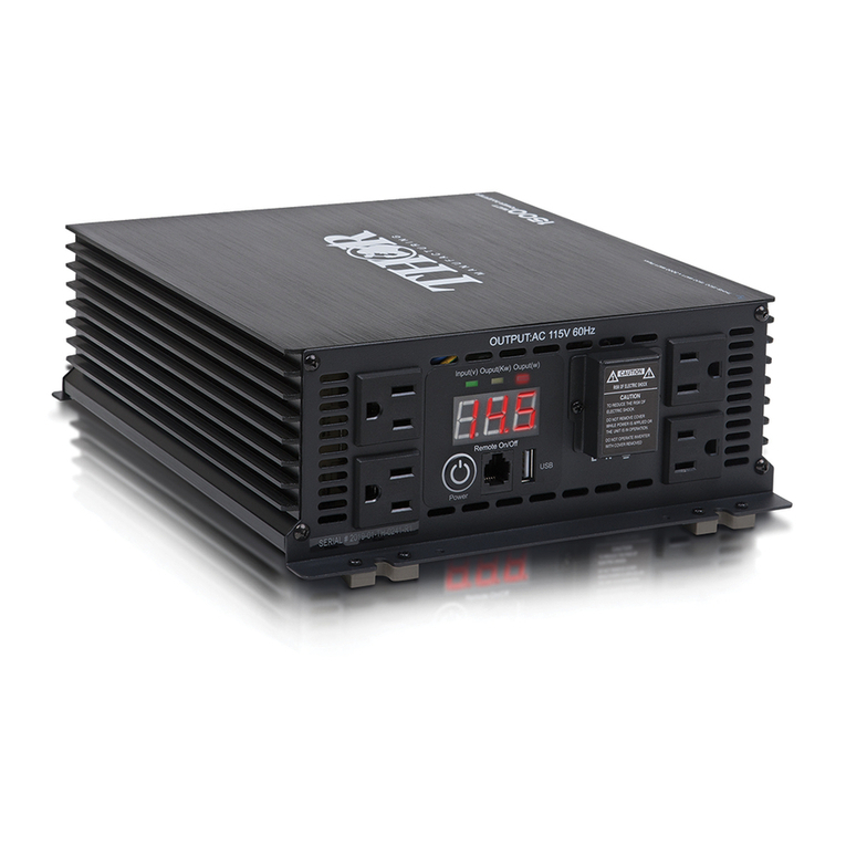
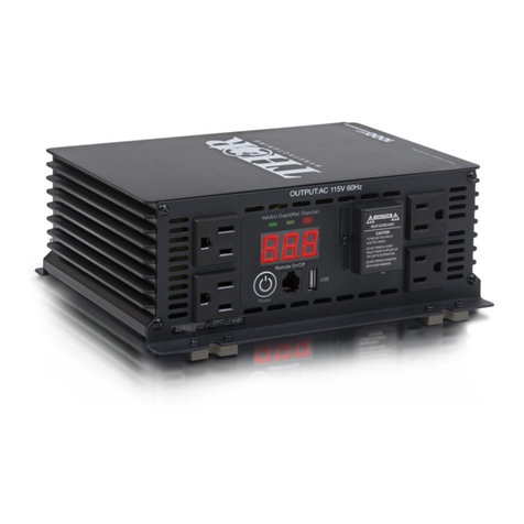
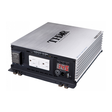
CAUTION. Each of the NEMA5-15P outlets is rated for 16A continuous and 20A intermittent. Do not draw more
than this rating from each outlet. For drawing the full rated output capacity of 25A of the inverter, use AC output
connections for hard wiring (13, Fig 6.1b) as described at Section 8.5.2 below. 2. Do not feed the output from the
GFCI receptacle to a Panel board / Load Center where the Neutral is bonded to the Earth Ground. This will trip the
GFCI. If the AC output is required to be fed to a Panel board / Load Center, use hard wiring connections. 3. If an
extension cord is used from the GFCI outlet, please ensure that the cord is suitable for the rated load and provided
with grounding.
AC Output Connections for Hard wiring For connecting the AC output of the inverter to an AC Panel board / Load
Center, separate connections are available for hard wiring Compartment contains terminals for AC output. The
compartment is covered by Cover Plate with the help of 4 screws. The AC wiring enters through the Strain Relief
Clamp . After the connections have been made, tighten the clamp. AC output connections are as follows: Terminal
Block with Line “L” and Neutral “N” Terminals. Please note that Line terminal “L” of the AC Terminal Block and the
Line terminal on the Line side of the GFCI are internally connected together at the PCB. Similarly, Neutral terminal
“N” on the AC Terminal Block and the Neutral terminal on the Line side of the GFCI are internally connected together
at the PCB. All external wiring should be in accordance with NFPA 70 / NEC and local wiring codes.
Grounding to Earth or to other Designated Ground For safety, ground the metal chassis of the inverter to the Earth
Ground or to the other designated ground (For example, in a mobile RV, the metal frame of the RV is normally
designated as the Negative DC Ground). A chassis Grounding Lug (19, Fig 6.1c) has been provided for grounding
the metal chassis of the inverter to the appropriate ground. When using the inverter in a building, connect a 10 mm2
or AWG #8 insulated stranded copper wire from the above equipment grounding lug to the Earth Ground connection
( a connection that connects to the Ground Rod or to buried metallic water pipe or to another connection that is
solidly bonded to the Earth Ground ). The connections must be tight against bare metal. Use star washers to
penetrate paint and corrosion. When using the inverter in a mobile RV, connect a 10 mm2 or AWG #8 insulated
stranded copper wire from the above Chassis Grounding Lug to the Main Grounding Bus Bar of the RV (bonded to
the vehicle chassis). The connections must be tight against bare metal. Use star washers to penetrate paint and
corrosion.
CAUTION. To Prevent fire, do not cover or obstruct ventilation openings. Do not mount in zero- clearance
compartment, Overheating may result.
OPERATING INSTRUCTIONS
CAUTION: Make sure the combined load requirement of your equipment does not exceed your inverter’s
maximum continuous power.
Operation of the 120 Volt AC Outlets
This unit features 115 volt AC GFCI (ground fault circuit interrupter) protected outlets, that function in the same way
as GFCI outlets you would typically use in your home. GFCI outlets are intended to protect equipment by
interrupting the circuit if current leakage exceeds 30 mA of current within 25 milliseconds.
1. Connect the inverter to a functioning 12 volt DC power source as described in this Instruction Manual. Make
sure there is adequate space for proper ventilation of the inverter.
2. Press the Power Push button to turn the unit ON.


