11.
Connection of the communication and control signals
12.
Commissioning
PVI-3.0_3.6_4.2-TL-OUTD-W-Quick Installation Guide EN-RevA
EFFECTIVE 2014-04-02
© Copyright 2014 ABB. All Rights Reserved.
9.
Line cable and protection devices
10.
Output connection (AC)
14.
Instruments
15.
Characteristics and technical data
13.
To protect the AC connection line of the inverter, we recommend installing a device for protection against over current and leakage with the following characteristics:
Type Automatic circuit breaker with differential thermal magnetic protection
Nominal Voltage 230 Vac
Nominal Current 20 A 25 A
Magnetic protection characteristic B/C
Number of poles 2
Type of differential protection A/AC
Differential sensitivity 300 mA
ABB declares that the ABB transformerless inverters, in terms of their construction, do not inject continuous ground fault currents and therefore there is no
due to high impedance of the line that connects the inverter to the power supply point.
2) Maximum length of the line conductor (mt)
4 mm² 19 m 16 m 14 m
6 mm² 29 m 24 m 21 m
10 mm² 48 m 41 m 35 m
16 mm² 77 m 65 m 56 m
The values are calculated in nominal power conditions, taking into account: 1. a power loss of not more than 1% along the line. 2. copper cable, with HEPR rubber insulation, laid in free air
Contact us
inverter has been correctly disconnected
- Remove the protective cap on the hole
19
used to pass the AC cable into the inverter.
-Insert an M32 cable gland (or compatible - hole diameter 33.8 mm) in the hole to be used for the AC output cable
19
- Strip 10 mm of sheathing from the AC grid connection cables
- Plug the AC line cable into the inverter, passing it through the previously installed cable gland
- Connect the protective earth (yellow-green) cable to the contact labelled with the symbol on the terminal block
10
section of the conductor for the maximum ground fault current that the generating system might experience
- Connect the neutral cable (normally blue) to the terminal labelled with the letter N
- Connect the phase cable to the terminal labelled with the letter L
Once the connection to the terminal board
10
Each cable which must be connected to the connectors of the communication and control signals must pass through one of the two service cable glands
20
.
An M20 cable gland (or compatible – hole diameter 20.3 mm) must be inserted in one of two of the service cable glands holes
20
.
Connection of the tachometer signal
The tachometer signal allows the 7200-WIND-INTERFACE-EU to drive the inver-
ter. It is therefore necessary to connect up the two cables from the 7200-WIND-
INTERFACE-EU ( and ) to the tachometer signal
terminal block
13
in correspondence with terminals and .
14
and by the terminal block
13
) must necessarily be connected to the
7200-WIND-INTERFACE-EU. For further details on connection of the RS485
line please see the 7200-WIND-INTERFACE-EU manual.
Terminal block
13
SET
TINGS > Alarm
that can be set are: Production and Alarm.
to the DC input voltage)
The REM terminal block
13
manual
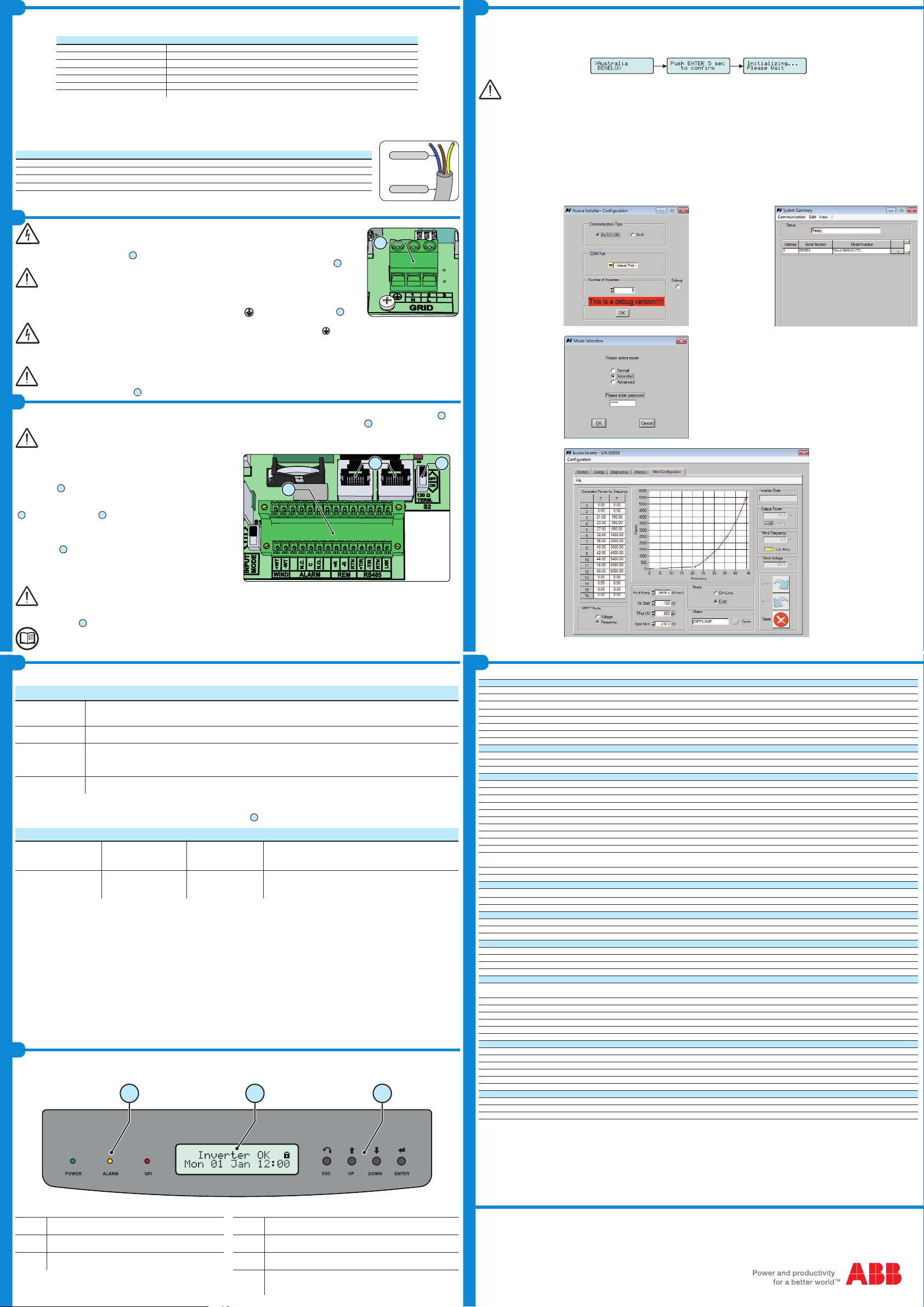
The inverter commissioning procedure is as follows:
- Close the external switches: If the input voltage is greater than the minimum starting voltage, the inverter will start up.
- -
Select.” functionality will be blocked, and any subsequent changes can only be made using a password provided on request by ABB
Loading the Power Curve of eolic generator
not yet been loaded into the inverter. Thus, before connecting the inverter into the power grid, you must load the curve using the Aurora Installer software.
Follow the following step-by-step procedure for upload the power curve:
-
- Install the Aurora Installer application on your PC
-
voltage, provided it can produce at least 50V
- Connect the inverter to your PC using the PVI-USB-RS485_232 converter (for details of the connection, see the PVI-USB-RS485_232 converter manual)
- Launch the Aurora Installer application
1. In the
ration” window select
the COM port from the
pull-down menu, enter
the number of inverters
you have connected to
the PC and click OK.
2. The application will
scan the communica-
tion line looking for the
connected inverters. The
discovered inverters will
be displayed in a table.
Click to select the
inverter you want to
work with.
3. In the
lection” window select
and enter
the following password:
05591. Then click OK.
4. Go to the
tab: the
application will read the
power curve table in the
inverter (this will happen
even if no table has yet
been loaded, in which
case no curve will be
shown in the graph);
5. From mode
go to mode to
compile the power curve
-
ble for information about
compiling the power
curve) Alternatively, to
created previously, click
and select the
6. From mode go to
mode again and click
to send the table to the
inverter.
same curve to more than one
As” to export the curve to your
PC in .mpp format so that it is
available for other inverters.
The following parameters must be provided, with the power curve, by turbine’s manufacturer. See table below for more details about the parameters:
Output Power Ramp
(Pout Ramp)
The value must be between 275 W/sec and 10,000 W/sec. In the commissioning phase of the system, if an instability is detected, try
Inverter Activation
Voltage (Vin Start) This is the input voltage above which the inverter connects to the grid. The value must be between 50V and 200V.
Undervoltage
protection time
(Tprot UV)
-
gy again to the grid whenever the wind pickups, without having to repeat the inverter start-up process. The value must be between 1
sec and 3600 sec.
Nominal Grid Voltage
(Vgrid Nom) Indicates the rated voltage of the grid to which the inverter is connected.
-
show various messages on the display and change the behaviour of the three LED
06
:
INPUT VOLTAGE LED STATUS
Vin < Vstart Waiting Wind
Green = FLASHING
Yellow = OFF
Red = OFF
Vin > Vstart Missing Grid
Green = FLASHING
Yellow = ON
Red = OFF
the inverter waits until there is grid voltage to carry out the parallel
connection.
inverter to start up.
-
grid voltage check, measures the wind power system insulation resistance against earth and carries out other self-diagnosis checks. During the checks before
During the grid voltage check and measurement of the insulation resistance, the values for the grid voltage and frequency and the insulation resi
meet the ranges provided for by the regulations in force and if the insulation resistance is greater than 1Mohm.
- If the preliminary checks for parallel connection to the grid are successful, the inverter connects to the grid and begins to export power to the grid. At this stage,
the display shows the inverter’s parameters in cycles. The green LED stays lit whereas the others are off.
LEDs and BUTTONS, in various combinations, can be used to view the status or carry out complex actions that are described more fully in the manual.
080706
LED
On if the inverter is working correctly. Flashes when
ESC It is used to access the main menu, to go back to the previous menu
or to go back to the previous digit to be edited
LED
The inverter has detected an anomaly. The anomaly
is shown on the display.
UP It is used to scroll up the menu options or to shift the numerical scale
in ascending order
LED
GFI
Ground fault on the DC side of the PV generator. The
error is shown on the display.
It is used to scroll down the menu options or to shift the numerical
scale in descending order
selected option (indicated by the > symbol) or to switch to the next
digit to be edited
Input
Absolute Maximum Input Voltage (Vmax,abs) 600 V
Input Activation Voltage (Vstart) 50 V (adj. 50...350 V)
Input Operating Range (Vdcmin...Vdcmax)50...580 V
Input DC Voltage Range (Vmin,f ... Vmax,f) at Pacr 160...530 V 120...530 V 140...530 V
Maximum DC Input Current (Idc max)20.0 A 32.0 A 32.0 A
Maximum Input Short Circuit Current 25 A 40.0 A 40.0 A
Maximum Backfeed current (from AC to DC side) Negligible
DC Connection Type Screw terminal block
Input protection
Reverse Polarity Protection Yes, from limited current source
Input Overvoltage Protection - Varistor 2
Photovoltaic Array Isolation Control According to local standard
Output
AC Grid Connection Type Monophase
Rated AC Power (Pacr) 3000 W 3600 W 4200 W
Maximum AC Output Power (Pac max)3300 W (1) 4000 W (2) 4600 W (3)
Rated AC Grid Voltage (Vacr) 230 V
AC Voltage Range 180...264 Vac (4)
Maximum AC Output Current (Iac max)14.5 A 17.2 A (5) 20.0 A
Inrush Current Negligible
Maximum Output Fault Current <25 A rms (100mS)
r)
min...fmax)(6)
Nominal Power Factor (Cosphiacr) >0.995 adj. ± 0.9 with Pacr=
3.0 kW
>0.995 adj. ± 0.9 with Pacr=
3.6 kW
>0.995 adj. ± 0.9 with Pacr=
4.2 kW
Total Harmonic Distortion of Current < 3.5%
AC Connection Type Screw terminal block
Output protection
Anti-Islanding Protection According to local standard
Maximum AC Overcurrent Protection 16.0 A 19.0 A 22.0 A
Output Overvoltage Protection - Varistor 2 (L - N / L - PE)
Operating performance
max) 96.8%
Power Input Treshold 10.0 W
Stand-by Consumption < 8.0 W
Communication
Wired Local Monitoring PVI-USB-RS232_485 (opt.)
Remote Monitoring WIFI LOGGER CARD (opt.), PVI-AEC-EVO (opt.), VSN700 Data Logger (opt.)
Wireless Local Monitoring WIFI LOGGER CARD (opt.)
User Interface LCD Display with 16 characters x 2 line
Environmental
Ambient Temperature Range -25...+60°C /-13...140°F with
derating above 50°C/122°F
-25...+60°C /-13...140°F with
derating above 55°C/131°F
-25...+60°C /-13...140°F with
derating above 50°C/122°F
Storage Temperature -40...80°C (-40...+176°F)
Relative Humidity 0...100% condensing
3
Noise Emission < 50 dB(A) @ 1 m
Maximum Operating Altitude without Derating 2000 m / 6560 ft
Environmental Category External
Physical
Environmental Protection Rating IP 65
Cooling Natural
Dimension (H x W x D) 618 x 325 x 222 mm / 24.3 x 12.8 x 8.7 inch
Weight 17.5 kg / 38.6 lb
Mounting System Wall bracket
Overvoltage Category in accordance with IEC 62109-1 II (DC input) III (AC output)
Safety
Isolation Level Transformerless (TL)
Safety Class I
Marking
1. Limited to 3000 W for Germany
2. Limited to 3600 W for Germany
3. Limited to 4200 W for Germany
5. Restricted to 16 A (up to the maximum output power of 3680 W) for the standard UK G83/1.


