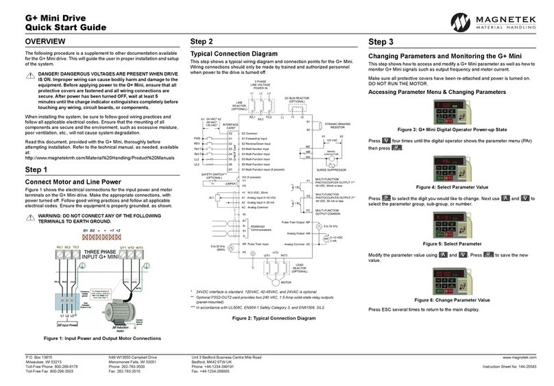
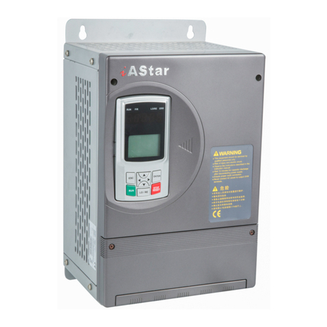
AeroDiode Cool & Control Series User manual

AERODIODE - Institut d’optique d’Aquitaine - Rue François Mitterrand
33400 Talence - France - Tél.: +33 (0)6 27 69 41 62
www.aerodiode.com
Operating manual
Cool & Control Series
CCMI Integrated multimode laser diode driver

Page 2/26 –v1.0
Contents
1. General information ............................................................................................................... 3
1.1. Definitions....................................................................................................................... 3
1.2. Laser hazard and general warning.................................................................................. 3
2. Safety Instructions .................................................................................................................. 5
2.1. Wiring.............................................................................................................................. 5
2.2. Operating Environment .................................................................................................. 5
2.3. Contact............................................................................................................................ 5
3. Fiber optic cleaning................................................................................................................. 6
4. Product overview.................................................................................................................... 7
4.1. Physical properties*........................................................................................................ 7
4.2. Ports description............................................................................................................. 7
5. Getting Started...................................................................................................................... 11
5.1. Installation .................................................................................................................... 11
5.2. Software overview........................................................................................................ 13
5.3. Setting the limits........................................................................................................... 16
5.4. Current and voltage adjustments ................................................................................. 16
5.5. Control mode................................................................................................................ 17
5.6. CW/pulse operation...................................................................................................... 17
5.7. Settings.......................................................................................................................... 18
5.8. Measurements.............................................................................................................. 19
5.9. Alarms ........................................................................................................................... 20
5.10. Menu bar....................................................................................................................... 21
6. Configuration examples........................................................................................................ 22
6.1. How to run the laser in CW/pulse mode with the GUI*............................................... 22
6.2. Use of optional TOMBAK to generate full adjustable pulses ....................................... 23
7. Technical specification.......................................................................................................... 26
7.1. General Data ................................................................................................................. 26
7.2. Detailed data................................................................................................................. 26

Page 3/26 –v1.0
1. General information
Please read this manual carefully, it describes the hazard the user might be exposed to while
using the product. It also explains in details how to use the product in the safest and more
efficient way possible.
The safety of any system incorporating the product is the responsibility of the assembler of the
system.
Any actions taken by the user that is not clearly described in this user manual might present a
risk and is the sole responsibility of said user.
This product is to be used in laboratory or industrial tasks, and only by personnel who have
followed a training in laser hazard.
1.1. Definitions
Caution : A caution is advised when dealing with hazardous situations, tasks or objects, to prevent
harm or death and avoid material damage or failure.
Warning : A warning is given for potentially dangerous situation for people which cause them
harm or lead to death
Note : A note is a complementary piece of advice that must be acknowledged by the user.
1.2. Laser hazard and general warning
WARNING
The compatible laser diodes used with the CCMI can deliver up to several Watts of coherent
LASER radiation. This product contains a CLASS 4 laser. Always wear protective goggles and
observe the safety instructions with respect to laser radiation directive (2006/25/CE).

Page 4/26 –v1.0
WARNING
Closing the software or removing the USB cable between the product and the PC do not stop
the laser emission.
To stop the laser emission, open the interlock or disconnect the power supply of the CCMI.
WARNING
Operating the CCMI with respect to laser radiation directive (2006/25/CE) is the responsibility of
the owner of the system and the product should not be put in operation before the machine or
system in which it will be integrated has been declared to be compliant with the relevant
requirements (NF EN 60825-1).
WARNING
Do not try to open or remove the cover of the CCMI module.
WARNING
Avoid all chocs and strains when handling the CCMI.
WARNING
Handle the fiber-optics cable with care as it is fragile. Do not bend or pinch it.
WARNING
Any software settings or hardware tinkering that is not described in this user manual or in the
usage recommendation may put the user or its environment at risk.
WARNING
The maintenance and servicing of the CCMI should not be executed by the end user : only
AERODIODE is able to maintain the CCMI.
Note
Only use the supplied USB cable.

Page 5/26 –v1.0
2. Safety Instructions
2.1. Wiring
Caution
-Please use cable of length inferior to 3m to power the CCMI in order to avoid EMC
compatibility (according to IEC61326-1)
-Please first connect the input pins to the board and then plug the 24V DC Power Supply
-Make sure that the pins are correctly screwed in
-Use caution when connecting the Power Supply
-Protect the power cord from being walked on or pinched particularly at plugs,
convenience receptacles, and the point where they exit from the CCMI module
2.2. Operating Environment
Caution
-Do not install near any heat sources such as radiators, heat registers, stoves, or other
equipment (including amplifiers) that produce heat.
-To reduce the risk of fire or electric shock, do not expose the CCMI to rain or moisture.
WARNING
Not following the safety recommendations and the caution mentioned above can lead to eye
damage.
2.3. Contact
If you have any question about the CCMI module, please contact AERODIODE.

Page 6/26 –v1.0
3. Fiber optic cleaning
The optical path after the connector must be completely under control before laser activation.
Please remove the power supply and the interlock of the product before each disconnection.
Always place the protective cap when the fiber is not connected to any accessory.
Before connecting the fiber, the end face must be cleaned.
If the end face is not clean, there is a risk of deterioration, permanent damage of the product
with loss of power and burn connector.
During the connector cleaning operation, make sure that laser emission is not possible (remove
the power supply and the interlock).
To clean the connector output, use a clean optical paper and acetone solution. Fold the optical
paper to make a rectangle and put acetone on it. Then place the end-face of the connector in
contact with the optical paper with a perpendicular position to the paper (you can rotate the
connector on the paper but don’t scrub the connector on the paper).

Page 7/26 –v1.0
4. Product overview
4.1. Physical properties*
4.2. Ports description
1. 24 Vdc / 10 to 40 A Power IN
Power supply location for the CCMI device (24 Vdc / up to 40A*)
*depends on laser diode power
2. Power ON indicator
Product
Length(mm)
Width(mm)
Height(mm)
Weight(kg)
CCM 60W
232
92
92
2.7
CCM 120W
240
120
123
4.7
CCM 200W
320
120
123
5.8
CCMI 30W
232
123
135
3
CCMI 70W
240
155
162
5.1
CCMI 180W
320
155
188
6.5
CCMI 100W + TOMBAK
240
180
162
6.7
* The values stated are some examples of CCM/CCMI configurations. For any other configuration, please contact AERODIODE for
more information. For the TOMBAK option, you have to add 25mm on the width.
1
2
3
4
5
6
7
8
9
10
11
12

Page 8/26 –v1.0
Blue LED indicates that the device is powered
3. Alarm indicator
Red LED indicates that an extreme condition is reached and has triggered the laser extinction
(Interlock open, CPU dysfunction or overheating)

Page 9/26 –v1.0
4. USB input
3.5 mm input jack used to connect the CCMI driver to the PC. Use the specific USB cable supplied
with your device
5. Daisy output
3.5mm output jack used to chain multiple CCMI drivers or any other device from the AERODIODE
line (CCMI, Central, CCS)
6. Photodiode 1 input [left: signal / right : GND]
Input connector for a first photodiode entrance signal. This signal is used for the Automated
Power Control mode (APC)
7. Photodiode 2 input [left: signal / right : GND]
Input connector for a second photodiode entrance signal (provision)
8. Interlock [left: signal / right : GND]
Connector interlock that must be shunted or connected to any interlock security system of the
machine/installation in order to allow laser activation and thermal regulation. The signal is a 3.3V
DC pull-up signal that must be grounded in order to allow emission.
9. Alarm output [left: signal / right : GND]
Output connector for alarm status monitoring (power, current, temperature) (low level indicates
alarm)
10. Monitoring electronic component temperature
Allows temperature monitoring when using the device on external monitoring mode (25°C
corresponds to 1.125 V) [left: signal / right : GND]
11. Monitoring current
Allows current monitoring when using the device without the software (185 mV/A)
[left : signal / right : GND]
12. Analog 0-2.5 V signal input for Ext Mode
Set here the relative laser diode current using a 0-2.5V signal input when CCMI has been
previously set in “Ext-Mode” in the “Current Source” panel of the software (the operating mode
should be kept to CW).
This signal could be used to make a current modulation (continuous, modulated or pulsed).
0 V = Minimum current
2.5 V = Maximum current

Page 10/26 –v1.0
•Left : Reserved
•Middle Left : Analog voltage input 0-2.5V
•Middle : Reserved
•Middle right : Reserved
•Right : Ground

Page 11/26 –v1.0
5. Getting Started
5.1. Installation
Caution
The CCMI USB specific cable should be unplugged during the installation.
Note
Please note that the USB cable can also be unplugged after the board has been configured.
Double-click on setup.exe to run the installer. The control software will be installed, as well as
the driver for the USB cable. A computer restart may be required to complete the installation.
- When the setup is completed, plug the USB cable into one of your computer’s USB port.
- Then plug-in the 3.5 mm jack into the USB input of the CCMI.
- If you have several CCMIs or other AeroDIODE electronic modules, you can connect them
together on a unique USB port by chaining them :
- Finally, connect the product to a 24 Vdc power supply.
CCM3
or
other
product
etc…
USB / Daisy in
Daisy out
USB / Daisy in
USB / Daisy in
Daisy out
CCM1
CCM2
USB port

Page 12/26 –v1.0
WARNING
Use adapted electrical wires that can handle enough current to connect the CCMI to the
power supply.
Click on the “ALPhANOV Control Software” item located in the Start Menu in order to run the
CCMI control software.
A window appears:
Click on Connect to start the CCMI hardware detection. The software automatically detects any
USB-connected AeroDIODE devices.
A window will appear for each CCMI driver connected to the computer.

Page 13/26 –v1.0
5.2. Software overview

Page 14/26 –v1.0
Controls
Max. level
Parameters
Laser
Enable
Measurements
Alarms

Page 15/26 –v1.0
The window is split in six parts:
1. MAX LEVELS: The maximum current and voltage values are settable in the Max levels part
and must be chosen in accordance to the laser diode specifications and operating data
everytime a new laser diode is mounted on the CCMI module (see bellow). The floppy
disk logo indicates that these values can be stored into the CCMI memory (upon clicking)
2. LASER ENABLE: The On/Off toggle button enables or disables the laser emission
3. CONTROLS: Toggle buttons in the Control part are used to select the operating mode.
4. SETTINGS: is used to configure diode current/voltage, laser slope, and laser temperature.
5. MEASUREMENTS: The Measurements area displays real time data, such as the
temperature measured by thermistors, or current and voltage values of diodes and
thermoelectric coolers.
6. ALARMS: The Alarms part shows if any element is or not causing a dysfunction.

Page 16/26 –v1.0
5.3. Setting the limits
The CCMI laser diode driver includes hardware overcurrent and overvoltage protections
requiring to be set up before to drive any laser diodes.
Please mind to configure these values to their maximums as recommended by the laser diode
supplier.
•As Max Current : Set laser diode nominal current + 10%
•As Max Voltage : Set laser diode nominal voltage + 2V
For example: If the laser diode has the following nominal levels:
•P = 60 W
•I = 12.1 A
•V = 13.4 V
Then you should set:
•Max current = 12.1 × 1.10 =𝟏𝟑.𝟑𝐀
•Max voltage = 13.4 + 2.0 = 𝟏𝟓. 𝟒 𝐕
5.4. Current and voltage adjustments
These two-position switches control the current and voltage sources.
Internal/External current source
In External mode an analog signal could be applied in “Side
connector input”to change externally the laser current (see details
in point 12 of Page 9). It could be used for continuous, modulated
or pulsed operation
Manual/Automatic voltage adjustment (user value or software
algorithm)
Automatic Voltage adjustment mode is recommended when using <100W laser diodes total
power

Page 17/26 –v1.0
5.5. Control mode
This two-position switch controls the operating mode (current or power control)
Direct Current Control / Automatic Power Control
Save the photodiode signal level for the constant power mode (see
Page 9)
5.6. CW/pulse operation
This two-position switch controls the operating mode (CW or pulse).
Select if the laser diode is operated continuously (CW) or pulsed
A new window will pop up on click: pulse settings
•Frequency: defines the pulse repetition rate
•Pulse width: defines the pulse width

Page 18/26 –v1.0
•Pulse Mode: if set to Internal, the pulse trigger is provided by the CCMI
hardware. External is not available at this time
•Gate Mode: if set to None, the CCMI laser driver will deliver pulses while the
laser is enabled. If set to Soft, the laser emission will stop after reaching the
burst count.
•Burst Count: number of pulses in Soft Gate Mode (1-255 range)
•Trigger: in Soft Gate Mode, the laser emission will begin upon clicking this
button
For the example displayed in the window, a single pulse (width=10ms) is emitted when
the user clicks on Trigger. If the burst count is set to 2, an additional pulse will be
emitted 500ms (2 Hz) after the first pulse (same pulse width).
5.7. Settings
Set the laser diode curent
Set the laser diode voltage
Set the laser diode current slope time (rise time)
Set the laser diode temperature
These values have to be defined carefully depending on various parameters fixed by the laser
diode supplier. Excessive parameters could trigger alarms or even lead to permanent damage
to the laser diode.
In case of Manual Voltage adjustment, set voltage ~1-1.5 V above desired laser diode voltage.

Page 19/26 –v1.0
5.8. Measurements
Indicates the current passing through the laser diode
Indicates the laser diode voltage
Indicates the laser diode temperature measured by the
mobile CTN.
A negative value indicates that the CTN is disconnected
Indicates the electronic temperature measured by a CTN
placed on a sensitive electronic component.
A negative value indicates that the CTN is disconnected.
If this value goes higher than 50°C, please lower the diode
voltage consign
Indicates the current passing through the TEC
Indicates the total voltage applied to the TEC
Indicates the Photodiode 1 voltage
Indicates the Photodiode 2 voltage

Page 20/26 –v1.0
5.9. Alarms
Red light indicates that the laser diode temperature has
crossed over the maximum value (default is 45°C).
Orange light indicates that the CTN cable is disconnected
Red light indicates that a sensitive electronic component
has reached a critical high temperature.
Orange light indicates that the CTN cable is disconnected
Red light indicates that the chosen voltage differs from
the diode’s nominal voltage.
Red light indicates an issue with the temperature
regulation.
Red light indicates a power supply issue (voltage drop for
example). The device’s red Alarm LED is triggered too.
Red light indicates an absence of Interlock or overheat
issue
Red light indicates that the APC signal from Photodiode 1
is above the threshold value
Other manuals for Cool & Control Series
1
This manual suits for next models
7
Table of contents
Popular DC Drive manuals by other brands
Erreka
Erreka Dolfin Quick installation and programming guide
Leadshine Technology
Leadshine Technology 3DM2283 user manual

Pro-dig
Pro-dig T20K instruction manual

Advantech
Advantech Automation1 iXC4e Hardware manual

Bosch
Bosch REXROTH IndraDrive Mi KSM01 operating instructions
Leadshine Technology
Leadshine Technology DM542E user manual
