RoHS
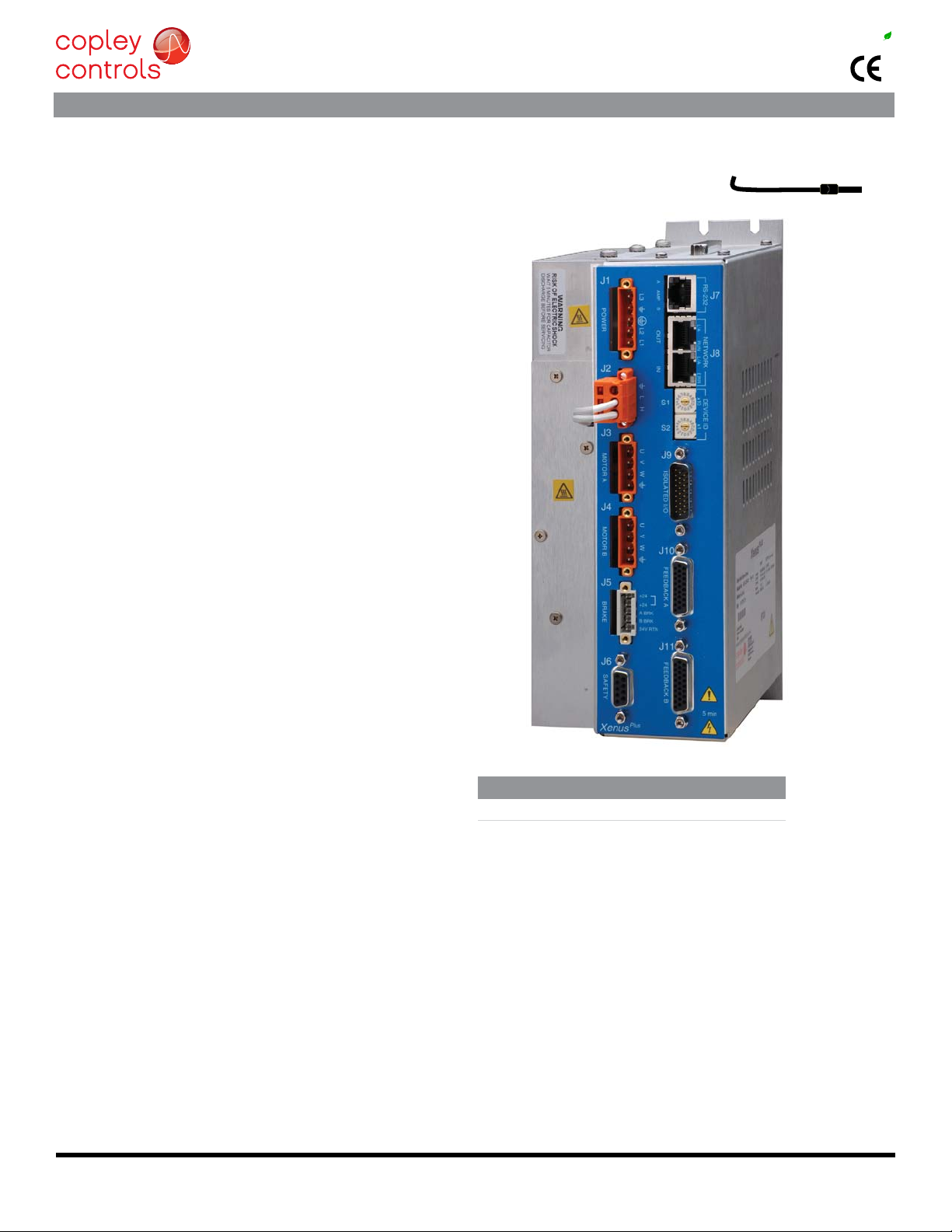
Xenus
PLUS 2-Axis
MACRO
XM2
Rev 01
Copley Controls, 20 Dan Road, Canton, MA 02021, USA
16-01419 Rev A Page 2 of 34
GENERAL SPECIFICATIONS
MODEL XM2-230-20
OUTPUT CURRENT () 0~40 C Ambient
Control power +24 Vdc, ±10% Required for operation
Digital Control Loops Current, velocity, position. 100% digital loop control
Sampling r
Bus voltage compensation Changes in bus or mains voltage do not affect bandwidth
Minimum load inductance
Distributed Control Modes
MACRO Velocity, Torque
Stand-alone mode
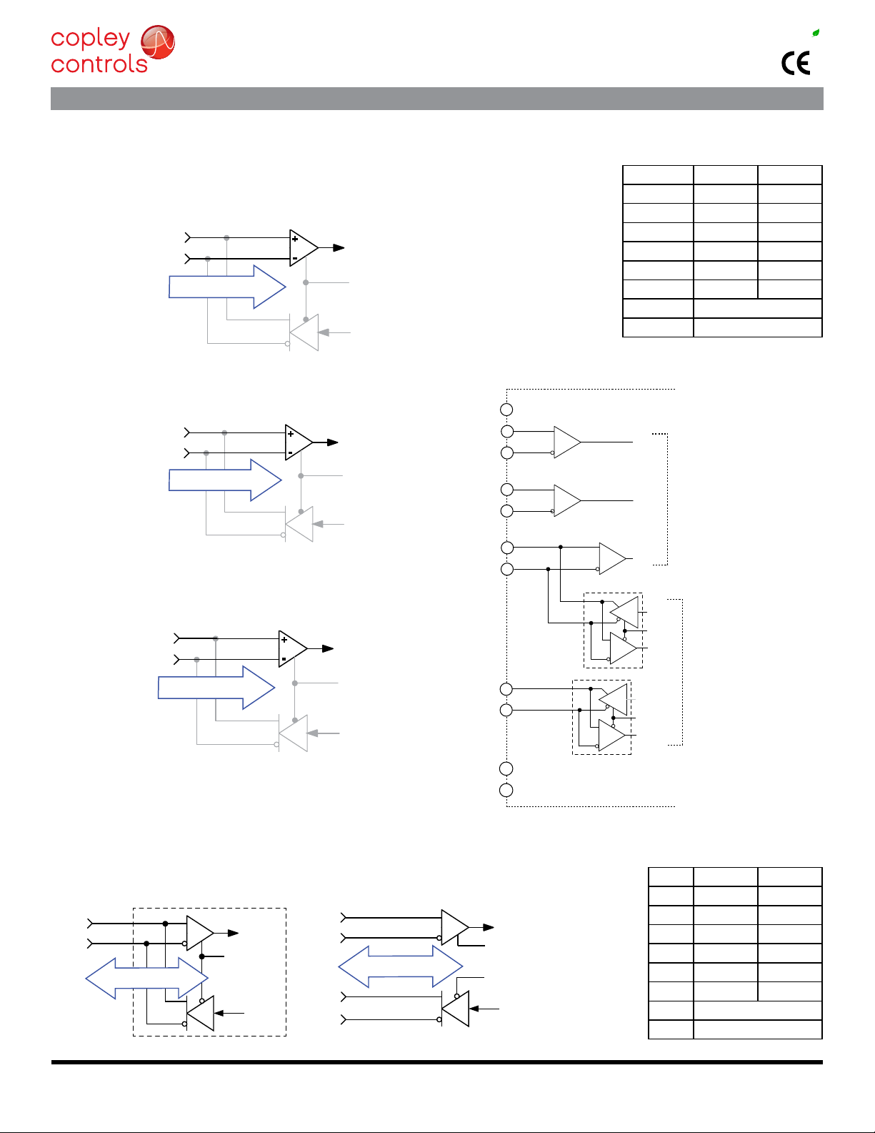
Analog torque, velocity, position reference ±10 Vdc, 14 bit resolution Dedicated differential analog input
Number 22
Ω
Ω
Ω
Number 2
Ωinput impedance, 14-bit resolution
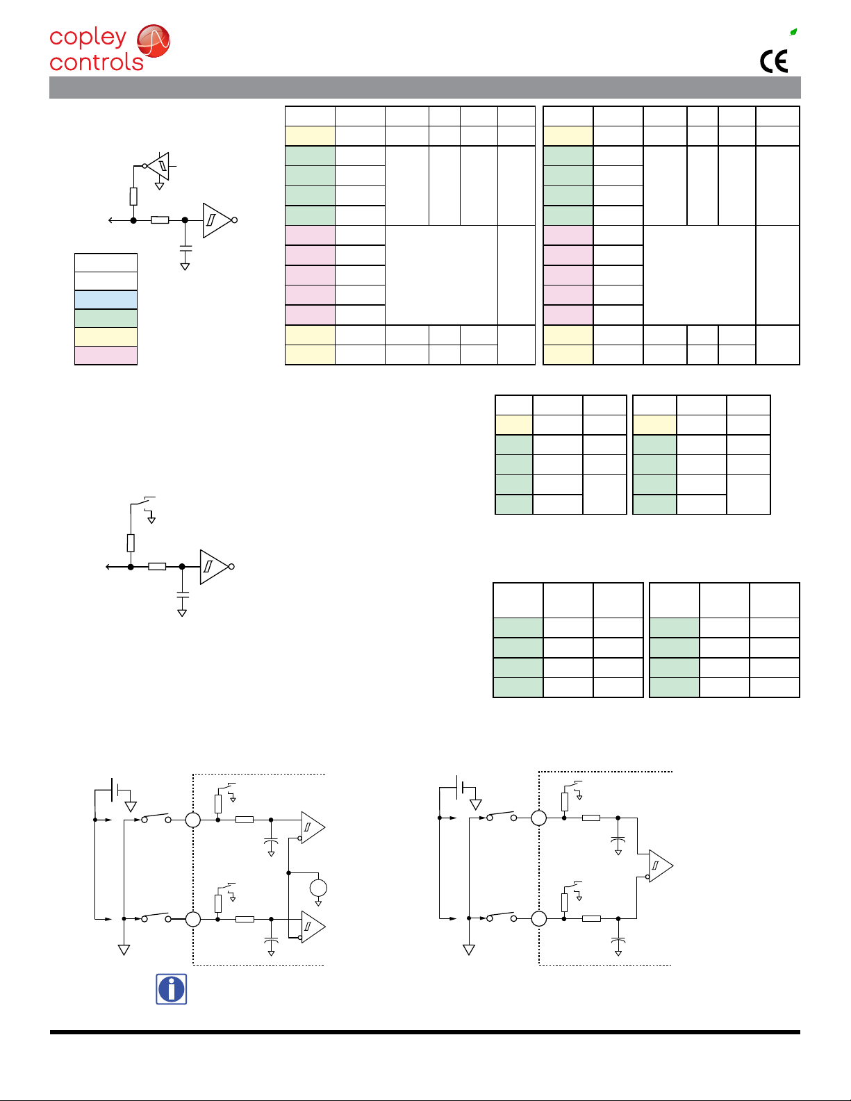
SAFE TORQUE OFF (STO)
Safety Integrity Level SIL 3, Category 3, Performance level d
Inputs 2 two-terminal: STO-IN1+,STO-IN1-, STO-IN2+, STO-IN2-
RS-232 PORT
Protocol Binary and ASCII formats
ETHERCAT PORTS
Protocol EtherCAT, CAN application layer over EtherCAT (CoE)
STATUS INDICATOR LEDS