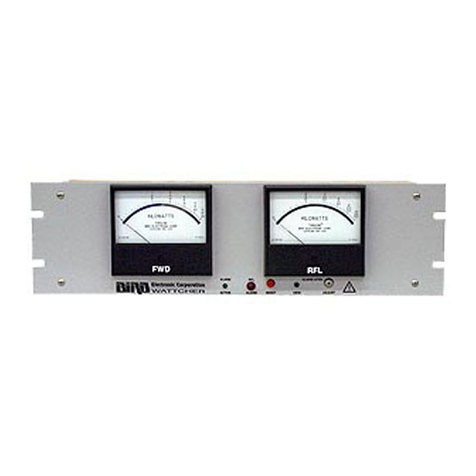
Aeroflex IFR 2398 User manual

An Aeroflex Company
Spectrum Analyzer
2398
Maintenance Manual
AC2600
Issue 1

Contains pages
for
Maintenance Manual
for
SPECTRUM ANALYZER
2398
Part
number
AC2600
Issue 1
Creation date
31
October 2002
Please open
and
fit
to the
supplied
Ring
Binder

SPECTRUM ANALYZER
2398
© IFR. 2002
No
part
of
this book may be reproduced or transmitted in anyform
or by any means, electronic or mechanical, including photocopying,
or recorded by any information storage or retrieval system, without
permission
in
writing by IFR
Printed
in
the
UK
Manual part
no.
AC2600
Issue 1
31
October 2002

Contents
Tab
numbers
PRECAUTIONS and PREFACE Before
Tab 1
Section 1 INTRODUCTION W
Section 2 THEORY OF OPERATION
[])
Section 3 ADJUSTMENT
(Il
Section 4 FAULT DIAGNOSIS
[I)
Section 5 REPLACEMENT PROCEDURES W
Section 6 PREVENTIVE MAINTENANCE
[])
Chapter 7 PARTS LIST W
Appendix
[])
IFR CONTACT NUMBERS
[I)
A brief
description
of
each
section
will
be
found
on page
9,
followed
by
a detailed
contents
list
starting
on page 11.

Safety Symbols
Where these symbols or indications appear on the instrument or in this manual,
they have the following meanings.
WARNING. Risk
of
hazard, which may cause injury
to
human body or danger
to
life.
If
a WARNING
appears on the instruments, or
in
this manual,
do
not proceed until suitable conditions are
understood and met.
CAUTION. Risk
of
hazard, which may cause fire or serious
damage
to
the instruments or other equipment.
Do not proceed until suitable conditions are
understood and met.
GROUND. Ground terminal to chassis (earth ground).
CAUTION. Contains parts and assemblies susceptible
to damage by electrostatic discharge (ESD).

1
WARNING
&1
Repair
Falling
Over
2
For Safety
IWARNING
6 I
1.
ALWAYS refer to the operation manual when
working near locations at which the alert mark shown
on the left is attached.
If
the operations are
performed
without
heeding
the advice the
operation
manual,
there
is
a risk
of
personal injury. In addition,
equipment performance may be reduced. This alert
mark
is
sometimes used with other marks and
descriptions indicating other dangers.
2.
When supplying power to this equipment, connect the
accessory 3-pin power cord to a 3-pin grounded power
outlet.
If
a grounded 3-pin outlet is not available, and
before supplying power
to
the equipment, use a conversion
adapter and ground the green wire, or connect the frame
ground on the rear panel
of
the equipment to ground.
If
power is supplied without grounding the equipment, there
is a risk
of
receiving a severe
of
fatal electric shock or
equipment damage.
3.
The user cannot repair this equipment.
DO
NOT
attempt to open the cabinet or to disassemble internal
parts. Only IFR trained service personnel or staff from
your sales representative with a working knowledge
of
electrical fire and shock hazards should service this
equipment. There are high-voltage parts in this
equipment that present a risk of severe injury or fatal
electric shock to untrained personnel.
In
addition, there
is
a risk
of
damage to precision parts.
4. This equipment should be used
in
the correct position,
If
the cabinet is turned on its side, etc., it can be unstable and
may be damaged
if
it
falls over as a result
of
receiving a
slight mechanical shock.

For Safety
Changing the Fuses
1.
Before changing the fuses,
ALWAYS
remove the
power cord from the power-outlet before replacing the
blown fuses.
ALWAYS
use new fuses
of
the type and
rating specified on the fuse marking on the rear panel
cabinet.
Cleaning
Maximum Input
T3.15A indicates a time-lag fuse.
There is risk
of
receiving a fatal electric shock if the
fuses are replaced with the power cord connected.
2.
Keep the power supply and cooling fan free
of
dust.
Clean the power inlet regularly.
If
dust accumulates
around the power pins, there is a risk
of
fire. Keep the
cooling
fan
clean
so
that the ventilation holes
are
not
obstructed.
If
the ventilation is obstructed, the cabinet
may overheat and catch fire.
3. Maximum DC voltage ratings:
RF Input ±20 Vdc
Maximum AC power ratings:
RF Input +26 dBm
Excessive power may damage the internal circuits.
3

4
Replacing Memory
Back-Up Battery
Storage
Medium
(PCMCIA)
For Safety
I CAUTION
61
4. A Primary Lithium Battery supplies the
power
for
memory back up. A battery
of
the same type should
only replace this battery; since IFR can only make
replacement, contact the nearest IFR representative
when replacement is required.
Note: The Battery life is about 7 years.
Early battery replacement
is
recommended.
5. This equipment stores data and programs using a
PCMCIA (Type
I)
SRAM Memory Card. Trace data
and Setup data may be lost due to improper use or
failure. Do not remove the IC card from equipment
being accessed. Isolate the card from static electricity.
The back-up battery in the SRAM memory card has
a limited life, replace or recharge the battery
periodically.

Product Damage
Precaution
Place-related
Warning
For Safety
I CAUTION ffi I
6.
Use
Proper
Power
Source: Do not operate this product
from a power source that applies more than the voltage
specified.
Provide
Proper
Ventilation:
To
prevent product
overheating, provide proper ventilation.
Do Not
Operate
With
Suspected Failures:
If
you suspect
there
is
damage to this product, have it inspected by
qualified service personnel.
Do Not
Attempt
To
Operate
If
Protection
May
Be
Impaired:
If
the instrument appears damaged or operates
abnormally, protection may be impaired. Do not attempt to
operate the instrument under these conditions. Refer all
questions
of
proper instrument operation to qualified service
personnel.
7.
Object
and
Liquid
Entry:
Never push objects
of
any kind
into instrument through openings as they may touch
dangerous voltage points or short out parts that could result
in
a fire or electric shock. Never spill liquid of any kind on
the instrument. Do not use this instrument near water (for
example, near a bathtub, wash bowl, kitchen sink, or laundry
tub,
in
a wet basement, or near a swimming pool). Keep the
instrument away from damp air, water and dust. Unexpected
trouble may be caused when the instrument is placed in a
damp or dusty place.
Flammable
and
Explosive Substance: Avoid using this
instrument where there are gases, and where there are
flammable and explosive substances in the immediate
vicinity.
Unstable
Location:
Do not place this instrument on an
unstable cart, stand, tripod, bracket, or table. The instrument
may fall, causing serious injury to a person, or serious
damage to the instrument. Do not place or use the
instrument
in
a place subject to vibration.
5

IFR Contact
If
this equipment develops a fault, contact the head office
of
IFR at the address in the
operation manual, or your nearest sales or service office.
6

Front Panel Power Switch
To
prevent
malfunction
caused
by
accidentally
pressing
the front
power
switch, this
equipment turns
off
the
power
if
the front
power
switch is pressed and held for more
than 1 second in the power-on state.
In
the power-on state,
if
power is removed, then reapplied, the unit will not be turned on.
Also,
if
there is a momentary
power
supply interruption
or
power failure, the unit will not
turn
on
automatically. This is because this equipment enters the standby state and prevents
incorrect data from being acquired when the line has to be disconnected and reconnected.
For example,
if
the sweep time is 1,000 seconds and data acquisition requires a long time,
momentary power supply interruption (power failure) might occur during measurement and
the line could be recovered automatically to power-on.
In
such a case, the equipment may
mistake incorrect data for correct data without recognizing the momentary power supply
interruption.
If
this equipment enters the standby state due to momentary power supply interruption or
power failure, check the state
of
the measuring system and press the front power switch to
restore power to this equipment.
Further,
if
this equipment is built a system and the system power has to be disconnected
then reconnected, the power for this equipment must also be restored
by
pressing the front
power switch.
7

DETECTION MODE
This instrument is a spectrum analyzer, which uses a digital storage system. The spectrum
analyzer makes level measurements
in
frequency steps obtained by dividing the frequency
span by the number of measurement data points (SOl). Because
of
this operation,
it
is
desired to
use the following detector modes associated associated with appropriate measurement.
Measurement Detector mode
Normal signal
POSPEAK
Random noise SAMPLE OR AVERAGE
Pulsed noise NORMAL
OCBWorACP
SAMPLE
(for analog communication systems)
OCBWorACP
POS PEAK or SAMPLE
(for digital communication system)
When a detection mode
is
specified usmg one
of
the measurement methods, make the
measurement in the specified detection mode.
8

PREFACE
SCOPE
This manual contains maintenance instructions for the IFR 2398 Spectrum Analyzer.
The information in this manual enables servicing technicians to:
• Test or replace any major assembly within the 2398 Spectrum Analyzer.
• Maintain operating conditions
of
the 2398 Spectrum Analyzer to the expected
performance standards.
• Understand principle
of
operation, relating to the overall operation
of
the 2398
Spectrum Analyzer
as
well
as
functional operation within the major assemblies.
ORGANIZATION
This Maintenance Manual
is
composed
of
the following sections:
SECTION I - INTRODUCTION
Provides a brief description
of
the electrical and mechanical configuration
of
the
2398, intended to familiarize the technician with the overall structure
of
the
instrument.
SECTION 2 - THEORY OF OPERATION
Describes how the 2398 operates on three levels
of
complexity: system level,
interactive functional level and functionally at the module (assembly) level.
SECTION 3 - ADJUSTMENT
Provides step by step procedures for calibrating the 2398.
SECTION 4 - FAULT DIAGNOSIS
Contains information for diagnosis
of
faults on the 2398.
SECTION 5 - REPLACEMENT PROCEDURES
Provides step by step procedures for removing and installing major assemblies within
the 2398.
SECTION 6 - PREVENTIVE MAINTENANCE
Contains routine instructions for cleaning and inspecting the 2398.
SECTION 7 - PARTS LIST
Provides drawings with part listings for ordering replaceable parts within the 2398.
APPENDIX
Contains useful supplementary data and test equipment information.
9

<BLANK>
10

TABLE OF CONTENTS
1.
INTRODUCTION ...............................................................................
............
1-1
General ................................................................................................................
1-
3
Electrical Description .......................................................................................... 1-3
Mechanical Description ...................................................................................... 1-3
2.THEORY OF OPERATION ........................................................................... 2-1
General ................................................................................................................ 2-3
System Theory
Of
Operation .............................................................................. 2-4
Functional Theory
Of
Operation...
..................................................................... 2-5
SpectrumAnalyzer ......................................................................................... 2-5
RF
Module
Assembly............
...................................................................... 2-6
IF
Filter
And
Amp.
Assembly...
.................................................................... 2-10
Video Detector Assembly...
.........
................................................................ 2-13
ProcessorAssembly ....................................................................................... 2-16
Motherboard
Assembly......
.......................................................................... 2-18
LCD
Inverter
Assembly.....
.......................................................................... 2-20
Key BoardAssembly ..................................................................................... 2-20
AC
Power Supply Module
Assembly.................................
...............
2-21
PCMCIAAssembly........................................................................................ 2-22
Tracking Generator Module Assembly (Option) ........................................... 2-23
3. ADJUSTMENT ............................................................................................... 3-1
INTRODUCTION ................................................................................................ 3-3
REQUIREMENTS ............................................................................................. 3-4
Test Equipment ........................................................................................... 3-4
Test Software ...................................................................................
......
...... 3-4
Main Program for
Calibration...
................................................................... 3-5
PREPARATION
............................................................................
3-7
Disassembly
...
...................................................................................
..........
3-7
Environment
.........................................................................
.... 3-7
Warm Up ..................................................................................................... 3-7
ADJUSTMENT
PROCEDURE........................
............................................ 3-8
Initialization.............................................................................
3-8
LogAmplifier Linearity Calibration ............................................................. 3-10
IF
Gain Calibration
...........
........................................................................ 3-13
RF
Attenuator Calibration ............................................................................. 3-16
SpanAttenuator Calibration ......................................................................... 3-19
Frequency Flatness Calibration ...................................................................... 3-22
Tracking Generator
Calibration.......................................................
3-25
CALIBRATION DATA
BACKUP
& SERIAL
NUMBER
SET
PROCEDURE
... 3-33
11

4. FAULT
DIAGNOSIS....
...............................................................
... 4-1
Fault diagnosis procedure for 2398
......................................................
4-4
Fault diagnosis procedure for
malfunction.............................................
4-8
Option malfunction
........................................................................
4-14
5. REPLACEMENT PROCEDURES .................................................................. 5-1
General ................................................................................................................ 5-3
Equipment Requirements ..................................................................................... 5-4
Replacement Procedures ...................................................................................... 5-5
Rear Panel ....................................................................................................... 5-6
Can CoverAssembly .......................................................................................... 5-9
Front Panel Assembly .................................................................................... 5-12
Front Frame Assembly ................................................................................... 5-15
RF Module Assembly .................................................................................... 5-18
IF FilterAnd Amp. Assembly .......................................................................... 5-21
VIDEO Detector Assembly ............................................................................. 5-24
Processor Assembly ........................................................................................... 5-24
LCD InverterAssembly .................................................................................. 5-30
Key Board Assembly ..................................................................................... 5-33
Input ProtectAssembly ................................................................................... 5-39
MSO/HSO(OPTION) Assembly ........................................................................ 5-39
LCD Module Assembly .................................................................................. 5-42
AC Power Supply Assembly ............................................................................. 5-45
DC Fan Assembly............................................................................................. 5-48
Speaker Assembly ............................................................................................. 5-51
PCMCIA Assembly(OPTION) .......................................................................... 5-54
GPIB Interface Assembly(OPTION).................................................................. 5-57
Tracking GeneratorAssembly(OPTION) ......................................................... 5-60
6. PREVENTIVE MAINTENANCE .................................................................... 6-1
External Cleaning .............................................................................................. 6-3
Internal Cleaning ...............................................................................................
6-
3
Visual Inspection ............................................................................................... 6-4
Procedure for Changing the Memory Backup
Battery..............
................
... 6-5
7. PARTS LIST ....................................................................................................... 7-1
General .............................................................................................................. 7-3
List
of
2398 Assemblies ...............................................
..........................
......... 7-4
Can CoverAssembly ......................................................................... ............. 7-4
Composite Assembly ....................................................................
..........
........ 7-7
Front Frame Assembly ................................................................................ 7-8
LCD Frame Assembly ................................................................................. 7
-11
Main Body Assembly .................................................................................. 7-12
Processor Board Assembly ........................................................................... 7-15
Rear Frame Assembly............................................................................... 7-16
Wire Harness.......................................................................................... 7-19
12

APPENDICES .......................................................................................................... A-I
A-I.
User Table
Of
I/O Connectors..................................................................... A-3
A-I-I.
Table
Of
I/O Connectors ........................................................................ A-4
A-I-2. IEEE-488 GPIB Connector ..................................................................
...
A-4
A-I-3. RS-232 Connector............................................................................. A-5
A-I-4. Printer Connector ................................................................................ A-6
A-I-5. DC Input Connector ............................................................................. A-7
13

Section 1
Introduction

SECTION 1 INTRODUCTION
SECTION 1
INTRODUCTION
TABLE OF CONTENTS
General -----------------------------------------------------------------------------------------
1-
3
Electrical Description ------------------------------------------------------------------------
1-
3
Mechanical Description ---------------------------------------------------------------------- 1-4
1-1

SECTION 1 INTRODUCTION
<BLANK>
1-2
Table of contents
Other Aeroflex Measuring Instrument manuals

Aeroflex
Aeroflex 3500A Installation and operating instructions

Aeroflex
Aeroflex ALT-8000 User manual

Aeroflex
Aeroflex 3901 User manual

Aeroflex
Aeroflex 3030 Series User manual
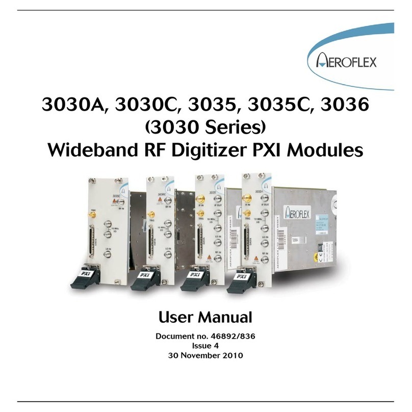
Aeroflex
Aeroflex 3030 Series User manual
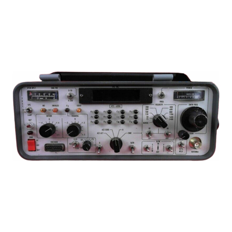
Aeroflex
Aeroflex ATC-600A-2 User manual
Aeroflex
Aeroflex 1205 User manual
Aeroflex
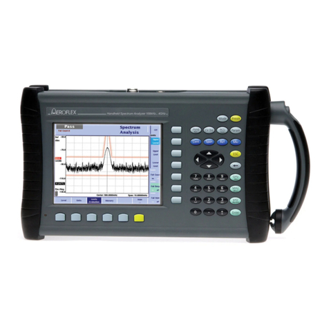
Aeroflex 9102 User manual

Aeroflex
Aeroflex 2944B User manual
Aeroflex
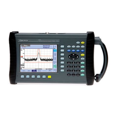
Aeroflex 9101 User manual
