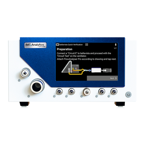
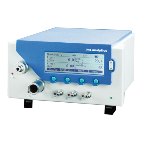
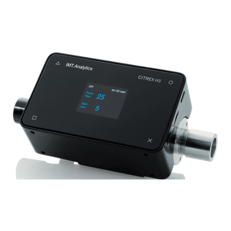
IMT Analytics FlowMeter F1 User manual

User Manual
FlowMeter F1, F2

Table of contents
1 Introduction 5
2 Intended use 6
3 Safety instructions 7
3.1 Representation of hazards, cautions and notes 7
3.2 Personnel 7
3.3 Responsibility and guarantee 7
3.4 Service life 8
4 Specifications 9
4.1 Measurement parameters 9
4.2 Principle of flow measurement 10
4.3 Special functions 10
4.4 Communication interfaces 10
4.5 Physical data 10
4.6 Calibration by user 11
4.7 Operating data 11
4.8 Gas standards for flow and volume measurement 12
4.9 Power supply 12
4.10 Battery operation 13
4.11 Directives and approvals 13
4.12 Device labels and symbols 14
4.13 Feature Set 15
5 Start-up 16
5.1 Individual parts in the packaging 16
5.2 Power supply 17
5.3 Mechanical connectors 17
5.4 Electrical interfaces 20
6 Operation 22
6.1 Switching the device on and off 22
6.2 Acoustic feedback 22
6.3 User control gestures 22
6.4 Screens 24
6.5 Menu 28
7 Measuring volume 39
7.1 General principle 39
7.2 Finding the correct trigger values 39
8 Servicing and care 40
8.1 Guidelines for servicing and care 40
8.2 Notes about changing parts 40
8.3 Preventive cleaning and servicing routines 40
8.4 Cleaning 41
8.5 Trouble shooting 41
8.6 Contact 43

Introduction
5
1
IMT Analytics AG
Validity
This documentation is valid for the product: FlowMeter F1 and F2
You will find the name FlowMeter on the type label on the back of your device.
Software and firmware version
This documentation applies to the following versions:
FlowMeter firmware – Version 1.0.000
In the case of older or newer versions there may be minor discrepancies in relation to
this User Manual.
Designations used in this User Manual
Buttons such as Power and indicators on the display such as Settings are printed
in boldface italics.
References to pages and sections
For references to pages and references, e.g. (4.5 Physical data), the symbol
(XY) is used.
Version information
Issue date of this User Manual: Release 01, 2023-02
Subject to technical modifications without notice.
1 Introduction

Intended use
6
2
2
IMT Analytics AG
This product is intended for testing and calibration purposes of medical – or other
devices or systems that generate Air / O2/ N2gas flows and / or gas pressures.
The device is intended for users who are trained in the use of measuring devices
and who can carry out tests, repairs, calibrations, maintenance and service work on
medical or other devices. No dedicated training on this specific device is required.
The device can be used in:
• Hospital service departments
• Clinics
• Medical and non-medical devices manufacturing facilities
• Workshop / testing / laboratory facilities of independent service companies
perfroming service and repair for medical and non-medical devices
FlowMeter is intended for use in an indoor test laboratory environment. It may only be
used outside the nursing sector. It must not be used directly on patients or devices
that are connected to patients. The FlowMeter is intended for over-the-counter sale.
FlowMeter is the solution for measurements in the following areas:
• Flow (±300L/min)
• Volume (0 L–500 000L)
• Differential pressure (±250mbar)
• Absolute pressure in the Flow channel (0.5–2bar)
• Temperature in the Flow channel (-10–50°C)
• Humidity in the Flow channel (0–100%RH, non-condensing)
FlowMeter is a measuring instrument for testing and calibrating pur-
pose on medical and non-medical devices or systems. It must not be
used for patient monitoring. FlowMeter must not be used directly on
patients or devices that are connected to patients.
This product is intended to be used at elevations of up to 5000m operation altitude
in buildings.
2 Intended use

7
Safety instructions
3
IMT Analytics AG
This User Manual uses the representation below to specifically draw attention to
residual risks during intended use and emphasize important technical requirements.
Information and/or instructions and prohibitions to prevent damage of
any kind.
Work on and with FlowMeter may only be performed by persons who
have undergone appropriate general technical training and have the
necessary experience.
Themanufacturer accepts no responsibilityor guarantee and willbe exempt fromli-
ability claims accordinglyif theoperatoror any third parties:
• fail to use the device in accordance with its intended use
• disregard the specifications
• tamper with the device in any way (conversions, modifications, etc.)
• operate the device with accessories that are not listed in theassociatedsets
of product documentation
• Report any serious incident that has occurred in relation to the
medical device to the manufacturer (8.6.2 Technical support)
and the authority having jurisdiction in their locale
• The device has user replaceable parts (8.3 Preventive cleaning
and servicing routines)
• Neligence of warning and error messages can lead to damage of
the device
• The device including the measurement channel shall not be ex-
posed to high level of volatile organic compounds (VOC). Doing
so may lead to permanent offset of the humidity sensor.
• Only use original packaging in good condition for transport or
storage
• The device must not be placed in a pressure chamber
• The device is not intended to measure flammable or combustible
gases
• The device is not intended to measure liquids
• The device must not be connected to a telecom network
• The device must only be connect to approved equipment with
CE, CSA, UL or other equivalent safety mark to ensure double
insulation
3.1 Representation of hazards,
cautions and notes
3 Safety instructions
3.2 Personnel
3.3 Responsibility and guarantee

8
Safety instructions
3
IMT Analytics AG
Although the devicemeets high quality and safety standards andhas
beenconstructed and tested according to the current state of the
art,it is not possible to rule outthe risk of injuries withseriousconse-
quencesif the device is not used in compliance with the intended use
(improperly) or is misused. Therefore, please read this User Manual
carefully and keep this documentation in a readily accessible place
close to your device.
The typical service life of the device is specified as 10 (ten) years, provided it
is handled properly in accordance with this User Manual.
3.4 Service life

Specifications
9
4
IMT Analytics AG
Parameter Value
Flow1
(4.13 Feature Set)
Range
Accuracy
±300L/min
FlowMeter F1:
±1.9% or ±0.05L/min
FlowMeter F2:
±1.7% or ±0.05L/min
Volume Range
Accuracy
0L–500 000L
±4% or ±0.01mL
Differential pressure2Range
Accuracy
±250mbar
±0.5% or ±0.15mbar
Absolute pressure in the
Flow channel
Range
Accuracy
0.5–2bar
±10mbar
Temperature3Range
Accuracy
-10–50°C
±1°C
Humidity2Range
Accuracy
0–100%RH*
<20%RH: ±5%RH*
20%–80%RH: ±3%RH*
>80%RH: ±5%RH*
Accuracy valid
• between 10 °C and 30 °C (channel temperature)
• between 950 hPa and 1250 hPa
• zero offset calibration performed after warm-up
• for measurements performed within 4 h after last zero offset calibration at
same ambient conditions
1
Flow accuracy specified is valid under the above mentioned general conditions and for an air flow in
positive flow direction.
• Add 0.05 % of reading per 1°C outside the range of 10 °C to 30 °C (channel temperature)
• Add 0.005 % of reading per 10 hPa above 1250 hPa
• Add 0.01 % of reading per 10 hPa below 950 hPa
• Add 0.05 % of reading per 10 % oxygen concentration above 21 %
• Add 0.2 % of reading for negative flow direction
Flow accuracy stated with gas (channel) temperature and ambient temperature within 10 °C of each
other. Add 0.05 % of reading per 1 °C above 10 °C temperature difference.
2Only available for the model FlowMeter F2
3At flow rate ≥ 50 L/min, screen brightness ≤ 30 %, battery not charging
* Non-condensing
All flow and volume specifications are based on STP gas standard at
21.1 °C and 1013.25 mbar.
For all specifications with absolute and relative tolerances, the greater
value applies (for example: ±1.9% of reading or ±0.05L/min abso-
lute, whichever is greater).
4 Specifications
4.1 Measurement parameters

Specifications
10
4
IMT Analytics AG
Flow in the flow channel is determined by differential pressure measurement. To build
up differencial pressure Δp, a measuring disc is used to provide flow resistance. For
flow rates >50 L/min the differential pressure Δp2 is used. For lower flows, the Flow-
Meter uses Δp1 to improve the accuracy at lower flow rates.
ƞ: dynamic viscosity of the gas [Pa s]
ρ: gas density [kg/m3]
c1, c2: device-specific constants (channel geometry)
Dynamic viscosity
The viscosity of a medium is its resistance to the flow and shear of the current. Vis-
cosity is extremely dependent on temperature. The viscosity of a medium is slightly
dependent on the pressure and moisture content of the medium.
Density
Density is the unit for the mass per unit volume of the medium. Density is very de-
pendent on pressure and temperature.
The impact of ambient conditions is hence the reason why flow is occasionally con-
verted to standard conditions.
(4.8 Gas standards for flow and volume measurement)
Automatic battery operation in the event of a power failure.
• USB-A: for data recording and software updates
• USB-C: no communication, used only for charging
• RJ-10 (serial port) to stream measurement values and set up the device
Weight: 350g
Size (l × w × h): 200×80×60 mm
Gas types: Air, O2, N2and mixtures: Air/O2
4.2 Principle of flow
measurement
4.3 Special functions
4.4 Communication interfaces
4.5 Physical data

Specifications
11
4
IMT Analytics AG
Offset calibration of the pressure and flow sensors (6.5.7 Zero offset calibration).
Degree of protection, against water and dust, according to IEC 60529: IP 20
The two devices FlowMeter F1 and FlowMeter F2 have 3 different modes:
• Battery operated
• Mains supplied / battery charging
• Switched off / storage
Please note the different ambient condition for the different modes. The allowed con-
ditions for the Flow channel and the device enclosure are different.
Battery operated
Environment conditions Allowed range
Temperature (flow channel/enclosure) -10–50°C (14–122°F)
Air humidity (enclosure) 10%–90%RH*
Air humidity (flow channel) 0%–100%RH*
Absolute pressure in flow channel 50kPa–200kPa
Atmospheric pressure 54kPa–120kPa
Mains operated
Environment conditions Allowed range
Temperature (flow channel/enclosure) 5–40°C (41–104°F)
Air humidity (enclosure) 10%–90%RH*
Air humidity (flow channel) 0%–100%RH*
Absolute pressure in flow channel 50kPa–200kPa
Atmospheric pressure 54kPa–120kPa
4.6 Calibration by user
4.7 Operating data

Specifications
12
4
IMT Analytics AG
Switched off / storage
Environment conditions Allowed range
Temperature (flow channel/enclosure) -10–60°C (14–140°F)
Air humidity (flow channel/enclosure) 5 – 95 % RH*
Absolute pressure in flow channel 50kPa–200kPa
Atmospheric pressure 54kPa–110kPa
* Non-condensing
FlowMeter converts the flow and volume readings measured in the device to match
the conditions of the standard selected. The following gas standards are supported
by FlowMeter:
Gas standard Temperature Pressure Relative
humidity
Ambient Temperature and
Pressure
ATP Current gas
temperature
Current
ambient pressure
Current
gas humidity
Channel Temperature and
Pressure
CTP Current gas
temperature
Current
channel pressure
Current
gas humidity
Standard Conditions USA STP 21.1°C (70°F) 1013.25mbar
(760mmHg)
0%
Body Temperature and
(Ambient) Pressure Sat-
urated according to ISO
80601-2-12:2011
BTPS-A 37°C (99°F) Current
ambient pressure
100%
Please refer to 11 Measurement parameters and units. Here, you
will also find the conversion factors for the units of measurement.
Input voltage of the power supply: 100–240VAC (±10%), 50–60Hz, 0.6A
Output voltage of the power supply: 5VDC, 3.0A
FlowMeter input voltage: 5VDC, 2.5A
The original power supply from IMT Analytics must be used for trouble-free and relia-
ble operation. It is power tested and approved according to IEC 62368-1.
4.8 Gas standards for flow and
volume measurement
4.9 Power supply

Specifications
13
4
IMT Analytics AG
Operating time during battery operation: at least 4 hours.
Charging the battery
A complete charging process takes about 4 hours in normal conditions. The service
life of the battery is extended if the battery is not completely discharged. Do not store
the device with a discharged battery. Optimal state of charge for long term storage
is 80%.
The battery is not user replaceable and must not be replaced with a
different type. Doing so may lead to an explosion, burn or fire hazard.
The device indicates visually and audibly when the battery must be
charged. Please do not store the device if the battery is in a depleted
state.
Caution:Complete depletion can damage the battery beyond
repair!
• IEC 61010-1
• IEC 61326-1
• CAN/CSA-C22.2 No. 61010-1-12
• UL 61010-1 3rd Edition
The device is classified as Pollution Degree 2.
The device is classified as Overvoltage Category II.
For the USB connection
V1.1 is used (12Mbit)
For RJ-10 connection
If the device is to be actuated via the RS-232 interface, your dealer will be pleased to
provide you with a detailed protocol.
The device is not intended for use outside a building.
Simplified EU Declaration of Conformity
Hereby, IMT Analytics AG declares that the radio equipment types FlowMeter F1 and
FlowMeter F2 are in compliance with Directive 2014/53/EU.
The full text of the EU declaration of conformity is available at the following internet
address: www.imtanalytics.com
4.10 Battery operation
4.11 Directives and approvals

Specifications
14
4
IMT Analytics AG
The following labels and symbols can be found on FlowMeter, packaging or
accessories:
Symbol Description
Warning notice
Power button
Alternating current
Class II equipment
For indoor use only
Direct current
Power input
USB Port to connect an USB flash drive
Serial interface
Conforms to CE Directives and Regulations
Safety Mark for North America for FlowMeter
Mark for proof of product compliance to North American safety stand-
ards
Manufacturer
Date of Manufacture
The operating instructions should be considered when
operating the device
Serial Number
Waste Electrical and Electronic Equipment
Conformity with Low Voltage Directive 2014/35/EU
Mark for United Kingdom Conformity Assessment
This equipment contains specified radio equipment that has been
certified to the Technical Regulation Conformity Certification under the
Radio Law
UDI Data
Matrix Code
Unique Device Identification
(01) GTIN-No.
(11) Production Date
(21) Serial No.
4.12 Device labels and symbols

Specifications
15
4
IMT Analytics AG
Symbol Description
Catalog number
Keep dry
Protect from sunlight
Temperature for transport and storage
Humidity range for transport and storage
Atmospheric pressure for transport and storage
The two devices FlowMeter F1 and FlowMeter F2 differ from each other in terms of
the available features.
The models can be easily distinguished by the color of the top cover.
FlowMeter F1 FlowMeter F2
Top cover Black Blue
Flow measurement ±300L/min
±1.9% or ±0.05L/min
±300L/min
±1.7% or ±0.05L/min
Volume measurement available available
Absolute pressure in flow channel available available
Differential pressure ports not available available
Temperature measurement available available
Humidity measurement not available available
Bluetooth available in subsequent
software release
available in subsequent
software release
Statistic screen not available available
4.13 Feature Set

Start-up
16
5
IMT Analytics AG
Picture Description
FlowMeter
Power supply
Protection Filter RT019
Calibration certificate
5.1 Individual parts in the
packaging
5 Start-up

Start-up
17
5
IMT Analytics AG
The power supply socket is located at the rear of FlowMeter.
The device can be disconnected from the mains by disconnecting the
power supply. The power supply should therefore be easily accessible.
5.2.1 Supply voltage
The mains voltage of the power supply is 100–240VAC at 50–60Hz.
Before switching on, make sure the operating voltage of the power
supply is compatible with the local mains voltage. You will find this
information on the rating plate on the back of the power supply.
5.3.1 Protection Filter RT019
To protect the device against contaminants and particles in the flow channel, the
Protection Filter RT019, must be used for flow measurements. Connect the
Protection Filter RT019 to the flow channel inlet port before connecting the device
under test.
Particles of dirt in the air can clog the measuring system and thus
lead to incorrect measurements. The Protection Filter RT019 must be
checked regularly (8.3 Preventive cleaning and servicing routines).
5.2 Power supply
5.3 Mechanical connectors

Start-up
18
5
IMT Analytics AG
5.3.2 Flow channel
The flow channel can be used to perform gas flow measurements from -300L/min
to 300L/min. The channel includes pressure, temperature and humidity1sensors.
Flow channelFlow channel
Measuring range: ±300L/min
Accuracy: FlowMeter F1: ±1.9% or ±0.05L/min
FlowMeter F2: ±1.7% or ± 0.05L/min
When working with relatively high humidity, ensure that condensation
does not form in the unit! Water can irreparably damage the sensors!
The device including the measurement channel shall not be exposed
to high level of volatile organic compounds (VOC). Doing so may lead
to permanent offset of the humidity sensor.
1Only available for the model FlowMeter F2

Start-up
19
5
IMT Analytics AG
5.3.3 Differential pressure1
The differential pressure connectors can be used for differential pressure measure-
ments.
Differential pressure ports
+ −
Measuring range: ±250mbar
Accuracy: ±0.5% or ±0.15mbar
1Only available for the model FlowMeter F2

Start-up
20
5
IMT Analytics AG
5.4.1 USB connection for charging
The USB-C port is used to connect the power supply. The port is located at the rear
of the device.
Rating: 5V, 2.5A
The device must only be connect to approved equipment with CE, CSA, UL or other
equivalent safety mark to ensure double insulation.
5.4.2 RS-232
The RS-232 interface is used for remote monitoring or control.
4 3 2 1
Actuation of the RS-232 port takes place via a special RS-232 cable. If the device
shall be actuated via the RS-232 interface, your dealer will be pleased to provide you
with a detailed protocol.
FlowMeter pin assignment (RJ-10 connector):
Pin 1 NC
Pin 2 RxD (Input of FlowMeter)
Pin 3 TxD (Output of FlowMeter)
Pin 4 GND
5.4 Electrical interfaces
This manual suits for next models
1
Table of contents
Other IMT Analytics Measuring Instrument manuals
Popular Measuring Instrument manuals by other brands

ATI Technologies
ATI Technologies Scorpion X2 installation instructions
Milwaukee
Milwaukee REDLITHIUM Operator's manual

Tektronix
Tektronix FiberMaster TFP2A Service manual
Primes
Primes PocketMonitor operating manual

KPS
KPS KPS-PA20 MINI instruction manual
Auber Instruments
Auber Instruments SYL-1813 instruction manual


