AeroLEDs Sunspot 36-4314 User manual
0019-0015 Installation Instructions SunSpot 36-4313_4314 Rev IR Page 1 of 9
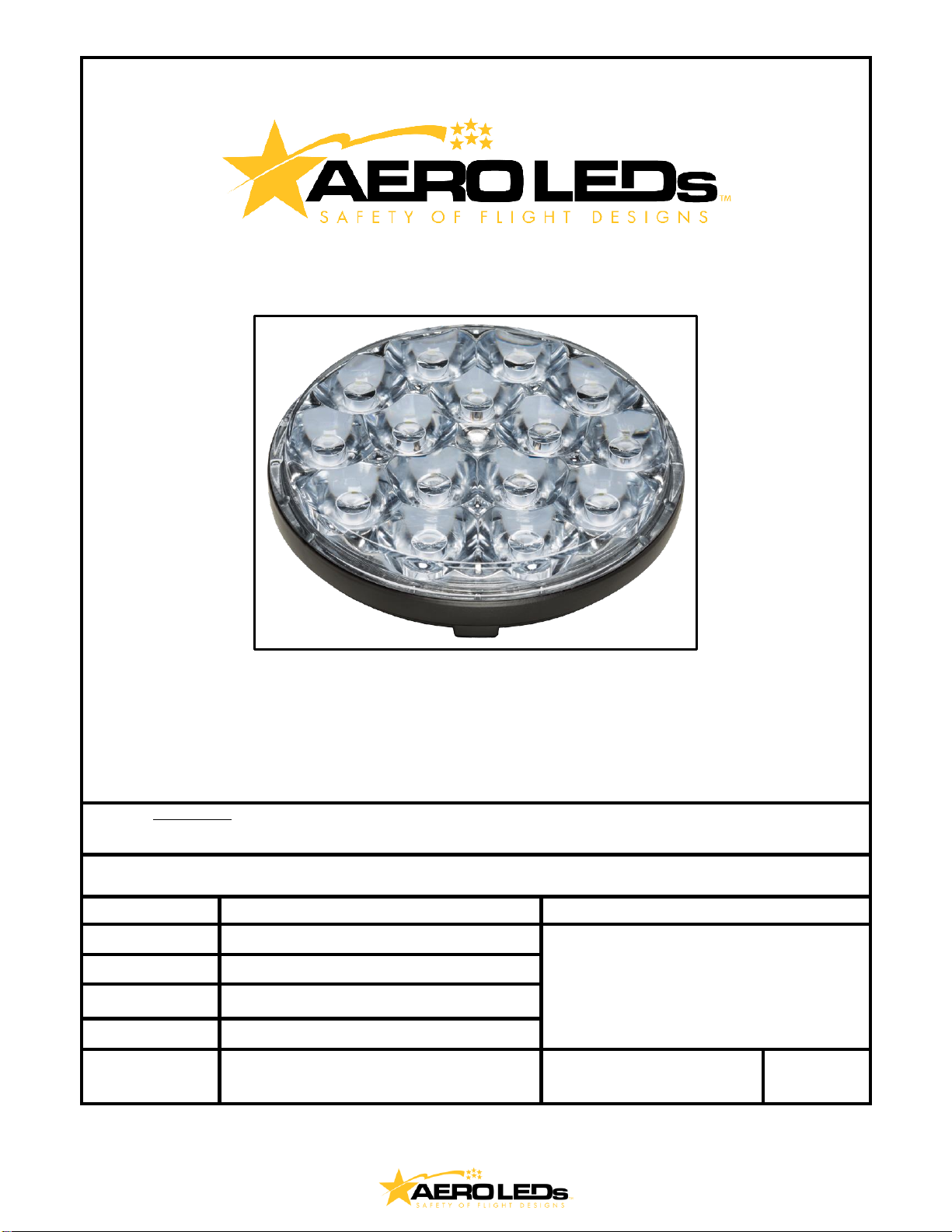
Installation Instructions
Sunspot 36-4313/4314
AeroLEDs, LLC
8475 W. Elisa St.
Boise, ID, 83709
208-850-3294
NOTE:
A printed copy of this document may not be the latest revision.
It is the responsibility of the user to ensure that
the latest revision is used.
The latest revision of this document may be printed from the AeroLEDs electronic document
repository. Revision history follows on page 2
This document contains proprietary information of AeroLEDs. Neither receipt nor possession thereof confer any right to
reproduce or use, or disclose, in whole or in part, any such information without written permission from AeroLEDs.
Approval
Name
Intent
Author
Robert Prew
Installation and Operation Instructions for
the Sunspot 36-4313/4314 series lights (01-
1030-4313/4314)
Check
Nate Calvin
Quality
Mike D’Amico
Date:
16 October 2018
Status:
Released
Typed signatures indicate approval. Handwritten,
or electronic signature approval of this document
is on file at AeroLEDs, Boise, Idaho.
Document Number
0019-0015
Revision
IR
0019-0015 Installation Instructions SunSpot 36-4313_4314 Rev IR Page 2 of 9
REVISION RECORD
Rev
Description
Date
Author
IR
Initial Revision
10/16/2018
Robert P.
TABLE OF CONTENTS
Limitations and Installations........................................................................................................................................3
Equipment Limitations:...............................................................................................................................................3
Airworthiness Limitations: ..........................................................................................................................................4
Instructions for Continued Airworthiness ...................................................................................................................4
Installation Procedures...............................................................................................................................................4
Wire Sizes..................................................................................................................................................................5
Removal.....................................................................................................................................................................5
Installation..................................................................................................................................................................5
Troubleshooting .........................................................................................................................................................5
Wiring Diagrams............................................................................................................................................................6
Wiring Diagram for Single Sunspot with Pulse ..........................................................................................................6
Wiring Diagram for Single Sunspot Without Pulse ....................................................................................................6
Wiring Diagram for Dual SunSpots with Wig-Wag.....................................................................................................7
Wiring Diagram for Four LED SunSpots with Wig-Wag.............................................................................................8

0019-0015 Installation Instructions SunSpot 36-4313_4314 Rev IR Page 3 of 9
www.aeroleds.com Installation Guide:
P/N 01-1030-4313 or P/N 01-1030-4314
LED Landing or Taxi light
Sunspot 36 4313-H and 4314-H
P/N 01-1030-4313-H or P/N 01-1030-4314-H
LED Landing or Taxi light with
mailto:sales@aeroleds.com built-in pulse recognition mode
Operational Voltage:
14 Volt DC
Input Current:
6.5 Amps Peak
Limitations and Installations
Equipment Limitations:
Mount in approved PAR36 bulb holder with circuit breaker or fuse appropriate for rated current. For
retrofit installation existing circuit breaker or fuse can typically be used. The procedures contained
herein are not intended to conflict with the procedures set forth by aircraft and engine manufacturers,
nor do they supersede the FAA approved manuals and FAA regulations. Consult 14CFR, §43.13-1B for
guidance on acceptable methods, techniques, and practices.
0019-0015 Installation Instructions SunSpot 36-4313_4314 Rev IR Page 4 of 9
Airworthiness Limitations:
The Airworthiness Limitations section is FAA approved and specifies maintenance required under 14
CFR, §43.16 and 14 CFR, §91.403 of the Federal Aviation Regulations unless an alternative program
has been FAA approved. There are no new (or additional) airworthiness limitations associated with this
equipment and/or installation.
Instructions for Continued Airworthiness
The Sunspot 36 LED landing or taxi light assembly is designed with 15 high power LEDs mounted
behind a lens. The lights contain no user repairable items; should more than two LEDs fail; the unit
must be replaced.
Interval
Description
Notes
50 hr.
•Perform functional check on landing
light(s)
•Replace components as required
Landing and taxi lights are not field
repairable and should be sent to
manufacturer for repair/replacement
if defective
100 hr.
•Perform functional check on landing
light(s) / replace unit if defective
•Inspect for discoloration of lens
•Inspect mounting for security
•Inspect all connectors for good
engagement
•Inspect wiring for chaffing / defects
•Replace components as required
Landing and taxi lights are not field
repairable and should be sent to
manufacturer for repair/replacement
if defective
Annually
--SAME AS 100 HOUR--
Landing and taxi lights are not field
repairable and should be sent to
manufacturer for repair/replacement
if defective
Installation Procedures
The installation procedure described in the following text is for a single light installation, and multiple
light installations. The pulsing function of the -H model landing and/or taxi light(s) is a self-contained
feature and does not require the use of an externally mounted pulse light controller. Wiring diagrams
are provided for single, dual, and quad light installations for the -H model to illustrate typical wiring for
enabling the pulsing mode and wig-wag synchronization. For the non-pulsing model lights, existing wire
and switches and breakers will be utilized. For the -H model lights, an additional wire and switch will be
required to enable the pulse mode, and for multiple lights an additional synchronization wire will be
required.
Refer to the aircraft manufacturer’s service manual and/or illustrated parts catalog: Locate the landing
and/or taxi light system installed in your aircraft. This will provide details on the location of the
components and the assembly details.
WARNING: If the aircraft being modified incorporates a remote sensor (flux gate) compass: DO NOT
mount the LED light within 24 inches of the remote compass components. After installation of the LED
lighting system, a compass swing MUST be performed with the landing/taxi lights ON & OFF and the
position error card must be annotated accordingly.
WARNING: DO NOT mount the LED light with less than 4 inches clearance to exhaust system
components unless an adequate heat shield is utilized to block radiant heat.
0019-0015 Installation Instructions SunSpot 36-4313_4314 Rev IR Page 5 of 9
Wire Sizes
Reference: AC43.13-1B, Chapter 11, §4 and §5 for appropriate wire sizing and fuse/breaker protection
Removal
Prepare the aircraft for maintenance: Make sure all switches are in the OFF/NORMAL position, attach
maintenance warning tags, pull landing/taxi light circuit breakers.
Reference airframe manufacturer’s current maintenance manual to remove any light covers to gain
access to lamp assembly(s) and bracket(s).
Disconnect connection to positive aircraft power.
Disconnect ground from aircraft power.
Remove existing lamp(s) from brackets, mark and retain hardware.
Record weight of removed lamps.
Installation
Reference airframe manufacturer’s current maintenance manual and install LED light(s) in brackets
using retained hardware.
Install suitable aircraft approved connecters to wires coming from landing light assemblies and wires
routed from switch using appropriate wiring diagram to the number of lights shown on pages 7-9. Note
that the non pulsing version only has screw terminals for #6 ring terminals and does not support the
pulse function. The screw terminals are not polarized, so the power and ground can be connected to
them in either order. The positive wire for powering the pulse mode is connected to the yellow wire.
Follow the wiring diagrams for connecting the blue and green synchronization wires for two and four
light installations.
If necessary, install an appropriate aircraft approved switch and circuit breaker of correct rating for the
lights installed for the pulse function. Original landing light switch/switches may be used.
Placard switches appropriately.
Power up aircraft and verify proper operation of LED light(s), in both pulsing and steady functions (as
appropriate to the installation)
Using the appropriate aircraft maintenance manual, verify that the light angle has not changed, and is
oriented & aimed in accordance with manufacturer’s instructions.
Perform EMI test to verify there is no interference caused by light installation.
Reinstall any light covers removed to gain access to lamp assemblies and brackets.
Enter appropriate logbook entry detailing work, and if necessary fill out and submit appropriate form
337 for work accomplished.
Perform an operational check of the landing/taxi light(s) in accordance with 14CFR, §91.407 (b) (c) to
determine that the installed landing/taxi light(s) provide enough light for night operations in accordance
with 14CFR, §23.1383.
Weight & balance change from standard position light assemblies to LED landing light assemblies is
considered negligible.
Troubleshooting
Check for bus voltage at power input wire to the light, reestablish power if inadequate power is found.
Check for excessive resistance at light ground and repair if necessary. Remove and bench check light if
wiring is verified good.
This manual suits for next models
3
Table of contents


