Aeroneb Solo System User manual
Rx Only
US
8
30(mins.)
Symbols for Page 8 and 9
Instruction Manual


Part Number: AG-AS3050-EN
Rev. J
© 2011 Aerogen Ltd.
Instruction Manual
Aeroneb®Solo System

This page has been intentionally left blank

Aeroneb®Solo System Instruction Manual v
Table of contents
Introduction 1
System description 2
Warnings 5
Electromagnetic susceptibility 7
Symbols 9
Controls and indicators 11
Warranty 13
Life of Product 13
Assembly and Installation 14
Recharging the Battery 21
Installation for use with a ventilator 21
Installation for use with a mask........................................25
Installation for use with a mouthpiece..............................26
Adding medication 27
Nebulization 28
Functional test 30
Cleaning of Pro-X Control Module 32
Troubleshooting 33
Order numbers 36
Specications 38
Physical 38
Environmental 38
Performance 39
Power 39
Appendix 1 EMC tables 41

vi Aeroneb®Solo System Instruction Manual
List of Figures
Figure 1: Aeroneb®Solo System 2
Figure 2: Aeroneb®Pro-X controls and indicators 11
Figure 3: Connecting nebulizer unit to T-piece 14
Figure 4: Connecting control module and nebulizer unit 15
Figure 5: Connecting the Aeroneb®Pro-X AC/DC adapter 15
Figure 6: Connecting tubing and syringe to
the Aeroneb®Solo for continuous nebulization 18
Figure 7: Connecting to an adult breathing circuit 22
Figure 8: Connecting to a pediatric breathing circuit 22
Figure 9: Connecting to a neonate breathing circuit 22
Figure 10: Alternative neonatal breathing circuit using
neonate T-piece 23
Figure 11: Control module and universal mounting bracket
(Vertical) 24
Figure 12: Control module and universal mounting bracket
(Horizontal) 24
Figure 13: Equipment mount adapter 24
Figure 14: Connecting to a mask...........................................25
Figure 15: Connecting to a mouthpiece.................................26
Figure 16: Filling the nebulizer unit with a pre-lled ampoule 27
Figure 17: Starting and stopping nebulization 29
List of Tables
Table 1: Aeroneb®Solo system symbols 9
Table 2: Aeroneb®Pro-X controls and indicators 12
Table 3: Aeroneb®Pro-X troubleshooting 33
Table 4: Aeroneb®Solo Parts List 36

Aeroneb®Solo System Instruction Manual 1
Introduction
The Aeroneb®Solo System is an iteration of the Aeroneb®
Professional Nebulizer System. The indications for use
of the Aeroneb®Professional Nebulizer System are given
below. The Aeroneb®Solo System, which consists of the
Aeroneb®Solo nebulizer and the Aeroneb®Pro-X controller,
is a nebulizer system designed for use with mechanically
ventilated patients to aerosolize physician-prescribed
medications for inhalation which are approved for use with a
general purpose nebulizer. The Aeroneb®Solo nebulizer is for
single patient use only and the Aeroneb®Pro-X controller is
for re-use.
The Aeroneb®Solo System is suitable for use with neonate,
pediatric and adult patients as described in this manual. It is
for intermittent and continuous nebulization that incorporates
Aerogen’s OnQ™ Aerosol Generator.
The Aeroneb®Solo nebulizer is designed to operate in-line
with standard ventilator circuits and mechanical ventilators.
It operates without changing patient ventilator parameters and
can be relled without interrupting ventilation.
The Aeroneb®Pro-X control module operates from the AC/DC
adapter and can be operated on its internal rechargeable
battery for up to 45 minutes when fully charged. The product
operates without compressed gas, making it suitable for
portable applications.
Indications for Use:
The Aeroneb®Professional Nebulizer System is a portable
medical device for multiple patient use that is intended to
aerosolize physician-prescribed solutions for inhalation
to patients on and off ventilation or other positive pressure
breathing assistance. The Aeroneb®Professional Nebulizer
System is suitable for use in adult, pediatric and neonate
patients as described in the Instruction Manual.
2 Aeroneb®Solo System Instruction Manual
System description
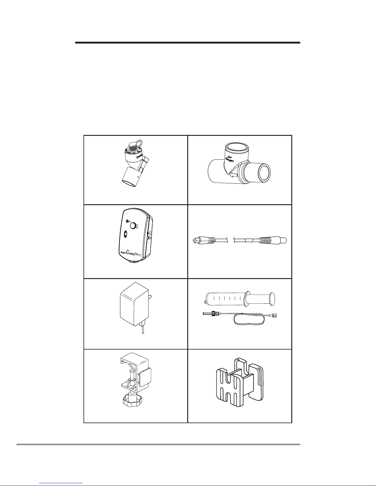
The Aeroneb®Solo System (Figure 1) includes the following
components: nebulizer unit (aerosol generator and plug),
T-piece (adult)*, Aeroneb®Pro-X control module, control cable,
AC/DC adapter and mounting brackets. (Pedatric & neonate
adapters and continuous nebulization tube set are sold
separately).
1. Nebulizer unit with plug 2. T-piece (Adult)*
30Min.
ContinuousMode
On/Off
!
Ti mer
3. Control module 4. Control Module Cable
5. AC/DC adapter
60
50
10
20
30
40
ml
6. Continuous Nebulization
Tube Set
7. Universal mounting bracket 8. Equipment mount adapter
Figure 1: Aeroneb®Solo System

Aeroneb®Solo System Instruction Manual 3
1. The nebulizer unit holds up to 6mL of liquid
medication. The nebulizer unit is clear to allow visual
monitoring of medication levels and aerosolization.
When the nebulizer unit is connected into the
ventilator circuit, the silicone plug can be opened
and closed in between doses without causing loss of
circuit pressure.
Within the nebulizer unit is an OnQ™ Aerosol
Generator, which consists of a domed aperture plate
with precision-formed holes that control the size of the
aerosol droplets and a vibrational element that creates
micro-pumping action to aerosolize medication.
Gravity brings the medication in contact with the
aerosol generator; the liquid is then drawn through
the aperture plate and converted into an aerosol.
2. The T-piece securely connects the nebulizer unit
into the breathing circuit. The T-piece connections
are standard male and female 22mm conical ports
and connect to standard patient breathing circuits.
Aerogen recommends that the Aeroneb®Solo
nebulizer be used in conjunction with a relevant
disposable T-piece supplied by Aerogen.
3,4,5. The control module can operate from the AC/DC
adapter or the internal rechargeable battery. The
control module includes an on/off power button
and sockets for the control module cable and the
AC/DC adapter. The control module also includes
indicators for nebulization cycle selection (30 minutes
or continuous), battery charge status and fault
conditions.
6. The Aeroneb®Solo can be operated continuously
by attaching the continuous nebulization tube set
accessory. The continuous nebulization tube set is
designed for use with a syringe pump for continuous
drug dosing.

4 Aeroneb®Solo System Instruction Manual
7. A universal mounting bracket clamps the control
module to standard IV poles and medical rail systems.
8. An equipment mount adapter mounts the control
module on standard equipment mounts.

Aeroneb®Solo System Instruction Manual 5
Read and study all instructions before using the
Aeroneb®Solo system. Only medical personnel should
operate the device.
Perform functional test prior to use to ensure correct operation
(see page 30).
This is a single patient use device not to be used on more
than one patient to prevent cross infection.
Do not use beyond dened life (see page 13).
During use observe for correct functioning of the nebulizer.
The nebulizer unit and T-piece, as packaged, are not sterile.
Do not autoclave the Aeroneb®Solo nebulizer.
The continuous mode can only be operated from the mains
supply and cannot be operated by battery power.
To ensure correct and safe connection between the nebulizer
and the medication reservoir, trace the medication tube from
the nebulizer back to the medication reservoir to make sure
the medication tube is connected to the correct source.
Do not use a lter or heat-moisture exchanger (HME) between
the nebulizer and patient airway.
Do not wrap the nebulizer cable tightly around any of the
system components.
Do not place the control module in an incubator during use.
To avoid exhaled medication affecting the ventilator, follow
ventilator manufacturer’s recommendations for use of a
bacterial lter in the expiratory limb of a breathing circuit.
Only use physician-prescribed solutions that are approved for
use with a general purpose nebulizer.
To ensure optimum drug administration, consult the
drug manufacturer’s instructions regarding suitability for
nebulization.
Warnings

6 Aeroneb®Solo System Instruction Manual
Do not use in the presence of a ammable anesthetic mixture
combined with air or with oxygen or nitrous oxide.
Do not use the Aeroneb Solo in conjunction with the
administration of volatile anaesthetics as this may have an
adverse effect on the Aeroneb Solo nebuliser or T-piece plastics.
Do not use to aerosolize alcohol-based medications, which
can ignite in oxygen-enriched air under high pressure.
To avoid the risk of re, do not use in the presence of
ammable substances.
To avoid damage to the nebulizer:
• Donotapplyunduepressuretothedomedaperture
plate in the center of the nebulizer.
• DonotpushouttheOnQ™AerosolGenerator.
• Donotuseasyringewithaneedletoaddmedication.
• Donotuseabrasiveorsharptoolstocleanthe
nebulizer unit.
Do not use the Aeroneb®Solo nebulizer with the reusable
connectors available with the Aeroneb®Pro nebulizer.
Aerogen recommend use of the relevant disposable T-pieces
and adapters provided by Aerogen with the Aeroneb®Solo
nebulizer.
Inspect all parts before use, and do not use if any parts are
missing, cracked or damaged. In case of missing parts,
malfunction or damage, contact your Aerogen product sales
representative.
Do not immerse or autoclave the control module or AC/DC
adapter.
Use only with components specied by Aerogen.
Do not use or store outside of specied environmental
conditions.
To avoid mechanical or electrical damage, do not drop the
nebulizer unit or the control module.
Warnings

Aeroneb®Solo System Instruction Manual 7
Do not use in the presence of devices generating high
electromagnetic elds such as magnetic resonance imaging
(MRI) equipment.
The Aeroneb®Pro-X control module contains a nickel metal
hydride (NiMH) rechargeable battery, which should be
disposed of in accordance with local governing restrictions at
the end of its useful life.
Follow local laws and recycling plans regarding disposal or
recycling of components, batteries and packaging.
The Aeroneb®Solo nebulizer is designed for use in continuous
mode only when used with the Aeroneb®Pro –X controller.
Do Not use the Aeroneb®Pro Nebulizer in continuous mode.
Caution: Federal law restricts this device to sale by or on the
order of a physician
Electromagnetic susceptibility
This device meets the requirements of the Electromagnetic
Compatibility (EMC), pursuant to the Collateral Standard,
IEC/EN 60601-1-2, which addresses EMC in North America,
Europe and other global communities. This includes immunity
to radio frequency electric elds and electrostatic discharge,
in addition to the other applicable requirements of the
standard. Compliance with EMC standards does not mean
a device has total immunity; certain devices (cellular phones,
pagers, etc.) can interrupt operation if they are used near
medical equipment. Follow institutional protocol regarding the
use and location of devices that could interfere with medical
equipment operation.
Note: This device is classied as Class II Type BF medical
electrical equipment and the device complies with specied
safety levels for electrical isolation and leakage current.
The Aeroneb®Solo AC/DC adapter (AG-AP1040-XX) has no
connection to earth ground because the necessary level of
protection is achieved through the use of double insulation.
Warnings

8 Aeroneb®Solo System Instruction Manual
Warnings
• Only use the Aeroneb®Solo nebulizer with components
specied in the Instructions for Use. Use of the
Aeroneb®Solo nebulizer with components other than
those specied in the Instructions for Use may result
in increased emissions or decreased immunity of the
Aeroneb®Solo nebulizer system.
• Do not use the Aeroneb®Solo adjacent to or stacked
with other equipment. If adjacent or stacked use is
necessary, the device should be observed to verify
normal operation in this conguration.
• The Aeroneb®Solo needs special precautions
regarding electromagnetic compatibility (“EMC”) and
must be installed and put into service according to the
EMC information provided in the Instructions for Use.
• Portable and mobile radio frequency (“RF”)
communication devices can disrupt medical electrical
equipment.
Refer to Appendix 1 for EMC Tables as per IEC/EN 60601-1-2
Aeroneb®Solo System Instruction Manual 9
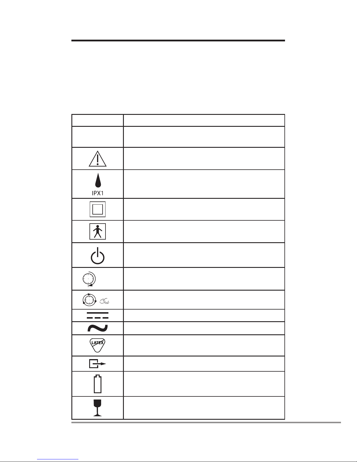
Symbols
The following symbols apply to Aeroneb®Solo nebulizer and
Aeroneb®Pro-X controller. These symbols appear on the back
of the control module and on the packaging:
Table 1: Aeroneb®Solo System Symbols
Symbol Meaning
AP-YYXXXX Serial number, where YY is the year of
manufacture and XXXX is the serial number
Attention, consult accompanying documents
Degree of protection against dripping water
Class II equipment per IEC/EN 60601-1
Type BF equipment per IEC/EN 60601-1
On/Off power button (standby)
30 (Min.) 30 minute operating mode
8
Continuous operating mode (International)
Control Module Input – DC voltage
Control Module Output – AC voltage
Does not contain natural rubber latex
Output
Battery status indicator
Fragile, handle with care

10 Aeroneb®Solo System Instruction Manual
Table 1: Aeroneb®Solo System Symbols
Symbol Meaning
–20 oC
+60 oCTransient storage temperature limitations
–20 °C to +60 °C.
Keep dry.
Rx Only Federal (US) law restricts this device to sale
by or on the order of a physician.
US
Classied by TUV with respect to electric
shock, re and mechanical hazards.
This device complies with the requirements
of the Medical Devices Directive
(93/42/EEC).
NON
STERILE
Non-Sterile
Consult Instructions for Use
Use by (YYYY-MM)
Manufacturer
Batch Code
S
N
Serial Number
REF
Catalogue Number
Single Patient Use, Do not reuse
Aeroneb®Solo System Instruction Manual 11
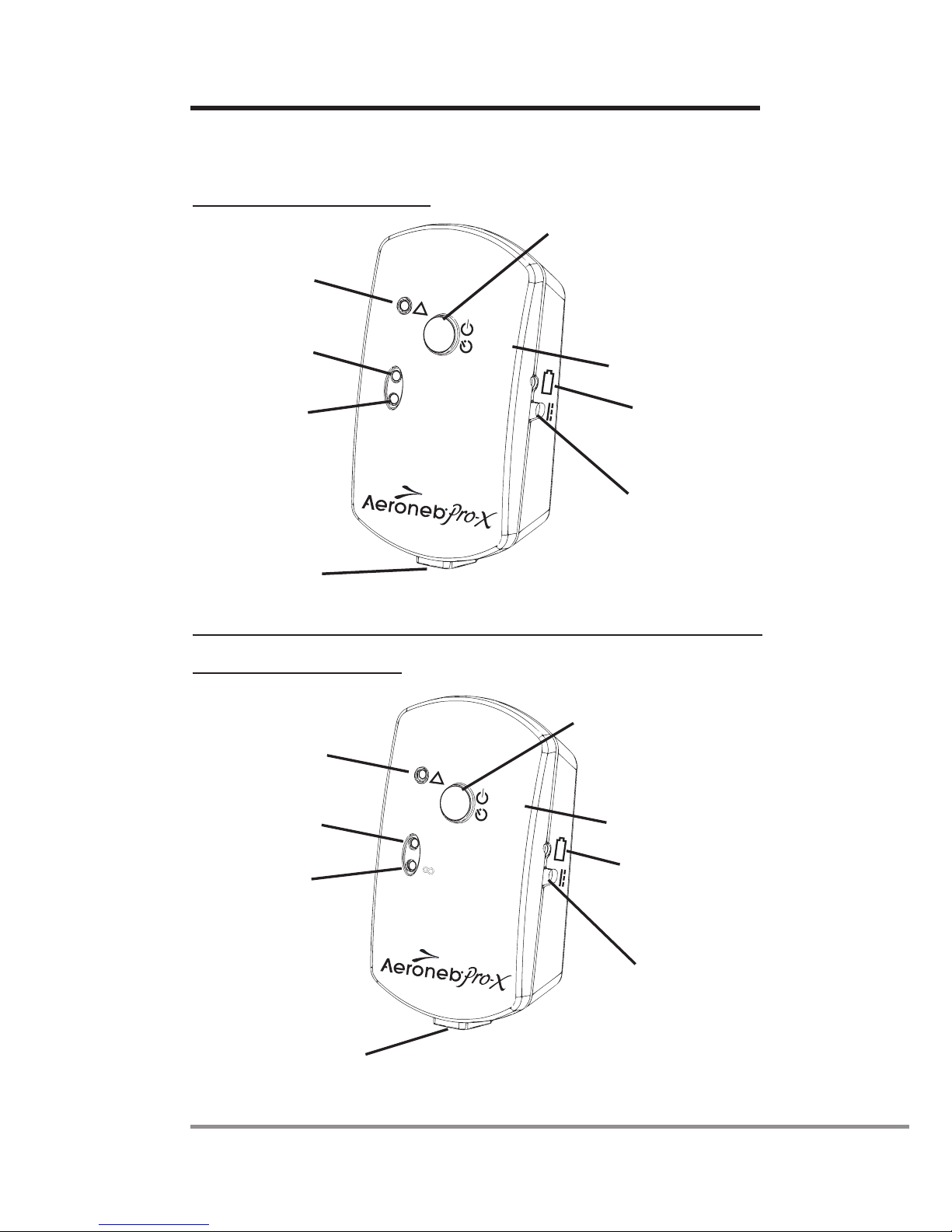
Controls and indicators
North American Controller
Fault Indicator
30 Min.
Indicator
Continuous
Mode Indicator
On/Off Power
Timer Selection
Battery Status
Indicator
9V D.C. Input
Control Module
Cable Input
30 Min.
Continuous Mode
On/Off
!
Timer
International Controller
Fault Indicator
30 Min.
Indicator
Continuous
Mode Indicator
On/Off Power
Timer Selection
Battery Status
Indicator
9V D.C. Input
Control Module
Cable Input
30
On/Off
!
Timer
8
Figure 2: Aeroneb®Pro-X controls and indicators
12 Aeroneb®Solo System Instruction Manual
Table 2: Aeroneb®Pro-X controls and indicators
Control/indicator Function
30 Min. indicator Green (steadily lit) = 30 minute
nebulization cycle on
Green (ashing) = Low battery power
Nebulizer unit automatically powers off
after 30 minutes have elapsed
Continuous
indicator
Green (steadily lit) = Continuous
nebulization cycle on
Nebulizer unit does not power off
automatically
Fault indicator Amber (steadily lit) = Aeroneb®Solo
Nebulizer disconnected from
Aeroneb®Pro-X controller.
Amber (ashing) = Aeroneb®Pro-X
drive voltage error
On/Off power
button
Pressing and immediately releasing
selects the 30 minute nebulization
cycle
Pressing and holding for at least
three seconds selects the continuous
nebulization cycle
Pressing during nebulization turns off
power to the nebulizer
Battery status
indicator
Green = Battery fully charged
Amber = Battery charging
No light = Battery in operation

Aeroneb®Solo System Instruction Manual 13
Warranty
Aerogen warrants that the Aeroneb®Solo nebulizer shall be
free from defects of workmanship and materials for a period of
the dened life of the nebulizer when used in accordance with
this instruction manual.
The Aeroneb®Pro-X Control Module and AC/DC Adapter are
warranted against defects in manufacturing for a period of two
years from the date of purchase. All warranties are based on
typical usage, detailed below.
Life of Product
As with all active electronic components, the Aeroneb®Solo
nebulizer unit has a dened life. In the case of Aeroneb®Solo,
the life of the nebulizer unit has been validated for intermittent
use for a maximum of 28 days based upon a typical usage
prole of 4 treatments per day.
For continuous use the life of the Aeroneb®Solo nebulizer unit
and the continuous nebulization tube set have been validated
for use for a maximum of 7 days.
The user should note that use in excess of these periods is
not validated by Aerogen.
14 Aeroneb®Solo System Instruction Manual
Assembly and Installation
Intermittent Nebulization
Perform a functional test of the Aeroneb®Solo before use
as described in the Functional Test section of this manual
(See page 30).
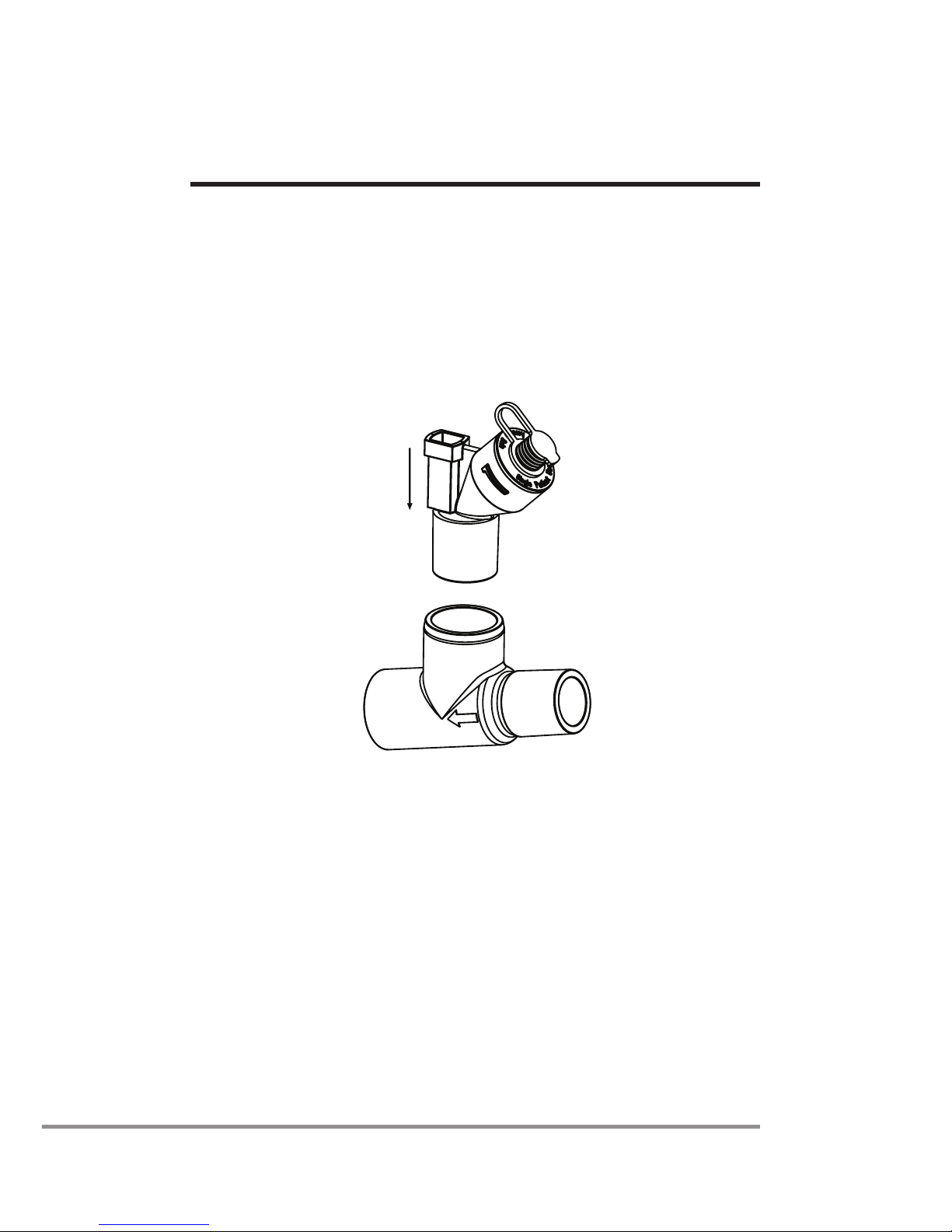
1. Connect the nebulizer unit to the T-piece by pushing the
nebulizer unit rmly onto the T-piece (Figure 3).
Figure 3: Connecting nebulizer unit to T-piece
2. Insert the nebulizer and the T-piece into the breathing
circuit with the arrow on the T-piece pointing in the
direction of the air-ow within the circuit.
3. Connect the Aeroneb®Pro-X control module to the
Aeroneb®Solo nebulizer unit using the nebulizer cable
as shown in Figure 4.
Table of contents
Other Aeroneb Respiratory Product manuals


