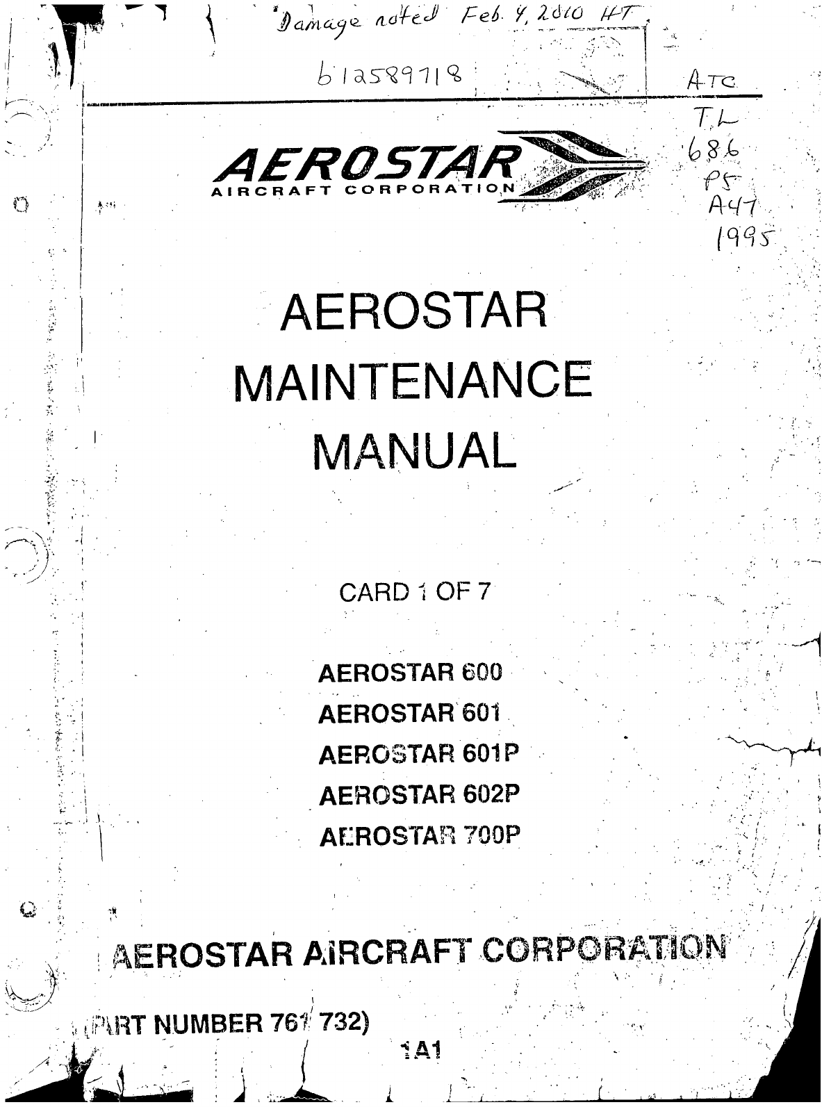
Aerostar Aircraft Corporation 600 User manual
1
AIRCRAFT
CORPOR
A'T
1
O^t^'j^j^^^j^^^^--
Arc
AEROSTAR
MAINTENANCE
MANUAL
CARD
1
OF 7
AEROSTAR
AEROSTAR 601
AEROSTAR 601P
AEROSTAR 602P
AEROSTAR 700P
Q
^T NUMBER 761 732)
1A1
1
J

AEROSTAR
AIRGRAFT
600/601/601P/602P/700P
MAINTENANGE,
MANUAL
INTRODUCTION.
This
AEROSTAR
AIRCRAFT Maintenance Manual is prepared in accprdan.ce,withtheGAMA (General
Aviation Mariufacturers Association) format. This maintenance manual is divided intoVarious Groups wh1c
enable a broad separation of contents (Chapters)
within
each group.
The various Chapters are broken down into major systems such as Electrical Power,, Flight Controls,
Fuel,
Landing Gear, etc. The System/Chapters are arranged more or less alphabetically rather,than.by.prece-
dence
or importance. All System/Chapters are
.assigned
a number, which becomes the firstvelement of a stan-
dardized numbering system. Thus the element "32" of the number series
32-00-(Db,
refers to the.System/Chapter
on
"Landing Gear." All information pertaining to the landing gear
will
be covered in this Systenn/Chapter. :
The major Systeni/Chapters are then broken down into
Sub-System/Sectiohs.
These sections.are identi-
fied by the second element of the standardized numbering system. The number "40" of the basic number series
32r40-00
is for the "Wheels and Brakes" portion of the landing gear. •
The individual units
within
a Sub-System/Section may be identified by a third element of the standardized
numbering
system,
such as
32-40-01.
This number
could
be assigned by the-manufacturer to fit the coverage
requirements'of the publication.
Example:
CHAPTER/SYSTEM
LANDINGGEAR
SUB-SYSTEMS
WHEELSANDBRAKES
32-40-01
INDIVIDUAL
UNITS
NOSEWHEELREMOVAL
This
manual does not contain hardware callouts for installation. Hardware callouts are only indicated
where
a special application is required. To confirm the correct hardware
used,
refer to the Parts Catalog
P/N 761 731, and FAR 43 for proper utilization.
1A2
Introduction
Page
-1
Issued: June 1, 1995
V
AEROSTAR
AIRCRAFT
600/601/601P/602P/700P
MAINTENANCE
MANUAL
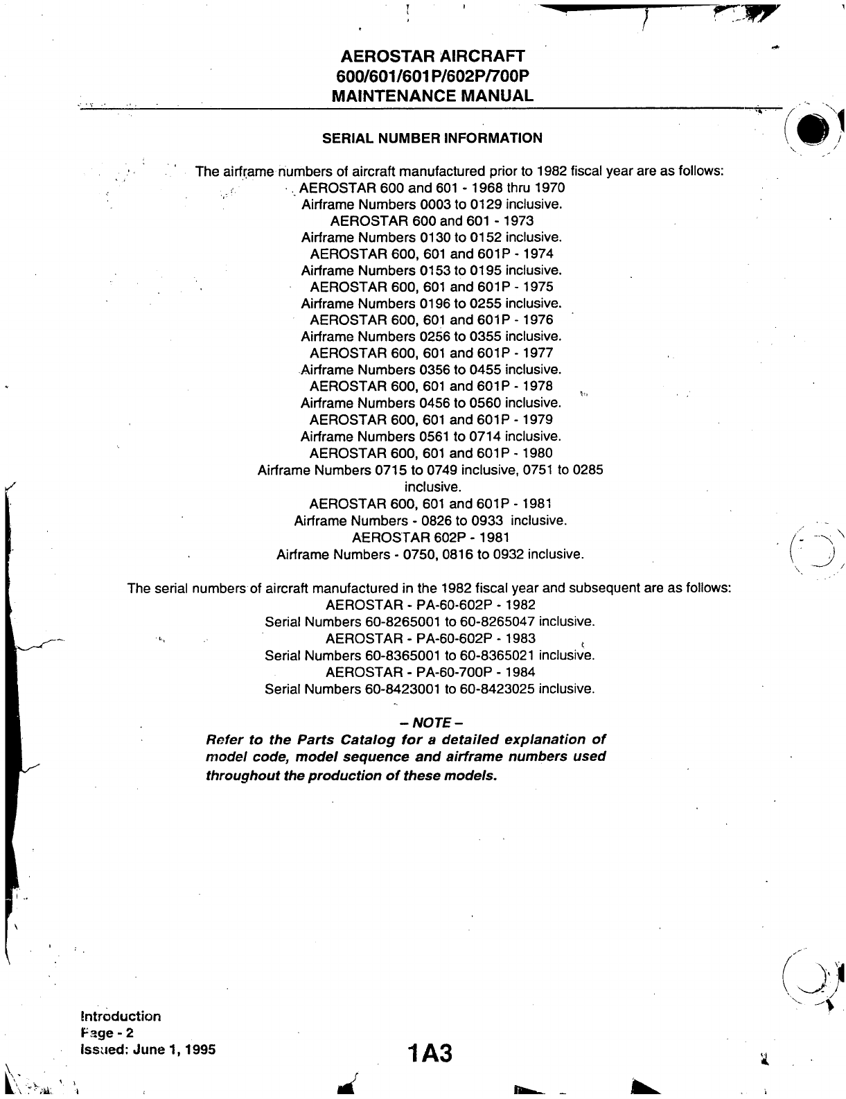
SERIAL
NUMBER INFORMATION
The
airframe numbers
of
aircraft manufactured prior
to 1982
fiscal year
are
as follows:
AEROSTAR
600
and 601
-
1968 thru
1970
Airframe Numbers
0003 to
0129
inclusive.
AEROSTAR
600
and
601
- 1973
Airframe Numbers
0130 to 0152
inclusive.
AEROSTAR
600,
601
and 601P
-1974
Airframe Numbers
0153 to
0195
inclusive.
AEROSTAR
600,
601
and
601P
-1975
Airframe Numbers
0196 to 0255
inclusive.
AEROSTAR
600,
601
and 601P
- 1976
Airframe Numbers
0256 to 0355
inclusive.
AEROSTAR
600,
601
and 601P
-1977
Airframe Numbers
0356 to 0455
inclusive.
AEROSTAR
600,
601
and
601P
- 1978
Airframe Numbers
0456 to 0560
inclusive.
AEROSTAR
600,
601
and 601P
- 1979
Airframe Numbers
0561
to 0714
inclusive.
AEROSTAR
600,
601
and 601P
-1980
Airframe Numbers
0715 to
0749
inclusive,
0751 to 0285
inclusive.
AEROSTAR
600,
601
and 601P
-1981
Airframe Numbers
-
0826 to 0933
inclusive.
AEROSTAR
602P-
1981
Airframe Numbers
-
0750, 0816
to
0932
inclusive.
The
serial numbers
of
aircraft manufactured
in the 1982
fiscal year and subsequent
are as
follows:
AEROSTAR
-
PA-60-602P
- 1982
Serial
Numbers
60-8265001 to 60-8265047
inclusive.
AEROSTAR-PA-60-602P-
1983 ,
Serial
Numbers
60-8365001 to 60-8365021
inclusive.
AEROSTAR
-
PA-60-700P
- 1984
Serial
Numbers
60-8423001 to 60-8423025
inclusive.
-NOTE-
Refer
to the
Parts
Catalog
for a
detailed
explanation
of
model
code,
model
sequence
and
airframe
numbers used
throughout
the
production
of
these
models.
Introduction
Page-2
issued:
June
1,1995
1 A3

AEROSTAR
AIRCRAFT
600/601/601P/602P/700P
MAINTENANCE
MANUAL .
AEROFICHE
EXPLANATION AND REVISION
STATUS
Maintenance manual information incorporated in
ttiis
set of Aerofictie cards is arranged in accordance
witti
ttie
specifications of Aerofictie adopted by
ttie
GenerarAviation Manufacturers
Association.
Information
com-
piled in
ttiis
Aerofictie Maintenance Manual is
kept
current by revisions distributed periodically, ttiese revisions
supersede
all previous revisions and are complete Aerofiche card replacements and shalhsupersede Aerofiche
cards
of the same number in the set.
Identification
of revised material:
Revised
text
and illustrations are indicated by a black verticalline along the left-hand margin of the frame, oppo-
site revised and added material. Revision lines indicate only current revisions
with
changes and additions to exist-
ing
text
and illustrations. Changes in capitalization, spelling, punctuation, indexing, the physical location of the
material, or complete page additions are not identified by revision lines.
A
reference and record of the
material
revised is included in each chapter's Table of Contents/Effectivity. The
code
used in the effectivity colurhns of eachchapter is defined as follows:
TA-BLE
OF
CONTENTS/EFFECTIVITY
CODES
Original Issue: None
First
Revision:
Revision Identification, (1R Month-Year)
Second
Revision: Revision Identification, (2R Month-Year)
All
subsequent revisions
will
follow
with
consecutive revision numbers
such
as 3R, 4R, etc., along
with
the appropriate month-year.
Added
Subject: Revision Identification, (A Month-Year)
Revisions
to Maintenance Manual 761 732 reissued June
1,1995,
are as follows:
Revisions
Date
Aerofiche Card Effectivity
Reissued
June
1,1995
1, 2, 3, 4, 5, 6, and 7
the
date
on Aerofiche cards must not be earlier than the
date
noted for the respective card effectivity.
Consult
the latest Aerofiche card in this series for current Aerofiche card effectivity.
1A4
Introduction
Page-3
Issued: June
1,1995
AEROSTAR
AIRCRAFT
600/601/601P/602P/700P
MAINTENANCE
MANUAL
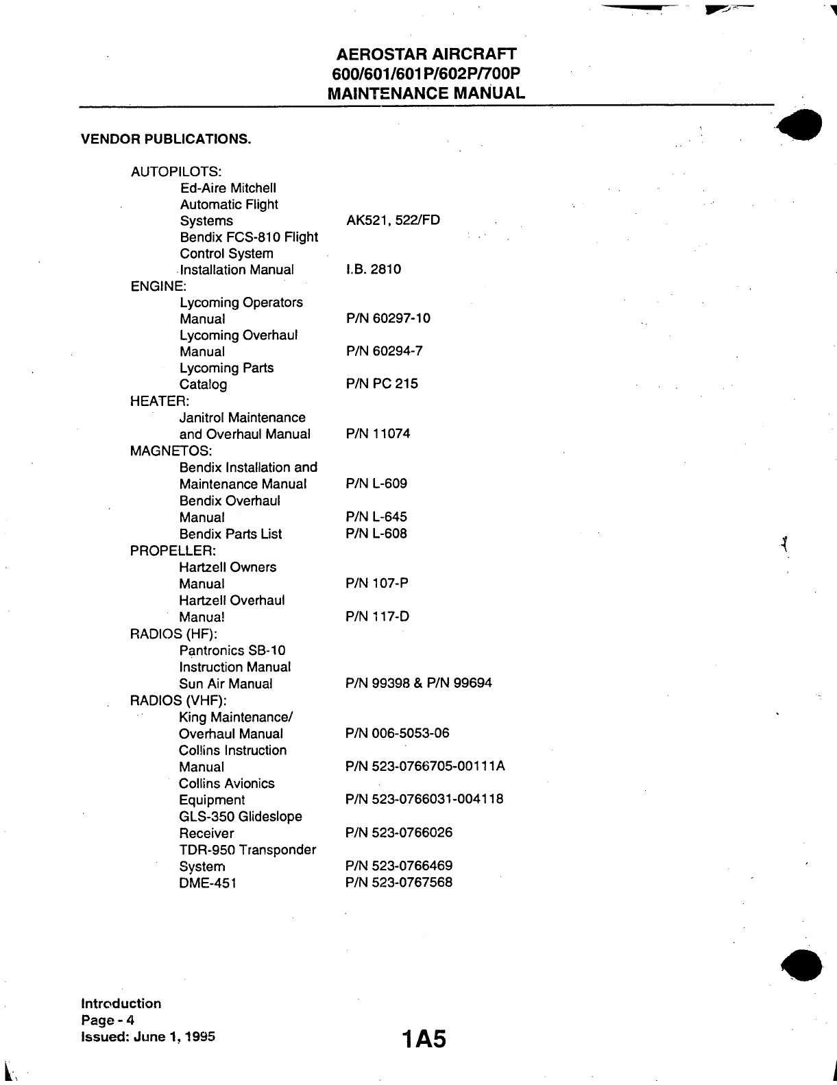
VENDOR
PUBLICATIONS.
AUTOPILOTS:
Ed-Aire
Mitchell
Automatic Flight
Systems
Bendix
FCS-810 Flight
Control
System
Installation
Manual
ENGINE:
Lycoming
Operators
Manual
Lycoming
Overhaul
Manual
Lycoming
Parts
Catalog
HEATER:
Janitrol Maintenance
and
Overhaul Manual
MAGNETOS:
Bendix
Installation
and
Maintenance Manual
Bendix
Overhaul
Manual
Bendix
Parts List
PROPELLER:
Hartzell Owners
Manual
Hartzell Overhaul
Manual
RADIOS
(HF):
Pantronics
SB-10
Instruction Manual
Sun
Air
Manual
RADIOS
(VHF):
King
Maintenance/
Overhaul
Manual
Collins
Instruction
Manual
Collins
Avionics
Equipment
GLS-350
Glideslope
Receiver
TDR-950 Transponder
System
DME-451
AK521,
522/FD
I.B. 2810
P/N
60297-10
P/N
60294-7
P/N PC
215
P/N
11074
P/N
L-609
P/N
L-645
P/N
L-608
P/N
107-P
P/N
117-D
P/N
99398 & P/N 99694
P/N
006-5053-06
P/N
523-0766705-00111A
P/N
523-0766031-004118
P/N
523-0766026
P/N
523-0766469
P/N
523-0767568
Introduction
Page
- 4
Issued:
June
1,1995
1A5

Addendum
to
Aerostar
Maintenance
Manual
Please
note:
Conair
Aviation
Ltd.
fias
added
a section to the end of
ttiis
manual
called:
CAL-WMS
This addendum
CAL-WMS
is a
Alternator
Wiring
Modification
for the
Wiring
l\/lanual
Supplement
issued by Conair Aviation Ltd.
As per the instructions of Dick Kopp, Sr. Inspector, on the
8'"
of December, 1998,
this
section is to incorporated
into
the
Aerostar
Maintenance
Manual
and
will
act as a supplement
this
manual.
Any revision or additions, amendments, etc. of
this
section of the Maintenance
Manual are to be updated on the Record of Revisions as applicable.
This addendum is dated the 8'" of
January,
1999 at
Abbotsford,
British
Columbia by the Technical
Library.

Conair
Aviation Ltd. Technical Library
^.Record
of Revisions (as recorded by Conair)
^
^
Revision Date
Page(s)
Inserted Inserted By Date Inserted
0 u
/
I
h:\publicat\library\REVCOVER.XLS NOTE: Always refer
to
manufactures status report for latest revisions!
AEROSTAR
AIRCRAFT
600/601/601P/602P/700P
MAINTENANCE
MANUAL
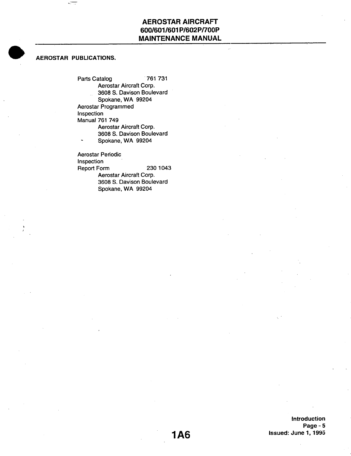
AEROSTAR
PUBLICATIONS.
Parts Catalog
761 731
Aerostar
Aircraft
Corp.
3608
S.
Davison Boulevard
Spokane,
WA 99204
Aerostar Programmed
Inspection
N^anual
761 749
Aerostar
Aircraft
Corp.
3608
S.
Davison Boulevard
Spokane,
WA 99204
Aerostar Periodic
Inspection
Report Form
230 1043
Aerostar
Aircraft
Corp.
3608
S.
Davison Boulevard
Spokane,
WA 99204
1A6
Introduction
Page
••
5
Issued: June
1, 1993
AEROSTAR
AIRCRAFT
600/601/601P/602P/700P
MAINTENANCE
MANUAL
VENDOR-SUPPLIER
INFORMATION.
A
partialiist
of
companies,
tfieir
address and pfione numbers
are
provided
to
aid service personnel
in
obtaining information about components
not
manufactured
by
Aerostar Aircraft Corporation.
C
& D
Airmotive Products Heaters
-
Environmental Systems
4445
Shiawnee Road
Berrien Springs,
Ml 49103
(616) 695-7469
Bendix/King Radio Corporation
All
King and Bendix Avionics
400
Northi Rogers Road
Olattie,
Kansas
66061
(913) 782-0400
Edo-Aire
Mitcfiell Autopilots
P.O.
Box
610
Mineral Wells, Texas
76007
(817) 325-2517
Textron Lycoming Williamsport Engines
Division
652
Oliver
Street
Williamsport,
PA 17701
Hartzell
Propeller,
Inc.
Propellers, Governors
Piqua,
Ofiio
45356
(513) 773-7411
Scott Aviation Oxygen Components
225
Erie
Street
Lancaster,
New
York
14086
(716)683-5100
Collins
Radio Group Avionics
350
Collins Road
NE
Cedar Rapids,
lA 52406
Sun
Air
Electronics,
Inc.
Radios
(HF)
3101 S.W. 3rd
Avenue
Ft. Lauderdale, Florida
33315
Introduction
Page
- 6
Issued: June
1,1995
1A7
AEROSTAR
AIRCRAFT
600/601/601P/602P/700P
MAINTENANCE MANUAL
THIS
PAGE
INTENTIONALLY LEFT BLANK
1A8

AEROSTAR
AIRCRAFT
600/601/601P/602P/700P
MAINTENANCE MANUAL
THIS
PAGE
INTENTIONALLY LEFT BLANK
1A9

AEROSTAR
AIRCRAFT
600/601/601P/602P/700P
MAINTENANCE MANUAL ^
GAMA
SYSTEM/CHAPTER
INDEX
GUIDE
-NOTE-
The
following
Chapters are not covered
within
this
Maintenance
Manual:
31, 37, 38, 49, 60, 70, 72, 75, 83, 95.
SYST
SUB-SYST AEROFICHE
CHAP
SECTION TITLE
GRID
NO.
4 AIRWORTHINESS
LIMITATIONS
1B5
5
TIME
LIMITS/MAINT
CHECKS
IBS
6
DIMENSIONS
AND
AREAS
1017
7
LIFTING
AND SHORING
IDIO
8 LEVELING AND
WEIGHING
1E3
9 TOWING AND
T/VXIING
1E11
10 PARKING AND MOORING 1E21
11 REQUIRED PLACARDS 1F4
12 SERVICING 1G11
20 STANDARD PRACT - AIRFRAME 117
21 ENVIRONMENTAL SYSTEM & PNEUMATIC
SYSTEM
, 2B4
22 AUTOFLIGHT 211
23 COMMUNICATIONS 215 . ,
.
- - ^
24 ELECTRICAL POWER V 385
25 EQUIPMENT/FURNISHINGS
3C22
26 FIRE PROTECTION
3E20
27 FLIGHT CONTROLS ' 3F2
28 FUEL 312
IntroducHon
Pago - 9
Issued: .June 1,
•i995
/
I
t
AEROSTAR AIRCRAFT
600/601/601P/602P/700P
MAINTENANCE MANUAL
GAMA SYSTEM/CHAPTER
INDEX
GUIDE
(cont)
SYSJ
CHAP
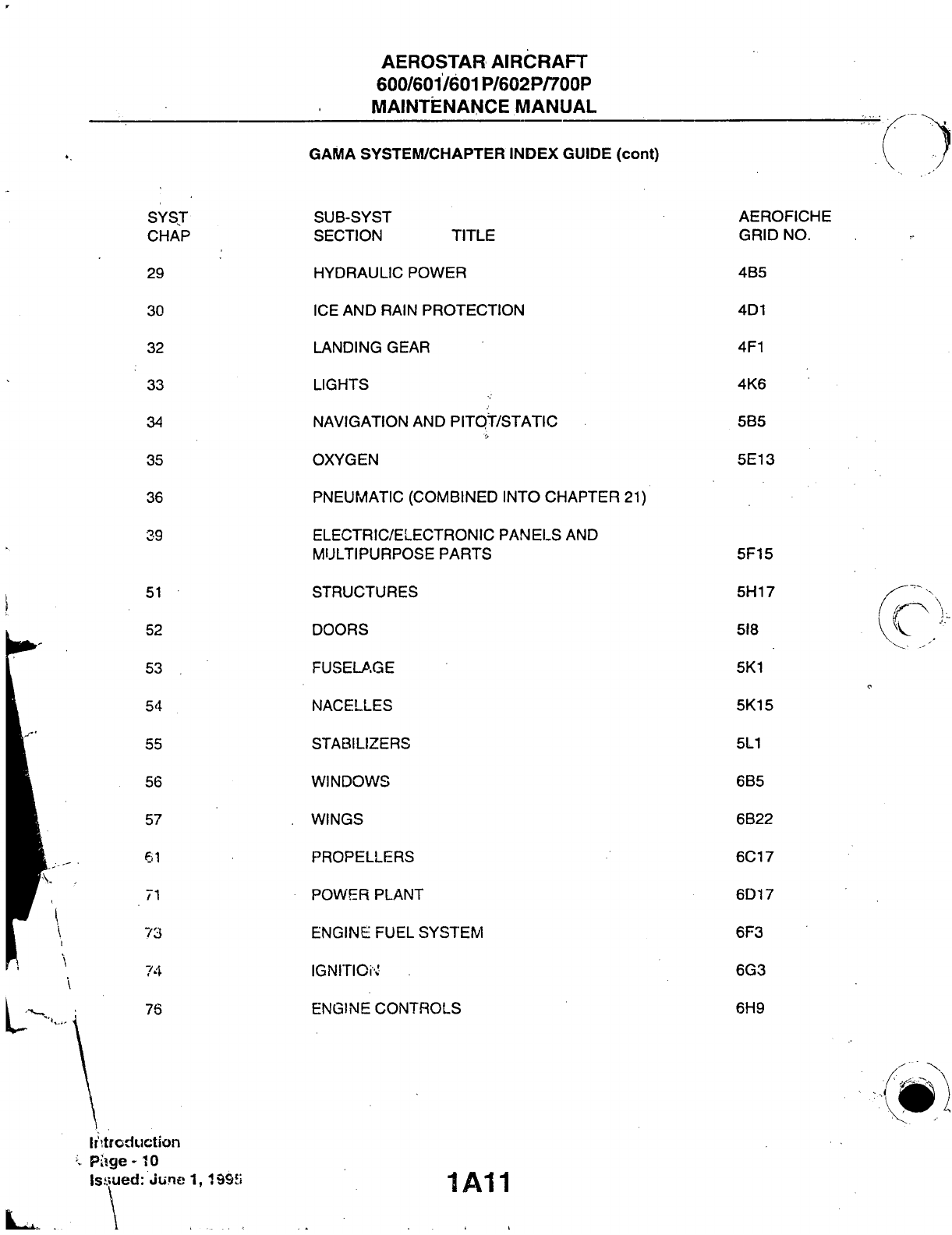
29
30
32
33
34
35
36
39
51
52
53
,
54
55
56
57
61
71
73
74
76
SUB-SYST
SECTION
TITLE
HYDRAULIC POWER
ICE AND
RAIN
PROTECTION
LANDING
GEAR
LIGHTS
NAVIGATION
AND
PITQT/STATIC
OXYGEN
PNEUMATIC
(COMBINED
INTO
CHAPTER
21)
ELECTRIC/ELECTRONIC PANELS AND
MULTIPURPOSE PARTS
STRUCTURES
DOORS
FUSELA.GE
NACELLES
STABILIZERS
WINDOWS
WINGS
PROPELLERS
POWER PLANT
ENGINE
FUEL SYSTEM
IGNITIOi\'
ENGINE
CONTROLS
AEROFICHE
GRID
NO.
4B5
4D1
4F1
4K6
5B5
5E13
5F15
5H17
518
5K1
5K15
5L1
6B5
6B22
6C17
6D17
6F3
6G3
6H9
Irtr
eduction
Piige-10
ls.'.5ued:
June
1,19911
1A11

AEROSTAR
AIRCRAFT
600/601/601P/602P/700P
MAINTENANCE
MANUAL
GAMA
SYSTEM/CHAPTER
INDEX
GUIDE
(cont)
SYST
SUB-SYST AEROFICHE
CHAP
SECTION TITLE
GRID
NO.
77 - ENGINE
INDICATING
611
78 EXHAUST 6119
79 OIL 6J3
80 STARTING
6J20
81 TURBINES . 7B5
91 CHARTS AND
WIRING
DIAGRAMS 7C9
) :
Introduction
Page -11
"lAIZ
Issued: June
1,1995
AEROSTAR
AIRCRAFT
600/601/601P/602P/700P
MAINTENANCE
MANUAL
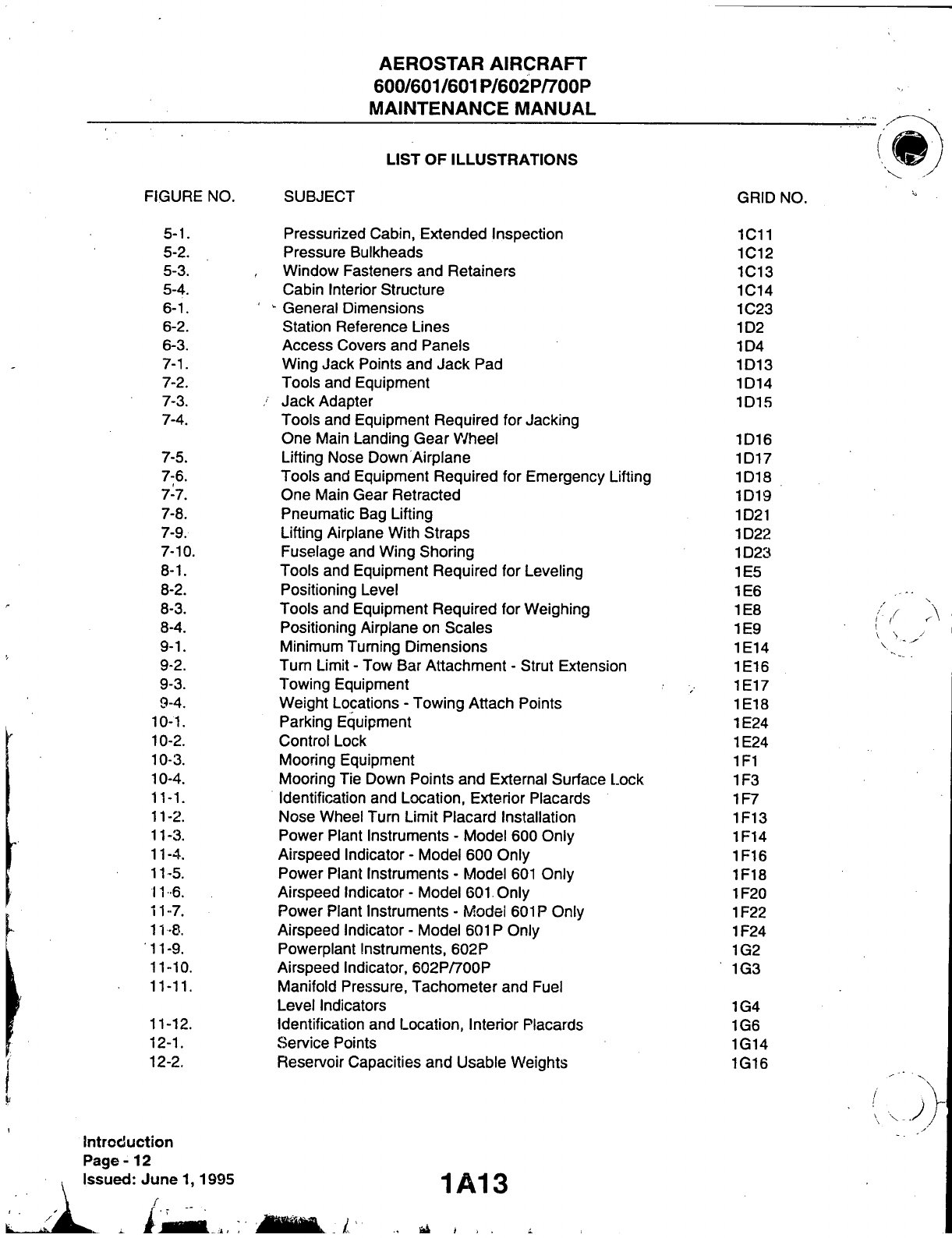
LIST OF ILLUSTRATIONS
FIGURE
NO.
SUBJECT
GRID NO.
5-1.
Pressurized
Cabin, Extended Inspection 1011
5-2.
Pressure
Bulkheads 1012
5-3. Window Fasteners and Retainers 1013
5-4.
Cabin
Interior
Structure 1C14
6-1.
'
General Dimensions 1023
6-2. Station Reference Lines 1D2
6-3.
Access
Covers and Panels 1D4
7-1. Wing Jack Points and Jack Pad 1D13
7-2.
Tools
and Equipment 1D14
7-3.
/
Jack Adapter 1D15
7-4.
Tools
and Equipment Required for Jacking
One Main Landing Gear V/heel 1D16
7-5. Lifting Nose Down Airplane 1D17
7-6.
Tools
and Equipment Required for Emergency Lifting 1D18
7-7. One Main Gear Retracted 1D19
7-8. Pneumatic Bag Lifting 1D21
7-9. Lifting Airplane
With
Straps 1D22
7-10.
Fuselage
and Wing Shoring 1D23
8-1.
Tools
and Equipment Required for Leveling 1E5
8-2. Positioning Level 1E6
8-3.
Tools
and Equipment Required for Weighing 1E8
8-4. Positioning Airplane on Scales 1E9
9-1. Minimum Turning Dimensions 1E14
9-2. Tum Limit - Tow Bar Attachment - Strut Extension 1E16
9-3. Towing Equipment 1E17
9-4. Weight Locations - Towing Attach Points 1E18
10-1. Parking Equipment 1E24
10-2. Control Lock 1E24
10-3. Mooring Equipment 1F1
10-4. Mooring Tie Down Points and External Surface Lock 1F3
11-1.
Identification
and Location, Exterior Placards 1F7
11-2.
Nose
Wheel Turn Limit Placard
Installation
1F13
11-3. Power Plant
Instruments
- Model 600 Only 1F14
11-4.
Airspeed
Indicator
- Model 600 Only 1F16
11-5. Power Plant
Instalments
- Model 601 Only 1F18
11-6.
Airspeed
Indicator
- Model 601 Only 1F20
11-7. Power Plant
Instruments
- Model 601P Only 1F22
11-8.
Airspeed
Indicator
- Model 601P Only 1F24
11-9. Powerplant Instruments,
602P
1G2
11-10.
Airspeed
Indicator,
602P/700P
1G3
11-11.
Manifold Pressure, Tachometer and Fuel
Level
Indicators 1G4
11-12.
Identification
and Location,
Interior
Placards 1G6
12-1.
Sen/ice
Points 1G14
12-2. Reservoir Capacities and Usable Weights 1G16
Introduction
Page-12
Issued: Junel, 1995 1 A1 3

AEROSTAR
AIRCRAFT
600/601/601P/602P/700P
MAINTENANCE
MANUAL
LIST OF ILLUSTRATIONS
(cont)
FIGURE NO.
SUBJECT
,
GRID
NO.
12-3. Fuel Drain Hose Connections 1G19
12-4. Oil Selection 1G22
12-5. Oil Filter Assembly 1G23
12-6. Hydraulic Reservoir, Accumulator and Brake Resen/oir 1H1,,
12-7. Tire Pressures 1H3
12-8. Batteries 1H4
12-9.
Alcohiol
Deice Reservoir 1H5
12-10.
Nose Landing Gear Service Points 1H7
12-11.
Main Landing Gear Service Points 1H10
12-12.
Dry Nitrogen Equipment for Sen/icing Main Landing
Gear Struts 1H10
12-13.
Oxygen System 1H11
12-14.
Lubrication Points 1H14
12-15.
Lubrication Chart (Landing Gear, Nose) 1H15
12-16.
Lubrication Chart (Doors, Emergency
Exit)
1H19
12-17.
Lubrication Chart
(Main
Landing Gear, Flap Tracks,
Doors,
Trim Tabs and Console) 1H21
12-18.
Lubrication Chart
(Flight
Controls) 1H23
12-19.
Suggested Cleaners 111
12-20.
Suggested Polish and Wax 112
12-21.
Suggested Plastic Polish 112
20-1. Cherrylock Rivet Removal 1111 '
20-2. Hose/Line Markings 1113
20-3. Flareless - Tube Fittings 1114
20-4. Maximum Distance
Between
Supports for Fluid Tubing 1115 .
20-5. Maximum Allowable Resistance Values 1116
20-6. Sealant Application -
Wire
Bundles and Connectors 1121
20-7. Sealant Curing
Information
1123
20-8. Sealant Applications 1J2
20-9. Sealant Filling of Cavities 1J4 •
20-10.
Fillets, Rivets, Nuts and Bolts Sealing 1J6
20-11.
Rework
of Damaged or Faulty Fillet 1J7
20-12.
Duct Sealing Methods 1J8
20-13.
Application vs
Material
Use 1J10
20-14.
Sealant Mixing Ratio - . 1J11
20-15.
Firewall
Sealing 1J13 •
20-16.
Finish
Coating Precaution Areas 1J16
20-17.
Spray
Patterns
1K3
20-18.
Improper
Spraying 1K5
20-19.
Proper and
Improper
Method 1K6
20-20.
Spraying Comers 1K6
21-1. Environmental Systems Schematic 2C1
21-2. Flow Control Assembly
(601P)
2C10
21-3. Pressurization Systems Distribution Components 2C14
21-4. Cabin Leak Test Set Up 2C19
21-5. Pneumatic System Schematic 2D3
1A14
Introduction
Page-13'
issued:
June
1,1995

AEROSTAR
AIRCRAFT
600/601/601P/602P/700P
MAINTENANCE
MANUAL
LIST OF ILLUSTRATIONS
(cont)
FIGURE NO.
SUBJECT
GRID
NO.
21-6. Pneumatic System Components 2D5
21-7. Pneumatic System Air Pumps 2D8
21-8. Pneumatic System Test Setup 2D15
21-9. Door Seal Pressure Switch Test Setup 2D21
21-fb.
Vent Fan Blower and Plenum Box Assembly 2E1
21-11.
R/H Distribution Duct Assembly 2E5
21-12.
L/H Distribution Duct Assembly 2E7
21-13.
Fan Blower
(Instrument
Panel Radios) 2E11
21-14.
Pressurization Controls 2E12
21-15.
Outflow and Safety Valve 2E15
21-16.
Nose Landing Gear Squat Switch 2E18
21-17.
Cabin Altitude Controller Resetting Procedure 2E21
21-18.
Heater,
Blower and Plenum Assemblies 2F5
21-19.
Combustion Air Blower Assembly 2F15
21-20.
Heater
Relays 2F18
21-21.
Spark Plugs 2F21
21-21
A.
Ground Electrode Fixture
2F22
21-22.
Heat
Duct Switch and Control 2G4
21-23.
Fuel Pump Assembly, Fuel Pressure Regulator and
Shutoff Valve 2G6
21-24.
Regulator and Shutoff Valve Test Setup 2G11
21-25.
Windshield Defrost Blower Assembly 2G12
21-26.
Air
Conditioning System 2G15
21-27.
Compressor
Mounted Sen/ice Valves
(York
Compressor) 2G19
21-28.
Evacuation Hookup 2G19
21-29.
Test Gauge and Manifold Set
2G22
21-30.
Manifold Set Operation
2G23
21-31.
Charging Hookup 2H1
21-32.
Charging Stand 2H4
21-33.
Positioning Sankyo Compressor
Internal
Parts 2H11
21-34.
Fabricated Dipsticks for Compressor
Oil Check 2H12
21-35.
Sankyo Compressor Mounting Angle 2H12
21-36.
Magnetic Clutch
(York
Compressor) 2H16
21-37.
Magnetic Clutch Assembly (Sankyo Compressor) 2H16
23-1.
VHF
Interconnecting Diagram (Collins) 2112
23-2.
VHF
250/251
Communications Transceiver
Interconnect
Wiring Diagram 2113
23-3.
VHF
System Locator 2115
23-4.
VHF
Transceivers and Audio Switching Panel 2117
2?>-5.
PWC-150 Power Converter Locator 2119
23-6.
VHF
COMM-1 Antenna 2121
23-7.
VHF
COMM-2 Antenna 2121
23-8. SB-10 Transceiver Interconnecting Diagram 2J3
Introduction
Page-14
issued:
June
1,1995
1A15
AEROSTAR
AIRCRAFT
600/601/601P/602P/700P
MAINTENANCE
MANUAL
LIST OF ILLUSTRATIONS
(cont)
FIGURE
NO.
SUBJECT
GRID NO.
23-9. SB-10 Transceiver Interconnecting and HF Reel .
Diagram 2J5
23-10.
HF Locator 2J7
23-11.
ASB-100A, HF Interconnecting Diagram 2J20
23-12.
ASB-100A. HF System Locator 2J21
23-13.
Fixed Antenna
Installation
2J23
23-14.
ELT
Installation
2K1
23-15.
Removal of Microptione Switcti 2K6
23-16.
AMR 350 Audio/Marker Panel Controls and
Indicators 2K8
23-17.
Audio/Marker Panel Interconnecting Diagram 2K12
23- 18. Static Disctiarge InsL (TYP) 2K15.
24- 1. AC System 3B18
24-2. Electrical System Locator 3B19
24-3. Jumper Strap
Installation
3B23
24-4. Master Electrical Panel 3C2
24-5. Power Circuit Breakers ' 3C6
24-6. Battery
Installation
3C8
24-7. Equipment Circuit Breakers 3C16
24- 8. Avionics Relay 3C18
25- 1. Seat Arrangement - Standard
Interior
3D4
) 25-2. Seat Arrangement - Executive
Interior
3D5
25-3. Seat Hardware 3D9
25-4. Recline Mectianism
(Left
Center and Left Rear Seats) 3D12
25-5. Recline Mectianism
(Rigtit
Side Seats) 3D13
25-6. Pilot Seat Break-Over Bracket 3D15 ,
25-7. Seat Back Armrest 3D17
25-8. Swivel Seat Break-Over Bracket and "Hydrolok" 3D19
25-9. Swivel Mectianism
3D20
25-10.
Table Assembly 3D21 ,
25-11.
Inertia
Reel (Cover Removed)
3D23
25-12.
Sun Visors
3D24
25-13.
Glarestiield Angle Bracket 3E1
25-14.
Armrest Panel
Installation
3E3
25-15.
Interior
Trim 3E6
25-16.
Application of Double Sided Tape
Attactiing Emergency Exit Window
Moulding 3E12
25-17.
Application of Double Sided Tape Attactiing
Cabin
Door Window Moulding 3E15;-
25-18.
Baggage Compartment Furnishings 3E16
25-19.
Standard Baggage Compartment Light 3E17
25-20.
Covered Baggage Compartment Light 3E18
)
Introduction
Page-15
-j g Issued: June
1,1995
AEROSTAR
AIRCRAFT
600/601/601P/602P/700P
MAINTENANCE
MANUAL
LIST OF ILLUSTRATIONS
(cont)
FIGURE NO.
SUBJECT
GRID
NO.
26-1. Fire Detector
3E24
26-2. Portable Fire Extinguisfier 3F1
27-1. Control Column Assembly 3F14
27-2. Aileron Control Linkage Sctiematic 3F18
27-3. Aileron
Idler
Arm, F.S.
146.80
3F22
27-4. Aileron Bellcrank, F.S.
64.78
3F23
27-5. Aileron Lower Bellcrank, F.S.
202.90
3F24
27-6. Aileron Upper Bellcrank, F.S.
202.90
3G1
27-7. Aileron Bellcrank, W.S.
153.00
3G2
27-8. Rudder Pedal Assembly 3G6
27-9. Rudder Control Linkage Sctiematic 3G8
27-10.
Rudder Torque Tube 3G11
27-11.
Rudder Bellcrank, F.S.
77.60
3G13
27-12.
Rudder Bellcrank, F.S.
97.00
3G14
27-13.
Rudder
Idler
Arm, F.S.
202.80
3G15
27-14.
Rudder
Idler
Arm, F.S.
330.90
3G16
27-15.
Rudder Torque Tube Free-Play Ctieck 3G18
27-16.
Rudder Trim Controls
3G20
27-17.
Elevator Control Linkage Schematic
3G22
27-18.
Elevator Fonward Torque Tube Assembly
3G24
27-19.
Elevator Aft Torque Tube 3H1
27-20.
Elevator Bellcrank, F.S.
64.87
3H4
27-21.
Elevator
Idler
Arm, F.S.
146.80
3H5
27-22.
Elevator
Idler
Arm, F.S.
202.80
3H6
27-23.
Elevator
Idler
Arm, F.S.
330.90
3H7
27-24.
Elevator Torque Tube Free-Play Check 3H8
27-25.
Elevator Trim Controls 3H11
27-26.
Flap Position Transmitter (L.
Wing)
3H15
27-27.
Flap Rigging Check 3H16
27-28.
Linkage Carry-Through
Boots.
F.S.
176.88
(TYP.)
3H20
27-29.
Stall Waming System
(700P
Only)
3H23
27-30.
Lift
Transducer Force Applicator Kit 311
28-1. Fuel System Schematic 3111
28-1 a. Fuel System Schematic for Option
#260
3111
28-2. Component Location 3112
28-3. Fuel System,
Detail
A, B, C and D 3113
28-4. Fuel Leak Size
Patterns
: 3120
28-5. Fuel Leak Evaluation 3121
28-6. Pull Force Measurement
(Shaw
Aero Filler Cap Only) 3123
28-7. Control Station and Manometer Setup 3J1
28-8. Wing Tank - As Viewed From Top 3J4
28-9.
Vent
System 3J7
28-10.
Fuselage Fuel Tank 3J9
28-11.
Control Station and Manometer Setup, Fuselage
Tank Pressure Test 3J12
Introduction
Page-16
Issued: June
1,1995
1A17

AEROSTAR
AIRCRAFT
600/601/601P/602P/700P
MAINTENANCE
MANUAL
LIST OF ILLUSTRATIONS
(cont)
FIGURE NO.
SUBJECT
GRID
NO.
28-12.
Fuel Sumps (A/F 0001
-0485)
3J14
28-13.
Fuel Sumps (A/F
0486
& Up) 3J17
28-14.
Boost
Pump, Filter, Flow Transducer and Sump
Drain Valve 3J23
28-15.
Signal Conditioner 3K8 '
29-1. Hydraulic System Schiematic 4B10
29-2. Main Hydraulic Power Components - Locations
and
Identification
4B12
29-3. Component Locator (Ctianging Fluid) 4B17
29-4. Hydraulic Reservoir, Pressure Regulator and
Relief Valve
4B23
29-5. Hydraulic Stiutoff Valve 4C1
29-6. Engine Driven Hydraulic Pump and Ground
403' r.
Service Unit Connection 403' r.
29-7. Pressure Regulator and Relief Valve 4C5 '
29-8. Accumulator 4C8
29-9. Auxiliary Hydraulic Sctiematic 4C11
29-10.
Electrical Component Location and Sctiematic 4C12
29-11.
Auxiliary Hydraulic Pump
Installation
4C20
30-1. Surface Deicing System 4D14
30-2.
Installing
Deicer Boot 4D16 -
30-3. Surface Deicing System Timer 4D18
30-4. Deice Components in Left Wheel
Well
4D19
30-5. Test Pressure Gauge
Installation
4D20
30-6.
Pitot
Head
4D22
30-7.
Alcohol
Shutoff Valve
4D24
30-8.
Alcohol
Windshield Deicing System 4E3
30-9.
Alcohol
Pump 4E5
30-10.
Electric Windshield
Anti-Ice
Panel 4E8
30-11.
Detail
of Electric Windshield
Anti-Ice
Panel 4E8 '
30-12.
Propeller Deicing System 4E11
30-13.
Placement of Deicer Onto Propeller Blade 4E13
30-14.
Application of Filler/Positioning Nylon Strap 4E14
30-15.
Rolling Deicer 4E15
30-16.
Area For Use of
Metal
Stitcher 4E16
30-17.
Installation
of Strap Retainer 4E17
30-18.
Lead Strap Connections/Cushion
Material
Installation
4E18
30-19.
Brush
Block Alignment 4E19
30-20.
Propeller Deicing System Timer 4E21
32-1. Landing Gear Hydraulic System Schematic 4F17 •
32-2. Main Landing Gear Door and Linkage
4F20
32-3. Rigging Tool 2
4F22
32-4. Main Landing Gear Door Seal
Installation
4F22
Introduction
Page-17
•^yy-^g
Issued: June
1,1995
This manual suits for next models
4
Table of contents


