Apogee 07696 User manual

Page 1
Parts List
13089 Rod End Caps 6
13090 Graphite Rods 3
13091 1/4-20 Thumb Screws 3
13092 1/4-20 Hex Bolts 15
13093 1/4-20 Wing Nuts 12
13099 Laser-Cut Plywood Set
Top Plate 1
Base Plate 1
Leg with Lock-Down Slot 3
Leg Stiffener 3
Rod Support (spares included) 16
Leg Lock-Down Key (spare included) 4
Rod Spacer Rings (spares included) 8
31099 Instruction Sheet 1
Additional Tools and Supplies To
Construct This Launch Tower
• Hobby Knife
• Fine grit sandpaper
• Wood Glue
• Epoxy or CA glue to attach the Rod End Caps to the
Graphite Rods
• Paint or Polyurethane to seal the surface and inhibit
moisture seeping into the wooden parts.
• Stakes to anchor the tower to the ground on breezy
days
Competition Launch Tower
P/N 07696
The Apogee Components Competition Launch
Towerallowsyourrocketstoyhigherintheair,
because you can remove the drag-producing
launch lug from the rocket. This tower is light-
weight,easilyadjustablefordifferentdiameter
models,andcanbedisassembledfortransport
to and from the rocket range.
P/N 31097
3355 Fillmore Ridge Heights
ColoradoSprings,CO80907USA
www.ApogeeRockets.com
MadeintheUSA

Page 2
Assembly Instructions
1.) Verify all parts are present in the package.
2.) Remove any punch-out pieces that remained in the
wood parts from the laser-cutting process. These can be
discarded. It may be necessary to score heavily on the
back side of the parts with a hobby knife to remove the
excess pieces.
3.) Sand the surfaces (including the edges) of the wood
withnegritsandpapertosmooththewoodandremove
any splinters.
4.) IMPORTANT! Water will warp the plywood.
Beforecontinuingassembly,coatthewoodandalledges
with sealant (clear spray paint or polyurethane). Keep the
wood from getting damp or wet. Apogee Components
does not warranty this product against warping or break-
age of the wooden pieces! Allow the surface to complete-
ly dry before assembly.
5.) Slide the two leg parts together and glue into place
using wood glue. Allow the glue to fully dry.
6.)Onthetopsupportpieces,thereisanetchedlinethat
bisects the hole on the fattest end. Make sure this faces
outwardduringassembly,asitisthediameterpointerline
that allows you to know where to position the slide arms.
There are six rod slide arms that need to be assembled;
threeforthetopplate,andthreeforthebaseplate.Take
two1/4-20bolts,tworodsupportpiecesandtwowing
nuts.Inserttheboltsintoarodsidearm,theplate,and
the lower side arm. Then install the wing nut to keep them
in place as shown in the photos below. Do not tighten
them down yet.

Page 3
7.)Installthethreelegstothelowerbaseplate.DONOT
GLUETHEM!Theyareinstalledbyslippingtheslotted
tab into the slot on the base plate. The slotted tab of the
leg will be fully visible on the top side of the base plate.
Now slide one of the leg lock-down keys through the slot.
Itshouldtsnuglyandholdthelegrmlytothebase
plate.
TIP: If the key get loose over time, add some masking
tape to one of the sides to increase the friction force.
8)UsingCAglueorepoxy,attachthesixthreadedrod
end-caps to the ends of the graphite rods. Allow the glue
to harden before installing the rods in the base plates.
9) Attach the top plate to the three graphite rods using
three 1/4-20 bolts and three wooden rod spacer rings.
The wooden rod spacer rings slide in between the slide
arms,andthentheboltsarepassedthroughtheholesof
the slide arms and into the top of the threaded rod end-
caps.
10) Tightening the bolts in the rods can be down by twist-
ing on the graphite rods.
11) Attach the three rods to the base plate slides using
the three 1/4-20 thumb screws and three wooden rod
spacerrings.Aswhenassemblingthetopplate,putthe
spacer ring between the two arm support pieces (the
slides),andinsertthethumbscrewfromunderneaththe
base plate. Tighten the thumb screws to hold the rods in
the upright position.

Page 4
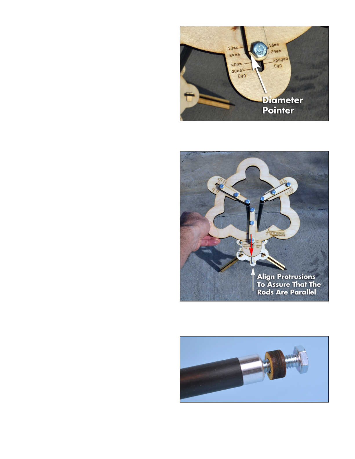
Adjusting the tower for the diameter of the
rocket:
Loosenthethumbscrewsonthesupportarms,sothe
supportarmscanslidealongtheplates.Usingthe
diameterpointerlineonthetopsideofthesupportarm,
slidethesupportarmtothedesiredtubediameter.Once
inposition,tightenthewingnutstolockitintoplace.Do
NOTovertighten,asitcoulddamagethewoodenpieces.
Follow this same procedure for the remaining support
arms.
Aligning the rods:
Oncethediameterisset,andbeforeyouslidetherocket
intothetower,therodsmustbealignedtomakesure
they are all parallel.
First, Slightly loosen the thumb screws on the base
of the three rods!!!
Tilt the tower over to one side. Sight along the top and
bottom base plates. Gently twist the top plate so that the
protruding parts are in line with each other. Tilt the tower
backtotheuprightposition,andre-tightenthethumb
screws holding the rods to the support arms.
Congratulations!You’rereadytolaunchyourrocket.
Note:Becausethetowerissolightweight,onbreezy
days,youshouldstakethetowertotheground.Theholes
in the bottom of the legs can be used as anchor points.
Precautionary notes:
Do not pick up by grabbing all three rods in the middle.
Thiswillcausetheendplatestorotate,andyou’lllose
alignment of the rods. It could also cause damage to the
supportpieces.PickupbyONErodonly.Thetoweris
verylight-weight,weighingonly2lbs6ounces,soyou
can do it.
Disassembly
The rods and the three legs can be disassembled for stor-
age and to make transportation easier.
Remove the legs by pulling the leg lock-down keys out of
theslotsinthelegs.Youcantietheleglock-downkeys
together using piece of wire which is inserted into the hole
on the parts.
Remove the rods by removing the screws at both ends.
To keep from losing the screws and the wooden spacer
rings,putthespacerringbackontothescrew,andthen
thread the screws into the ends of the graphite rods.
Table of contents