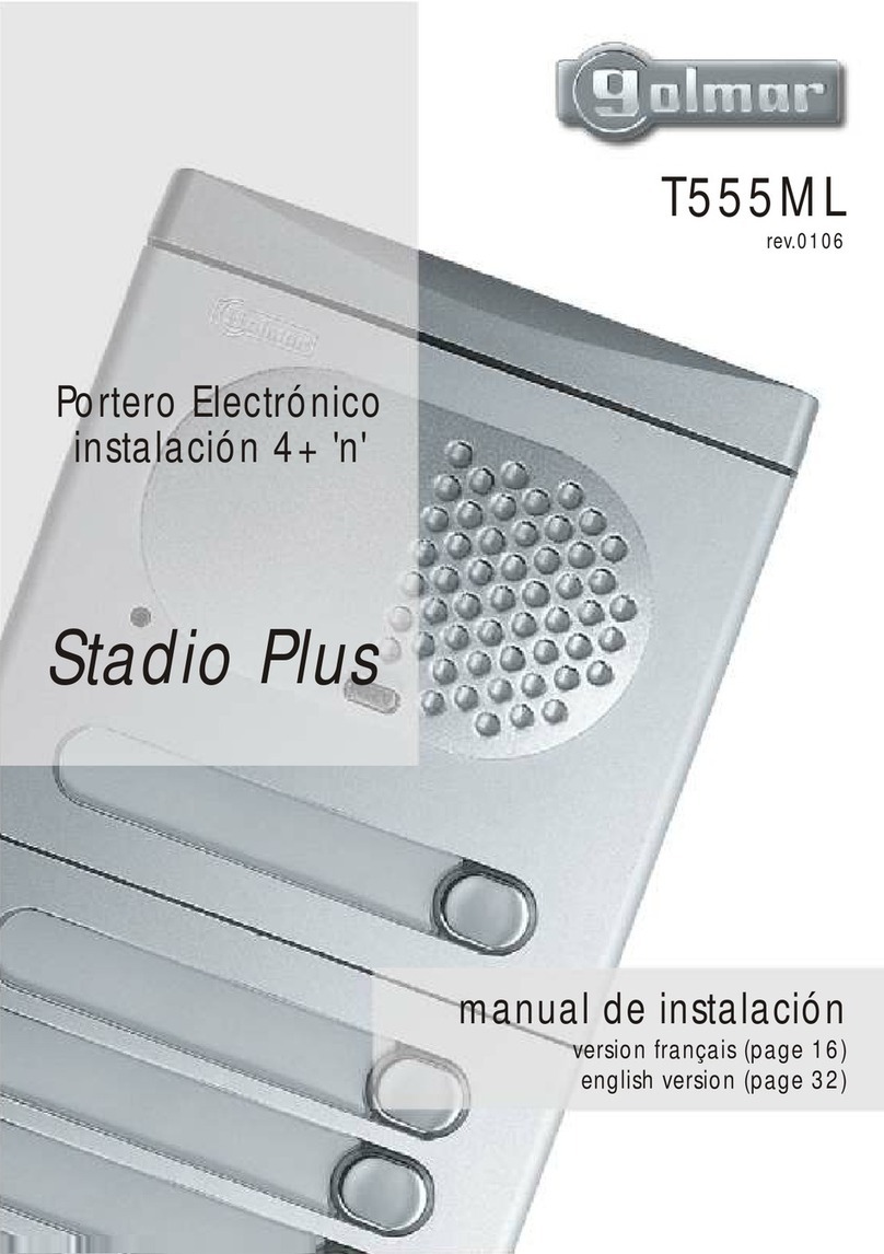
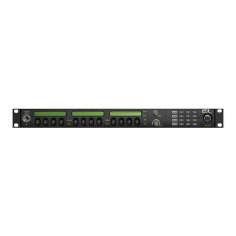
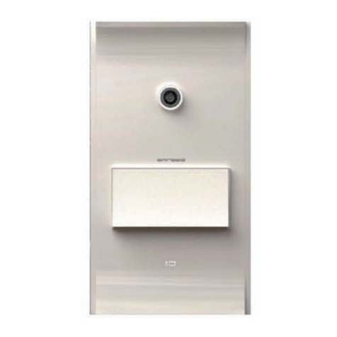
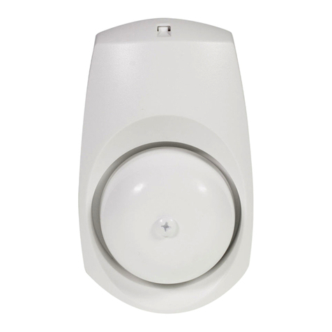
Aerotech Wireless Clear Call User manual

Clear Call
Wireless Intercom
Installation Manual
A facility needs to be evaluated whether it is suitable for wireless application.
Aerotech Wireless, Inc. is not responsible for any mis-application of this product.
Please read the entire manual before installation.

Warranty
Aerotech Wireless, Inc., warrants, for twenty- four (24) months from the date of invoice,
the Clear Call™ systems and other related systems and e uipment manufactured by
Aerotech Wireless, Inc., to be free from defects in material and workmanship under
normal use and service for which it was intended provided it has been properly
installed and operated.
Aerotech Wireless, Inc.’s obligations under this warranty shall be limited to the repair or
exchange of any part of parts manufactured by Aerotech Wireless, Inc. Defective products
must be returned to Aerotech Wireless, Inc., freight prepaid by purchaser, within the warranty
period. Items returned will be repaired or replaced, at Aerotech Wireless, Inc.’s option, upon
an examination of the product by Aerotech Wireless, Inc., which discloses, to the satisfaction
of Aerotech Wireless, Inc., that the item is defective. Aerotech Wireless, Inc. will return the
warranted item freight prepaid.
The products manufactured by Aerotech Wireless, Inc., are not warranted to meet the specific
re uirements, if any, of safety codes of any particular state, municipality, or other jurisdiction,
and neither Aerotech Wireless, Inc., assume any risk or liability whatsoever resulting from the
use thereof, whether used singly or in combination with other machines or apparatus.
Any products and parts not manufactured by Aerotech Wireless, Inc., will carry only the
warranty, if any, of the manufacturer. This warranty shall not apply to any products or parts
thereof which have been repaired or altered, without Aerotech Wireless, Inc.’s written
consent, outside of Aerotech Wireless, Inc.’s production facility, or altered in any way so as, in
the judgment of Aerotech Wireless, Inc., to affect adversely the stability or reliability of the
product(s) or has been subject to misuse, negligence, or accident, or has not been operated
in accordance with Aerotech Wireless, Inc.’s instructions or has been operated under
conditions more severe than, or otherwise exceeding, those set forth in the specifications for
such product(s). Aerotech Wireless, Inc., shall not be liable for any loss or damage
whatsoever resulting, directly or indirectly, from the use or loss of use of the product(s).
Without limiting the foregoing, this exclusion from liability embraces a purchaser’s expenses
for downtime or for making up downtime, damages for which the purchaser may be liable to
other persons, damages to property, and injury to or death of any persons.
Aerotech Wireless, Inc., neither assumes nor authorizes any person to assume for them any
other liability in connection with the sale or use of the products of Aerotech Wireless, Inc.
This limited warranty extends only to wholesale customers who buy directly through Aerotech
Wireless, Inc.’s normal distribution channels.
Consumers must in uire from their selling dealer as to the nature and extent of that dealer’s
warranty, if any. This warranty is expressly in lieu of all other warranties expressed or implied
including the warranties of merchantability and fitness for use. This warranty shall not apply to
products or any part thereof which have been subject to accident, negligence, alteration,
abuse, or misuse or if damage was due to improper installation or use of improper power
source, or if damage was caused by fire, flood, lightning, electrical power surge, explosion,
wind storm, hail, aircraft or vehicles, vandalism, riot or civil commotion, or acts of God.
-1-

Table of Contents:
Warranty …....................................................................... age 1
Installation Guidelines ….................................................. age 3
Outdoor Unit Setup …....................................................... age 5
Indoor Installation …......................................................... age 7
Indoor Unit Setup ….......................................................... age 9
Trouble Shooting ….......................................................... age 11
-2-

Installation Guidelines:
Antenna installation:
1) Make sure Outdoor Unit antenna in installed min 8 feet above ground.
(This ensures good range and avoids antenna vandalism)
2) Ensure antenna is not installed against any metallic surface. To avoid
reducing radio range install antenna at least 24” away from steel post
or building structure (Figure 1).
3) After wire installation, ensure enclosure knockouts are properly
sealed– to avoid water intrusion.
Outdoor Unit installation:
1) Open enclosure - using key.
2) Disconnect 6-inch antenna extension cable inside enclosure.
(Figure 2)
3) Remove the front door by removing the two hinge screws. (Figure
2)
4) Remove knockouts (back or bottom – as necessary) and fish wires
through knockout.
5) Mount back enclosure using mounting holes.
6) Re-install front door using two hinge screws.
7) Re-connect 6-inch antenna extension cable inside enclosure.
8) Follow wiring and setup instructions for Outdoor Unit.
9) Run 6-foot antenna extension cable as necessary and mount
antenna.
10) Screw 6-foot antenna extension cable on back of enclosure and
run
cable as necessary to antenna location.
11) Mount antenna and ensure that it is hand tight.
-3-

Figure 1
Figure 2
-4-

Outdoor Unit Programing:
Note: Step numbers correspond to numbers in figure 3.
1) Install Power Transformer provided with system (avoid sharing
the power transformers provided, to power other devices)
2) Adjust Speaker Volume
3) Select Radio Channel (0 9)
4) Select Strike Times for Relay 1 and Relay 2
5) Select Access Point Number (1-9 for Outdoor Unit)
6) To verify radio signal quality, turn on Test Switch:
- Ensure remote Indoor unit is powered & turned ON
- Set the radio channel of remote Indoor unit to same channel as
Outdoor unit being tested
- Turn OFF TEST switch on remote Indoor unit
- Start testing: observe Quality LED bar and position unit to
obtain
best signal quality
- Turn OFF TEST switch after testing
7) Connect screw terminal to Ground Rod using 12 AWG wire – to
ensure surge protection
8) Connect dry contact Inputs
- “Exit” Switch (RTE)
- “Call” Switch for vehicle auto call feature
9) Connect Relay 1 and Relay 2 Terminals
-5-

Figure 3
-6-

Indoor Installation:
Indoor Unit installation:
1) Open enclosure by removing 4 screws.
2) Disconnect 6-inch antenna extension cable inside enclosure.
(Figure 3)
3) Remove the front door.
4) Remove knockouts (back or bottom – as necessary) and fish wires
through knockout.
5) Mount back enclosure using mounting holes.
6) Re-connect 6-inch antenna extension cable inside enclosure.
7) Follow wiring and setup instructions for Outdoor Unit.
8) Re-install front door using 4 screws.
9) Install antenna on top of enclosure and ensure that it is hand tight.
-7-

Figure 4
-8-

Indoor Unit Setup:
Note: Step numbers correspond to numbers in figure 5.
1) Install Power Transformer provided with system (avoid sharing
the
power transformers provided, to power other devices)
2) Adjust Speaker Volume
3) Select Radio Channel (0 9)
4) Connect screw terminal to Ground Rod using 12 AWG wire – to
ensure surge protection
-9-

Figure 5
-10-

Trouble Shooting:
Unable to all remote unit (from Indoor or Outdoor inter om):
1) Ensure power is applied (check power input voltage using volt
meter – needs to be 12V – 16V AC or DC.
2) Ensure TEST Switch in in OFF position in the “RADIO SIGNAL
TEST” section of the board.
Note: Intercom needs to be in Normal operation mode to call.
3) Ensure the RADIO CHANNEL positions on the “Outdoor” and
“Indoor” units match
4) Ensure all “Outdoor” Intercom units have their “ACCESS T”
rotary switch set between 1-9 (not 0)
5) Check if the remote unit (Outdoor or Indoor) that you are calling
is in “Idle” mode and not in “Voice Communication” mode (off-
hook).
- ush the “Call” switch on remote unit to ensure it hangs up
(see figure 6).
Note: If remote unit is able to call other units, then it is in “Idle”
mode.
6) Ensure that the antennas on all units are securely installed (hand
tighten) (see figure 7).
7) Ensure any antenna extension cables are securely installed (hand
tighten)
8) Keep the Intercom units away from any other radio devices, such
as handheld radios-to avoid radio interference.
9) If all above is verified, and still unable to call, then perform a
“Range Test” (see instructions below).
Poor audio sound:
1) If audio has static (or other) noise, ensure the front door of the
units are shut before initiating audio communication
2) If audio has feedback (static heard after speaking on local unit),
lower the volume of the remote unit. This will reduce the sound
echo feedback on the remote unit.
-11-

Figure 6
Figure 7
-12-

“Range Testing” Procedure:
1) osition the pair of intercom units in their respective locations
(as close to their final location as possible)
2) ower ON only a single pair of units (one Indoor and one Outdoor
Intercom units) to perform a “Range Test”. All other Intercom
units need to be turned OFF.
3) Ensure the “Outdoor” unit's antenna is min 8 feet above ground.
4) Flip the “TEST Switch” to ON position in the “RADIO SIGNAL
TEST” section of the board on “Outdoor” unit. The “QUALITY”
LED bar graph as well as the “LEVEL” and “HISTORY” LEDs
will light up. The unit will now automatically initiate
communication with the remote unit and provide the quality of the
radio of the radio link between them. rimarily focus on the
“QUALITY” LED bar graph for assessing the radio link (see
figure 8).
5) If the “QUALITY” LED bar graph has more than 2 bars on,then
the link is GOOD (Skip next step)
6) If the LED bar has less than 2 bars, then do the following to
improve the range:
- Move the “Outdoor” intercom unit (or their antenna using
extensions) to different location
and observe the “QUALITY” LED bar graph again to see if the
range has improved.
- Move the “Indoor” Intercom unit (or their antenna using
extensions) to different location and observe the “QUALITY”
LED bar graph again to see if the range has improved.
Note: Repeat the steps above until the ideal location for antennas
are determined.
7) If the building walls are metal reinforced and the “Range Test”
results are poor, then the antenna of the “Indoor” Intercom unit
may need to be mounted near a window – using antenna extension
cable(s). For worst-case applications, the antenna may need to be
mounted outside of the building (on outer wall) (see Figure 9).
Again, utilize the “Range Test” feature to determine optimal
position for antenna.
8) In applications where extreme range is required , high gain
antenna my be utilized (see Figure 10).
-13-

Figure 8
Figure 9
Figure 10
-14-

Aerotechwireless.com
Table of contents
