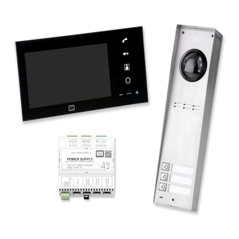
ACO FAM-P Installation instructions

-2-
TABLE OF CONTENTS
I. GENERAL INFORMATION ........................................................................................................................................... 4
II. TECHNICAL PARAMETERS........................................................................................................................................ 5
III. USING THE PANEL...................................................................................................................................................... 6
IV. ADDITIONAL MODULES......................................................................................................................................... 10
V. MOUNTING AND CONNECTING THE PANEL....................................................................................................... 11
1- ASSEMBLY.......................................................................................................................................................................................................11
2 - CONNECTING THE PANEL.........................................................................................................................................................................12
3- WIRING DIAGRAMS FOR SINGLE PANEL INSTALLATION ...............................................................................................................16
VI. INSTALLATION AND CONNECTION OF RECEIVERS........................................................................................ 21
VII. VOLUME LEVEL ADJUSTMENT........................................................................................................................... 21
VIII. OPERATION OF MORE THAN ONE PANEL....................................................................................................... 21
1 - INSTALLATION OF THE SLAVE PANEL .................................................................................................................................................23
2 - PROGRAMMING THE SLAVE PANEL......................................................................................................................................................23
3 - WIRING DIAGRAM OF INSTALLATION WITH MULTIPLE PANELS...............................................................................................24
IX. DOORMAN FUNCTION ............................................................................................................................................ 31
X. PANEL PROGRAMMING ........................................................................................................................................... 31
0 - SERVICE DOOR OPENING..........................................................................................................................................................................32
1 - ACCESS CODE CHANGE (RESIDENT, ADMINISTRATOR) .................................................................................................................32
Modification of user’s access code......................................................................................................................................................................32
Modification of administrator’s initial access code ............................................................................................................................................33
2 - SETTING E-LOCK OPENING TIME...........................................................................................................................................................33
3 - SETTING THE NUMBER OF RINGTONES, PERMISSION TO CALL APARTMENT .......................................................................33
4 - TURNING ON - OFF THE DOOR OPENING SIGNAL IN THE APARTMENT ....................................................................................33
5 - SETTING ONE OF FOUR RINGTONES .....................................................................................................................................................34
6 - TEST ACTIVATION OF THE E-LOCK AND CALLING THE RECEIVER FROM APARTMENT...................................................34
7 - CHANGING THE INSTALLER’S PASSWORD..........................................................................................................................................34
8 - SETTING THE DIRECT CALL BUTTON ADDRESS................................................................................................................................35
9 - ENTERING NEW ACCESS CODE TABLE.................................................................................................................................................35
XI. PANEL PROGRAMMING VIA A PC........................................................................................................................ 35
XII. INSTALLING THE BUTTON FOR ADDITIONAL INPUT.................................................................................... 39
XIII. RESTORING FACTORY SETTINGS OF THE PANEL......................................................................................... 39
XIV. FACTORY SETTINGS............................................................................................................................................. 39
XV. MAINTAINING CLEANLINESS.............................................................................................................................. 40
XVI. SAFETY RULES FOR INSTALLATION AND USE.............................................................................................. 40
XVII. RULES FOR STORING WASTE ELECTRICAL EQUIPMENT .......................................................................... 40
XVIII. TROUBLESHOOTING.......................................................................................................................................... 41
The panel must not be installed without reading the instructions below.

-3-
Hint:
Brief description of programs in the service menu (installer mode), which is available in models
with a numeric keypad:
Programme No. Function
0. Service door opening
1. Change the opening code (resident, administrator)
2. Setting E-lock reset time
3. Setting the number of ringtones, permission to call apartment
4. Turning the door opening signal off - on
5. Setting one of four ringtones
6. Test activation of the E-lock and uniphone call from apartment
7. Changing the installer’s password
8. Setting the direct call button address
9. Entering a new access code table

-4-
I. GENERAL INFORMATION
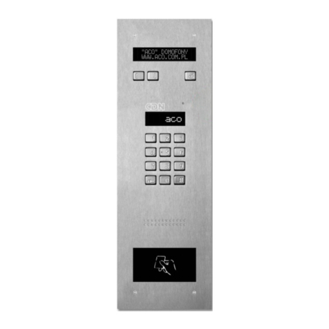
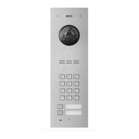
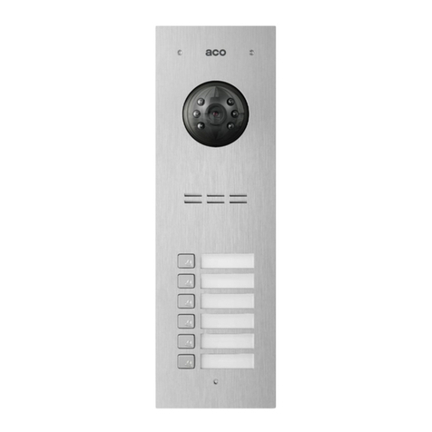
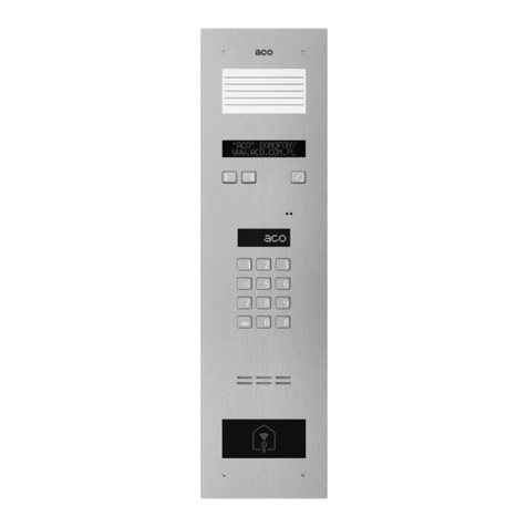
Familio P and PV are a series of digital panels with an option of dialling the apartment number from
the numeric keypad and/or direct dialling buttons and with access control function (opening the
entrance door with a code and/or proximity key fob). Depending on the version, the panels can
feature up to two direct dialling buttons with a backlit space for name and/or an illuminated numeric
keypad as well as with an RFID reader (ACC) in the Unique 125Hzstandard embedded in the bottom
description field. The panel are also capable to interface with different external devices.
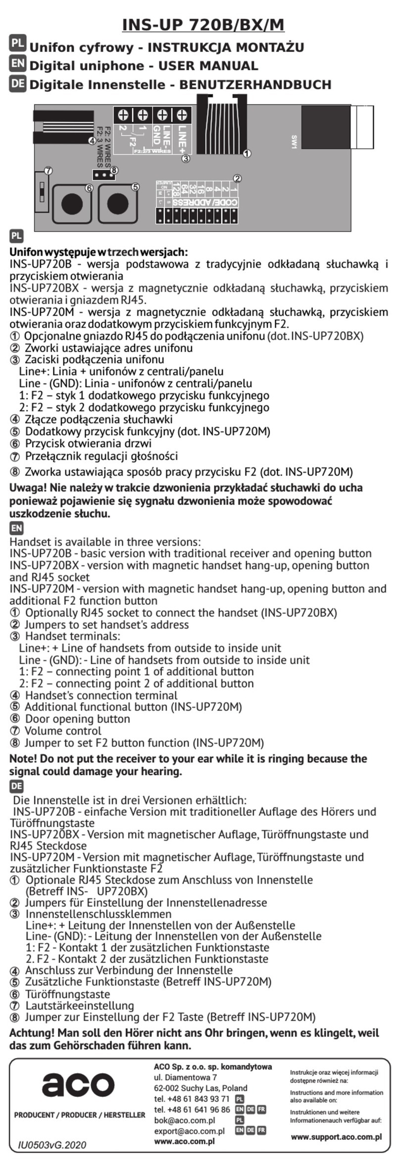
The devices work in a two-wire installation for passive audio systems (such as INS-UP720BX), in
four-wire installations for active audio systems (such as UP800) and in installations based on UTP
cable for Video version (such asINS-MP7). It is recommended to use UTP cat. 5e/6. The Familio
series will work with all P system panels, namely INSPIRO, CDNP and with all P system receivers.
The panels can work in mixed audio and video systems (provided that the whole system is supplied
with DC).
Panel front is made of stainless steel, which provides effective protection against devastation and
weather conditions. The built-in PV series colour camera of is adjustable in horizontal and vertical
plane, and with IR illumination the images can be viewed even in darkness.
Familio panels are easy to operate, functional, their installation is simple and feature configuration
options and a lot of parameters can be changed in the settings. Certain settings can be changed
directly from the service menu available for panels with numeric keypad, while all settings are
available via FAM_P computer program (PC/Windows). Adding (deleting / archiving / transferring
between panels) proximity fobs can be done using the ACC_v3 software (PC/Windows). In order to
connect the panel to a PC, a special CDN-USB cable should be purchased separately (cable
suitable for all ACO products). The software mentioned is available for free and can be downloaded
from www.support.aco.com.pl
Familio series digital door entry units be expanded into complex multi-entry systems that combine
many panels, for instance: closed housing estates, gate house, main gate, building entrances etc.
In practice this makes it possible to call an apartment both at the entrance to the site as well as the
entrance to a building or staircase. Their other advantage is the possibility to individually program
the ringing parameters for each apartment, by choosing one of the four available signals and signal
repetition in the ringing cycle. With two pre-programmed additional numbers it is possible to call one
uniphone using three different numbers (each with different ringing settings), such as in a tenement
house where one uniphone is used by several apartments on the same floor. The panels can also
control an additional door using tenant’s access codes (MINI I/O module or CDN-I/O). For detailed
information on the operation and capabilities of the panels refer to this manual.
The advantages of FAM-P and FAM-PV series panels include
(depending on version):
White backlight
Settings storage and programming via a PC (optional CDN-USB cable to be purchased
separately),
Easy to use - adapted for people with hearing or vision impairment (optional Braille keypad),
Two-wire installation for passive audio receivers
No eavesdropping on calls from other receivers,
Individual front door opening code for each unit,

-5-
Individual code controlling an additional output (such as second gate) for each apartment,
Delayed and further door opening in a multi-panel system,
Door opening with administrator’s code,
Emergency door opening in case of line failure,
Individually set call ringtones for apartments,
Individually set number of rings for apartments,
Individually adjustable ringing volume levels for apartments,
Supports up to 150 physical addresses, including two additional numbers (only version with
numeric keypad - "ZS")
Direct call buttons
Programmed receiver test modes,
Option to set any code table - easier service,
Service inspection of uniphone by the installer during installation,
Service activation of E-lock during its adjustment or installation,
Option of door opening or direct call with additional external push button - built-in INPUT,
Modern, stainless steel panel front,
Resistance to corrosion and vandalism,
Flush or surface mounting
Backlit tenants’ list,
Option of combining a number of panels in one system,
Interface with a number of additional external modules,
Doorman function
Panels can be customised to individual requirements,
Adjustable camera position in each direction (FAM-PV panels)
Option of image viewing in darkness - infrared illumination (FAM-PV panels)
Support for proximity key fobs (version with built-in ACC): up to 192 key fobs
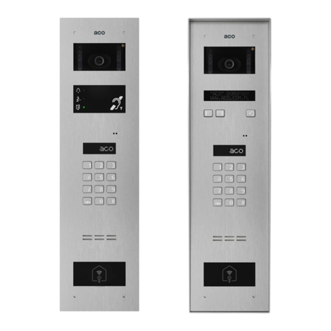
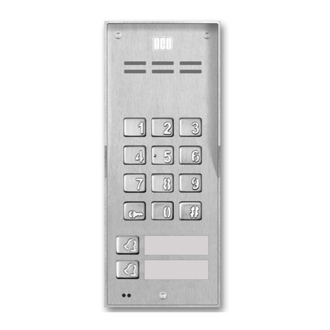
FAM-P (audio) series includes versions of panels that are both surface mounted (NT) and flush
mounted (PT), with code lock (ZS), with direct dial buttons (xNP, where x means the number of
buttons) and with proximity key fob reader (ACC).
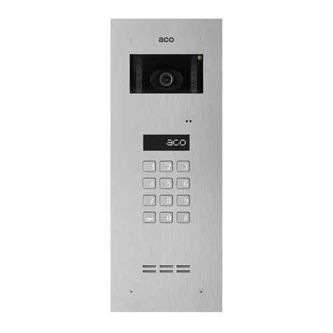
The FAM-PV (video) series panels that are flush mounted (PT), surface mounted using a dedicated
frame (PNT2-FAM-PRO/PV), with code lock (ZS), with direct dial buttons (xNP, where x means the
number of buttons) and with proximity key fob reader (ACC).
White backlit, stainless steel keypad featuring a modern design ensures trouble-free
operation for many years. Keypads like this are widely used by telecoms in modern
equipment, easily accessible to the public particularly vulnerable to devastation.
II. TECHNICAL PARAMETERS
1. FAM-P Panels:
Power supply: 11.5V AC ±5% or 15V DC (13.5 - 15.5V DC)
Power consumption in standby mode: ~1.3W
Current consumption: max. 130mA, without E-lock
Support for proximity key fobs (ACC version): max. 192 key fobs
Permitted load of E-lock output: 1A
Front: stainless steel; mounted with 3mm Allen (hexagon) screws

-6-
Required space for flush-mounted panel: 197 x 90 mm (H/W/D)
Hole dimension for flush-mounted box: 180 x 74 x 33 mm (H/W/D) with add-on 180 x 74 x
50 mm module
Space required for surface panel mounting: 177 x 70 mm (H/W)
Space required for flush-mounted panel with surface-mount adapter (PNT2-FAM-P): 199
x 92.4 mm (H/W)
Hole dimension for flush-mounted adapter (FAM-R-S-NT/PT): 180.5 x 77 x 25 mm
(H/W/D)
2. FAM-PV panels:
Power supply: 15V DC (13.5 - 15.5V DC)
Power consumption in standby mode: ~2.8W
Current consumption: max. 260mA, without E-lock
Support for proximity key fobs (ACC version): max. 192 key fobs
Permitted load of E-lock output: 1A
Front: stainless steel; mounted with 3mm Allen (hexagon) screws
Required space for flush-mounted panel: 286 x 90 mm
Hole dimension for flush-mounted box: plastic box 269 x 73 x 32mm
Required space for surface-mounted panel with flush-mounted adapter (PNT2-FAM-
PRO/PV): 288.4 x 92.4 mm (H/W)
Hole dimension for flush-mounted adapter (FAM-R-M-NT/PT): 270.5 x 77 x 36 mm
(H/W/D)
III. USING THE PANEL
To call an apartment, press the appropriate ringer button (direct call button) - the receiver in the
apartment being called will start ringing. For the video version, a camera image will also appear in
the monitor during the call (by default, captured at the panel from which the call was made). Direct
call buttons are by default assigned to addresses from the bottom: address 1 (bottom button) and
successively up to address 6 (top button). It is also possible (after changing the settings via the PC
program or directly on the panel numeric keypad: function "change of factory settings" - page 22) to
call apartments by selecting apartment number using the keypad buttons, in a conventional manner
as in the case of CDNP panels orINSPIRO panels (FAM-P/PV-ZS panels with code lock only, without
direct call buttons have this option set by default). In this case, the receiver in the apartment will start
ringing after approx. 3 seconds.
First, the panel sends ringing tones (two ringtones by default, the number of ringtones can be
changed in program 3 of the service menu or via the PC program) and sets itself to stand by waiting
for the handset to be picked up. If the handset is not picked up within 20s, another single signal is
sent and the panel continues waiting for 20s. If the call is not answered within some 40s, the ringtone
is automatically ended and the panel returns to standby mode. Calling an apartment can always be
cancelled with the “#” key or any direct call key.
If the call is answered during the waiting time (handset is picked up), the call will be established. Now
conversation is possible and the entry door and/or a second gate (connected to the panel from which
the call is in progress)can be opened. The call may last up to 2 minutes, unless the call is terminated
earlier (handset is hanged up) or the call is interrupted by pressing "#" (the call time can shortened
via the PC program).

-7-
The panel detects a line short circuit - signalled by blinking keypad backlight. During this time, E-lock
can be activated by pressing any button and building can be entered. When the correct state of the
line is detected (when short circuit ceases), the panel is automatically restored to normal operation.
An additional output module with relay can beconnected to the panel, for instance to controla second
gate. For Familio P and PV panels a special MINI I/O module is dedicated to be mounted directly in
the panel. It features NO, NC relay output. It can be used to control lights in the hallway or open an
additional gate, etc. Alternatively, the CDN-I/O module with dual relay outputs can be used.
All FAM-P and FAM-PV panels feature an output for direct connection of an E-lock, also reversible
E-lock. In order to connect a device other than an electric door strike, a relay needs to be connected
in its place as per the diagram on page 15 or the CDN-PK relay module needs to be used.
When opening the door, the panel generates an audible signal (information for persons with vision
impairment) and the keypad backlight blinks (information for persons with hearing impairment). The
opening time (by default 4 seconds) can be changed via the PC program or from the service menu
- program 2.
The front door can be opened in the following manner:
With the push button on receiver in the apartment
The door will open upon pressing the opening button ("key") on the receiver during an active call.
During one call (conversation) it is possible to open the door three times, after which the call is
automatically terminated.
It is possible to open without having to connect with the apartment. In this case, on classic uniphones
the handset must be picked up and the open button pressed three times, on active receivers (INS-
UP720MR, UP800/MP800, INS-MPx) the open button must be pressed once (without having to pick
up the receiver).
Opening additional door with the uniphone F2 button
Opening (activation of the relay in the optional I/O module) is possible by pressing the F2 button
on the receiver during an active connection. To open a second door without connecting with an
apartment, connect the wires from the second door directly to the receiver (only selected receiver
models, for instance: INS-UP720M / INS-UP720MR, UP800(G2), MP800G2). Default setting for
the relay is 2 seconds (can be changed using the software). It is possible to activate the relay of
an I/O module (CDN-I/O only) without receiver in the apartment picked up - for this panel settings
have to be changed (section on I/O module) using the PC software (the opening method is
identical with and replaces the opening method for doors without receiver in the apartment picked
up described above).
Opening with the proximity key fob (ACC)
To open the door place the key fob to the lowest description window with the panel in the standby
mode. In case the key fob is not registered, the panel generates fast beeps. In order to add
proximity key fobs use the free ACC_v3 software, version v3.5 or higher, and connect the panel
to the PC using the optional CDN-USB cable (to be purchased separately). The software is
available at www.support.aco.com.pl
Opening with access code (default setting, except Fam-P-ZS and Fam-PV-ZS)
In order to open the door, use one of the two codes by entering it directly on the keypad. The default
codes are:
- for the bottom key: 1111
- for the top button: 2222
-8-
Note! It is recommended to change the codes upon installation of the panel is complete.
The code can be changed by the user as follows: Enter the current code, then within 1.5 second
press and hold the "key" button (for approximately 4s), until the panel emits up-modulated sound.
Then enter a new four-digit code, which the panel will confirm with a sound.
The panel has a function to notify residents when the code is used (door opening signal). When the
correct code is entered, a short triple beep sounds in the receiver to which the code is assigned (this
function can be deactivated using the software or directly from the service menu - program 4).
Opening additional door with a code or a key fob (default setting)
Opening (activation of the relay in the optional I/O module) directly from the panel is possible
when the opening code is preceded by pressing the key twice. When using a proximity key fob,
press the key button once before applying the key fob.
Opening with access code (optional, default setting for Fam-P-ZS and Fam-PV-ZS)
If the panel is configured to handle calls from numeric keypad (as in the case of CDNP or INSPIRO
panels), to open with the user code, select the apartment number on the keypad, confirm it with the
"key" button and select the four-digit entry code assigned to the apartment (physical address of the
receiver). The opening codes are separate for each apartment and correspond to the code table,
which can be changed/entered using service program #9.
By default, the code table is only added to panels FAM-P-ZS and FAM-PV-ZS. For other versions of
the panel, use the code table that is used in the panel/master panel or generate it using the "ACO
Code Generator" available at www.aco.com.pl in the user zone or at
www.aco.com.pl/aco_generator/
The website can also be used to prepare name tags for residents, containing the apartment number,
the opening code and instructions for its use. A name tag may include a logo and one line of text for
company name and phone number etc..
If the code table number is "9999", opening with the user code is disabled.
Opening with administrator’s access code (optional setting, default setting for Fam-P-ZS
and Fam-PV-ZS)
If the panel is configured for dialling from the numeric keypad (conventional method, as in case of
CDNP or INSPIRO panels), opening with the master code is possible by selecting the "key" button
on the panel keypad, and then the 6-digit master code (the code can be shortened to the first 4
digits - setting via the PC program). This code is used by persons such as technicians, postmen,
housekeepers, etc. Two such codes can be entered in the panel.
Service opening - using program 0
Service opening is possible by entering the service programming function for panels with numeric
keypad and selecting "0" on the keypad. When door opening is activated, the programming function
is automatically exited.
Opening with any keypad button in case of line failure
In case of uniphone line short-circuit, which makes it impossible to call any apartment, pressing any
key will open the door (short-circuit of uniphone line is signalled by flashing keypad backlight).

-9-
Opening with additional push button
The panel features an additional INPUT, which is configured by default as additional opening - when
shorted to ground it activates door opening. Such opening while the call is pending completes the
procedure of calling the apartment.
This input can be connected to any NO button such as INS-OB, code lock, card access reader,
motion detector etc. The input is protected against a permanent circuit short-circuit (short circuit
triggers it’s disconnection from the system until released).
Further door opening
The slave panel features the so called a further door opening function. If the master panel opens the
door and terminates the call or opens the door with an access code or proximity key fob, the waiting
time is automatically activated in the next slave panel. During this time, pressing any button (except
"#") activates door opening. This option is enabled only in those slave panels through where the call
originated or which must me used (passed) to reach the apartment assigned to the access code or
proximity key fob used. Standby mode can be cancelled with the "#" button. If the parameter "Open
after delay" is activated, after the pre-set delay time has passed the door will be opened automatically
without pressing any key. The wait time is set in each slave panel. The further door opening pulse
must be enabled on the master panels. The function is disabled in the panels' default settings and
can be enabled using the software.
Opening using the input from the additional module
The panel can be used for opening via an additional module, such as an I/O module. The module is
connected to the EXTMOD socket on the panel board and configured via the PC program.
Automatic opening when calling an additional number
If the "Auto door opener" function is enabled (for additional number only) and the handset is not hung
up (picked up), door openingwill be activated automatically after thefirst ringing signal. If the handset
was hung up during the first ringing tone, the panel works normally - the handset can be picked up
and communication is possible. The automatic opening function is commonly used in commercial
buildings
- letting people in is done by simply lifting the handset; after business hours the handset is hung up
and the door entry unit works normally. For this purpose, the recommended receiver model is INS-
UP720B/XM. For certain active receivers (for example UP800/MP800/INS-MP7) it is possible to
activate the auto-opening function independently.
Additional numbers.
Two additional supported numbers can be added for the ringing operation mode using numeric
keypad buttons. These can be any number in the range of 1-999 (disabled by default), to which
physical addresses of receivers can be assigned. Additional numbers can assigned to the same
receiver so that it can be called using three different numbers (for instance two additional numbers
and one primary number). Each such additional number may be configured with different ringing
parameters (ringtone and number of signals).
If the primary numbers and additional numbers overlap, the latter have priority and calling in these
cases is always made according to their settings. The access codes are the codes in the table,
corresponding to the physical address of the receiver.

-10-
IV. ADDITIONAL MODULES
MINI I/O module (additional output)
Expansion module to control a second gate or other
home automation and external devices. Mounted directly
on the Familio P/PV panel. It features a relay output. The
module can be used for instance to control the opening
of an additional or main gate, to operate the staircase
lighting, to control the barrier, etc. The module
parameters are set via the PC program for changing
Familio panel settings (FAM_P). More information at
www.aco.com.pl Description of module configuration -
chapter XI.
CDN-U signalling module with opening function
This module can be used to connect additional devices signalling
ringing in the apartment, for instance additional bells, light bulbs,
signallers etc. for persons with disabilities. The module also
enables automatic door opening without picking up the handset.
The module can operate independently (built-in sounder) and in
parallel with the receiver.
CDN-Pk module
Relay module, with NO and NC contacts, cooperating with all CDN,
INSPIRO, FAMILIO panels. It enables connection to the ELOCK
output of an electromagnetic jumper, gate control, barrier or E-lock
with specific requirements, etc.
PLEASE NOTE! Connect all additional modules to EXTMOD output, including CDN-USB as
shown in the figure on the left.

-11-
V. MOUNTING AND CONNECTING THE PANEL
ASSEMBLY
The panel should be assembled so as to minimise the impact of adverse weather conditions, in
particular water.
Allen key 3
Allen key 3
Allen key 3

-12-
Install theflush-mounted backbox (orflush-mounted adapted) in the appropriate wall opening,
using holes 5and rawlplugs (or screws) as well as gypsum; make sure that the back side of the box
flange A is flush with the mounting surface. When mounting on a steel pole (similar structure with a
maximum wall thickness of 32 mm), use an additional set of gaskets and screws 3 - available as an
option. Run the wires through hole 1in the box base (cut out the cap if larger hole is needed). Use
additional holes 4for makeshift installation with nails etc. when mounting the unit in soft materials
such as polystyrene. Holes 4also make installation easier when using mounting foam. The cover
cap 2should be cut out in order to install the add-on module in its place. For the best possible
tightness, cut out only those holes that are necessary to install the panel. Check the condition of the
gasket on box B. Cracks, deformations and soiling of the gasket may lead to loss of tightness.
Install the flush-mounted back box in a suitable place, using holes 6 holes and rawlplugs or
suitable screws. Lead the wires through hole 7in the box base.
Then screw evenly all screws of the housing to the back box using a 3mm Allen wrench.
Make sure that the camera is installed at the desired height. Typically that height is 1.60 m
from the ground. For optimal field of view of the camera, verify the installation location and position
of the panel by trial and error. Avoid locations where the camera lens may be exposed to direct,
perpendicular, light (from the sun, street lamps, etc.).
2 - CONNECTING THE PANEL
All connections in the installation must be soldered!
The following wires need to arranged to the unit:
- 2 wires x 1mm2- power supply from the Audio system transformer or power supply from the DC
power supply (15VDC) for the Audio/Video system
1 wire in yellow green insulation - to connect the housing's grounding (PE)
2 wires x 0.75mm2- for E-lock,
- 2 wires x 0.5 mm of door entrycable to connect receivers - for Audio systems with passive receivers
(such as INS-UP / INS-UP720B/X/M), or
- 4 wires x 0.5 mm of door entry cable to connect receivers - for Audio systems with active receivers
(such as INS-UP720MR / UP800), or
- 1 x UTP cable (min. cat 5e) - for video systems
Note! All RJ45 plugs on UTP must be crimped in T568B standard.
If cross-sections are smaller and connections that are too long, voltage drops may occur, causing
the panel to malfunction. To extend the length of cables, their cross-section must be increased.
Insufficient power supply, too small cable cross-section and too long connections (voltage drops)
may cause device operation disturbances (such as audio channel disturbances: buzzing or reset
system trip and device restarting, especially when opening the E-lock).
Note! Mixing passive receivers with active receivers (including monitors) is not recommended, as
this may cause the entire system to malfunction.
Important! Use a DC power supply (+15VDC) that has terminals for PE conductor connection. This
eliminates interference (buzzing) in the audio channel, especially in the hands-free receivers, and
ensures trouble-free operation of the entire system.

-13-
If the power supply has no PE connector, the MOD-PE-GND module can be used, available from
Aco, to connect the PE conductor to the intercom system.
Maximum lengths of signal cables (of the line or bus).
The cross section (resistance) of the bus for digital transmission and audio track (LINE terminals)
has a significant impact on the maximum bus length for both Audio and Video systems. For typical
cable cross sections (0.5mm) the maximum distance is 300 m.
This distance increases with increasing wire cross section:
- with 1 mm2wire the distance can be increased to 400 m
- with 1,5 mm2wire the distance can be increased to 600 m
- with 2,5 mm2wire the distance can be increased to 1000 m
Use CDNV-RJ45 module to increase the cross-section of the above mentioned cables (UTP) in the
video system. When necessary, the video signal should also be amplified with the CDNVRAU-DIN
splitter, using the amplified output.
PLEASE NOTE! For proper operation and to ensure safety of
use, connect the panel in its installation point to earth by
connecting the grounding terminal (see picture) on the panel
with a suitable protective installation (PE).
Panel power connection:
Transformer - TR 11.5V AC DC power supply - 15V DC

-14-
1. FAM-P panels only:
11.5V AC supply voltage is connected to the POWER (AC/AC) terminals, while if 15V DC power
supply is used, the supply voltage is connected to the +DC (+ELOCK) and -DC (GND) terminals.
2. FAM-PV panels only:
use only DC supply voltage of 15V DC and connect it to the +DC (+ELOCK) and -DC (GND) terminals
of the panel.
Connect the E-lock, no specific polarity to be observed, to "ELOCK" terminals.
Audio panels and passive receivers (without power supply) are wired to apartments using a
two-wire intercom cable, and the uniphone terminals should be connected in parallel and connected
to the “LINE” terminals on the panel. Make sure that the "+" uniphone terminal is properly connected
to "LINE +” on the panel and the "-" uniphone terminal is properly connected to "LINE -” on the panel.
Improper wiring of even one uniphone will cause bad operation of the entire system.
Audio panels and passive receivers (power supply of receivers is necessary) are wired to
apartments using a four-wire intercom cable, where the LINE terminals of uniphones are connected
in parallel and connected to the "LINE" terminals on the panel, and the "+DC"/"-DC (GND)" terminals
of uniphones are also connected in parallel and connected to the "+DC"/"-DC (GND)" terminals on
the panel. Make sure that the "+" uniphone terminal is properly connected to "LINE +” on the panel
and the "-" uniphone terminal is properly connected to "LINE -” on the panel. Improper wiring of even
one uniphone will cause bad operation of the entire system. It is recommended to use UTP cable in
T568B standard and CDNARU-DIN audio splitters. Note! For active audio receivers, DC power
supplies must be used throughout the system (transformers are not permitted). For a greater number
of active receivers, the number and power of power supplies should be selected based on the
number of receivers in the entire system - detailed information can be found in the assembly
instructions for the active receivers used.
In the case of video panels, the wiring between the panel and the monitors (bus) requires UTP
cable in T568B standard (all wires must be used). All RJ-45 plugs must be crimped with the same
wire order. Use video splitters to connect more receivers, and arrange the bus in such a way that the
UTP cable starts from the panel. Connect the wires to the panel terminals as per the diagram and
UTP colours. The bus is then connected to the main input of the first splitter (RJ-45 plug). Then
connect the main output of the splitter to the main input of the next splitter and so on. The monitors
are connected using individual outputs of the splitters. It is recommended to connect the power
supply from the closest panel to the first splitter (the "auxiliary power" jumper is removed in the
splitter). The distance from the slipper with connected power supply to the receiver must not exceed
70m, while using additional power supplies, the total distance between the first panel and the last
monitor can be up to 300m. The installation can also be arranged in such a way that all splitters are
installed in one place and connection are made to each monitor (in this case the maximum distance
from the splitter to the monitor is 70m, unless the power supply is connected directly to the monitor
- then the maximum distance from the panel to each monitor is 300m). All distances are given for
twisted pair UTP cat. 5e. In system with multiple video panel (Master / Slave), panels must also be
connected using UTPs. - for more information, see chapter: VIII. OPERATION OF MORE THAN
ONE PANEL
Note! Before turning the power on, check for possible short circuits between the wires and
make sure that the wires conduct current and are properly connected to RJ45. It is
recommended to use UTP tester for computer networks - remember to test connection
without connected aco devices !

-15-
If the panel is powered from a buffer PSU with a battery, 13.8V voltage is connected to the "+DC"
and "GND" terminals of the panel respectively.
NOTE! The "ELOCK" output is designed for connecting an E-lock only.
If it is necessary to connect another device, connect it using the contacts of a relay (12V coil)
connected to "ELOCK" terminals with an additional 100 - 470µF electrolytic capacitor (depending on
relay type), as per the diagram:
ACO offers off-the-shelf CDN-PK modules, which can also be used.
The panel may also work with reversible E-lock (closed after applying voltage). The same wiring
diagram applies and the activation of this option is done via the PC program and the Z1 jumper must
be installed in the panel (available under the panel terminals). When working with reversible E-locks,
voltage appears on "ELOCK" output depending on transformer or DC power supply used (15VDC) -
use suitable reversible E-lock or MOD-DC-12V module which will supply 12V DC to the reversible
E-lock.
When wiring is completed and verified as correct, turn on the power supply.
After the panel counts down approx. 30 sec (this time is required for setting uniphones working
conditions and is indicated by an audible signal) the sound volume during a call should be adjusted
as per Chapter VII of this manual.
Then screw evenly all screws of the housing to the base using a 3mm Allen wrench.
NOTE! When setting up the panel-receiver connection, unwanted audible signals may occur,
the level of which does not distort the content of the transmitted message, nor does it
significantly impair the comfort of conversation.

-16-
3- WIRING DIAGRAMS FOR SINGLE PANEL INSTALLATION
Audio panel installation with passive receivers should be connected as per the diagram below:
Line
Line
Line
Line

-17-
The installation of audio panels with active receivers should be connected as per the
diagram below:

-18-
The installations of audio panel with additional external camera and monitors should be connected
as per the diagram below:
To monitor or splitter

-19-
Video panel installation with one monitor should be connected as per the diagram
below:
NOTE!
If the system features only one monitor, no video splitter is necessary and the monitor is connected
at the end of the UTP bus leaving the panel. It is then absolutely necessary to connect the monitor
power supply by connecting the bus cable: orange and brown together to "+DC" terminal of the panel
(in this case the maximum distance between the panel and the monitor is 70m). If the additional
power supply is connected directly to the monitor, the distance (between the panel and the monitor)
can be extended to 300m. When using Video splitters with additional power supplies, cable length
may also be extended up to 300m (between the panel and the monitor), assuming that the splitter,
with a power supply connected to it - is within 70m from the monitor.

-20-
Video Panel with several monitors should be connected as per the diagram below:
Rozdzielacz / Splitter
This manual suits for next models
1
Table of contents
Other ACO Intercom System manuals

ACO
ACO acoGO! P User guide

ACO
ACO Familio PRO User manual

ACO
ACO INS-UA720M User manual

ACO
ACO COMO-PRO-POST-A1 Series User manual

ACO
ACO INS-UP 720B User manual

ACO
ACO COMO-PRO-V Series User manual

ACO
ACO MOD-SPK-PRO User manual

ACO
ACO COMO-PRO User manual

ACO
ACO GLASS-IP-7 User guide

ACO
ACO CDNP6ACC User manual

ACO
ACO FAM-P Series User manual

ACO
ACO INSPIRO 4 Series User manual

ACO
ACO CDNP7ACC User manual

ACO
ACO INSPIRO+audio User manual

ACO
ACO INS-UC 720M User manual

ACO
ACO INSPIRO 1 Series User manual

ACO
ACO FAM-PV Series Installation instructions

ACO
ACO CDNP6ACC Installation instructions

ACO
ACO INSPIRO+VIDEO User manual

ACO
ACO CDNP6ACC User manual