Aerotech Automation1 iPC Series User manual

Revision 1.00
Automation1 iPC Intelligent Industrial PC
HARDWAREMANUAL
GLOBALTECHNICALSUPPORT
Go to https://support.aerotech.com/servicedesk/customer/portal/1 for information
and support about your Aerotech, Inc. products. The website supplies software,
product manuals, Help files, training schedules, and PC-to-PC remote technical support.
If necessary, you can complete Product Return (RMA) forms and get information about
repairs and spare or replacement parts. To get help immediately, contact a service office
or your sales representative. Include your customer order number in your email or have
it available before you call.
This manual contains proprietary information and may not be reproduced, disclosed, or
used in whole or in part without the express written permission of Aerotech, Inc.
Product names mentioned herein are used for identification purposes only and may be
trademarks of their respective companies.
Copyright © 2020, Aerotech, Inc., All rights reserved.

Table of Contents
Automation1 iPC Intelligent Industrial PC 1
Table of Contents 3
List of Figures 4
List of Tables 4
EU Declaration of Conformity 5
Agency Approvals 7
Chapter 1: Automation1 iPC 9
1.1. Specifications 10
1.2. Remote Server Operation 12
1.3. Dimensions 14
1.4. AC Power Setting 18
1.5. DVIMonitor Configuration (-R103, -R402, -DT01 PCOptions) 18
1.6. Environmental Specifications 18
Appendix A: Warranty and Field Service 19
Appendix B: Revision History 21
Index 23
www.aerotech.com 3
Automation1 iPC Hardware Manual Table of Contents

List of Figures
Figure 1-1: -CC04/-CC05 Connector View (typical) 12
Figure 1-2: -DT01 Connector View (typical) 12
Figure 1-3: -R103 Connector View (typical) 13
Figure 1-4: -R402 Connector View (typical) 13
Figure 1-5: Desktop Computer Dimensions (-DT01) 14
Figure 1-6: Control Cabinet Dimensions (-CC04/-CC05) 15
Figure 1-7: 4U Rack Mount Chassis Dimensions (-R402) 16
Figure 1-8: 1U Rack Mount Chassis Dimensions (-R103) 17
List of Tables
Table 1-1: Ordering Options 9
Table 1-2: Automation Motion Server Specifications (Control Cabinet / Desktop PC) 10
Table 1-3: Automation Motion Server Specifications (Rack Mount PCs) 11
Table 1-4: BIOSSettings 18
Table 1-5: Environmental Specifications 18
List of Figures Automation1 iPC Hardware Manual
4 www.aerotech.com

EU Declaration of Conformity
Manufacturer Aerotech, Inc.
Address 101 Zeta Drive
Pittsburgh, PA 15238-2811
USA
Product Automation1 iPC
Model/Types Control Cabinet PCs:-CC04, -CC05
Desktop PC:-DT01
1URack Mounted PC:-R013
4URack Mounted PC:-R402
This is to certify that the aforementioned product is in accordance with the applicable requirements of
the following Directive(s):
2014/30/EU Electromagnetic Compatibility (EMC)
2014/35/EU Low Voltage Directive
EU 2015/863 Directive, Restricted Substances
and has been designed to be in conformity with the applicable requirements of the following Standard(s)
when installed and used in accordance with the manufacturer’s supplied installation instructions.
-CC04/-CC05 (Control Cabinet PCs)
EN 55011: 2009 +A1: 2010 (Group 1, Class A)
EN 55032: 2015 +AC: 2016 (Class A)
CISPR 32: 2015 +COR1: 2016 (Class A)
EN 61000-6-4: 2007 +A1:2011
EN 61000-3-2: 2014 (Class D) / EN 61000-3-3:2013
EN 55024: 2010 +A1: 2015 / EN 61000-6-2: 2005 +AC:2005
EN 61000-4-2:2009 / EN 61000-4-3: 2006 +A1: 2008 +A2: 2010
EN 61000-4-4:2012 / EN 61000-4-5: 2014 / EN 61000-4-6: 2014 +AC:2015
EN 61000-4-8:2010 / EN 61000-4-11:2004
-DT01 (Desktop PC)
EN 55011: 2009 +A1: 2010 (Group 1, Class A)
EN 55032: 2015 +AC: 2016 (Class A)
EN 61000-6-4: 2007 +A1:2011
CISPR 32: 2015 +COR1: 2016 (Class A)
EN 61000-3-2: 2014 (Class A) / EN 61000-3-3:2013
EN 55024: 2010 +A1: 2015 / EN 61000-6-2: 2005 +AC:2005
EN 61000-4-2:2009 / EN 61000-4-3: 2006 +A1: 2008 +A2: 2010
EN 61000-4-4:2012 / EN 61000-4-5: 2014 / EN 61000-4-6: 2014 +AC:2015
EN 61000-4-8:2010 / EN 61000-4-11: 2004 +A1:2017
www.aerotech.com 5
Automation1 iPC Hardware Manual EU Declaration of Conformity

-R103 (1URack Mounted PC), -R402 (4URack Mounted PC)
EN 55011: 2009 +A1: 2010 (Group 1, Class A)
EN 55032: 2015 +AC: 2016 (Class A)
EN 61000-6-4: 2007 +A1:2011
EN 61000-3-2: 2014 (Class D) / EN 61000-3-3:2013
EN 55024: 2010 +A1: 2015 / EN 61000-6-2: 2005 +AC:2005
EN 61000-4-2:2009 / EN 61000-4-3: 2006 +A1: 2008 +A2: 2010
EN 61000-4-4:2012 / EN 61000-4-5: 2014 / EN 61000-4-6: 2014 +AC:2015
EN 61000-4-8:2010 / EN 61000-4-11:2004
Authorized Representative: Simon Smith, European Director
Address: Aerotech Ltd
The Old Brick Kiln, Ramsdell, Tadley
Hampshire RG26 5PR
UK
Name / Alex Weibel
Position Engineer Verifying Compliance
Location Pittsburgh, PA
Date 7/24/2020
EU Declaration of Conformity Automation1 iPC Hardware Manual
6 www.aerotech.com

Agency Approvals
Manufacturer Aerotech, Inc.
Address 101 Zeta Drive
Pittsburgh, PA 15238-2811
USA
Product Automation1 iPC
Model/Types Control Cabinet PCs:-CC04, -CC05
Desktop PC:-DT01
1URack Mounted PC:-R013
4URack Mounted PC:-R402
This is to certify that the aforementioned product(s) is in accordance with the applicable requirements of
the following Standard(s):
FCC Part 15, Subpart B
ANSI C63.4-2014
ICES-003 Issue 6: 2016
CISPR 22: 2008
CAN/CSA-CISPR 22-10
www.aerotech.com 7
Automation1 iPC Hardware Manual Agency Approvals

This page intentionally left blank.
Agency Approvals Automation1 iPC Hardware Manual
8 www.aerotech.com

Chapter 1: Automation1 iPC
IMPORTANT: All specifications and illustrations are for reference only and were complete
and accurate as of the release of this manual. To find the newest information about this
product, refer to www.aerotech.com.
Table 1-1: Ordering Options
Hardware
-CC05 Control cabinet iPC; i7 processor; SSD; HyperWire 6.03 minimum
-CC04 Control cabinet iPC; i5 processor; SSD; HyperWire 6.03 minimum
-R402 4U 19" rack mount iPC; i7 processor; SSD; HyperWire 6.03 minimum
-R103 1U 19" rack mount iPC; i7 processor; SSD; HyperWire 6.03 minimum
-DT01 Desktop tower IPC; i7 processor; SSD; HyperWire 6.03 minimum
Software
-MDK01 Automation1-MDK is installed (default).
-MDK00 No Automation1-MDK software is installed.
-SMC01 Automation1-iSMC is installed (default).
-SMC00 No Automation1-iSMC controller is installed.
Operating System (Required)
-OS03 Windows 10 LTSC 64-bit operating system (default)
Motion Bus Hardware
-MB03 HyperWire motion bus through a PCIe interface card
-MB00 No motion bus interface card
Automation Bus Hardware
-AB04 EtherCAT interface card - HyperWire-PCIe add-on
-AB03(3) EtherCAT interface card and Ethernet expansion card
-AB01(3) Ethernet expansion card
-AB00 No EtherCAT/PROFINET interface card or Ethernet expansion cards (default)
(3)Ethernet expansion card can be used for PC Modbus connections
HMIPackage
-HMI04 24” LED monitor, USB keyboard with integral touch pad
-HMI03 24” LED monitor, USB keyboard, and mouse
-HMI02 USB keyboard with integral touch pad
-HMI01 USB keyboard and mouse
-HMI00 No HMI package (default)
ACAdapter
-AC1 ACAdapter for PCpower
-AC0 No ACAdapter
Line Cord
-LC0 No line cord (default)
-LC1 US 115 VAC line cord
-LC2 US 230 VAC line cord
-LC3 UK compatible line cord
-LC5 Israel compatible line cord
-LC6 India compatible line cord
-LC7 Australia compatible line cord
www.aerotech.com 9
Automation1 iPC Hardware Manual Chapter 1: Automation1 iPC
1.1. Specifications
IMPORTANT: PC specifications subject to change without notice. Please contact factory
for most up to date information. Refer to your third-party motherboard documentation to
determine your current specifications.
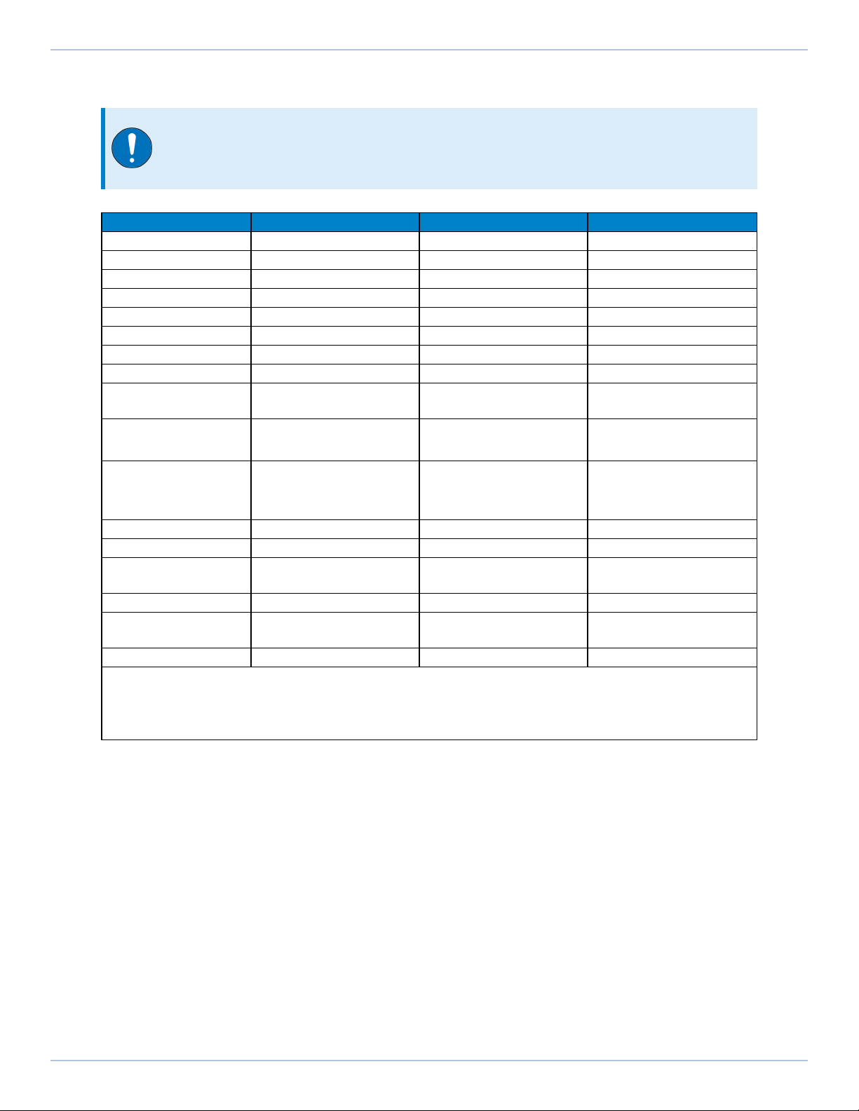
Table 1-2: Automation Motion Server Specifications (Control Cabinet / Desktop PC)
-CC05 -CC04 -DT01
Description Control cabinet PC Control cabinet PC Desktop PC
A3200 Version 6.x and above 6.x and above 6.x and above
Processor Intel i7-7700 Intel i5-7500 Intel i7-7700
RAM 16 GB 16 GB 16 GB
Operating System(1) Windows 10 LTSC Windows 10 LTSC Windows 10 64-bit
Hard Disk Space 256 GB SSD 128 GB SSD 512 GB SSD
USB 3.0 Connections 4 4 4
USB 2.0 Connections N/A N/A N/A
Input Power 24 VDC 24 VDC 100-240 V, 2-4 A,
50-60 Hz
Display Connections Display Port
HDMI
Display Port
HDMI
VGA
DVI-D(2)
Available PCI/PCIe
Expansion Slots (3) N/A N/A
1 x PCIe x16
2 x PCIe x4
3x PCI
DVD Drive No No Yes
Drive Interface HyperWire HyperWire HyperWire
LAN 10/100/1000 Mbit
(Qty. 2)
10/100/1000 Mbit
(Qty. 2)
10/100/1000 Mbit
(Qty. 2)
Modbus Support Yes (Ethernet) Yes (Ethernet) Yes (Ethernet)
EtherCAT/PROFINET
Support Available Available Available
Power Supply Optional ACAdapter Optional ACAdapter 180 W
(1) To avoid machine disruption, Aerotech disables automatic updates on Windows PCs that are shipped from Aerotech.
To customize your update settings, refer to Microsoft’s Windows documentation or Aerotech’s User Guide to Windows 10
Updates.
(2) Refer to Section 1.5. for configuration details.
(3) After the HyperWire card is installed.
1.1. Specifications Automation1 iPC Hardware Manual
10 www.aerotech.com
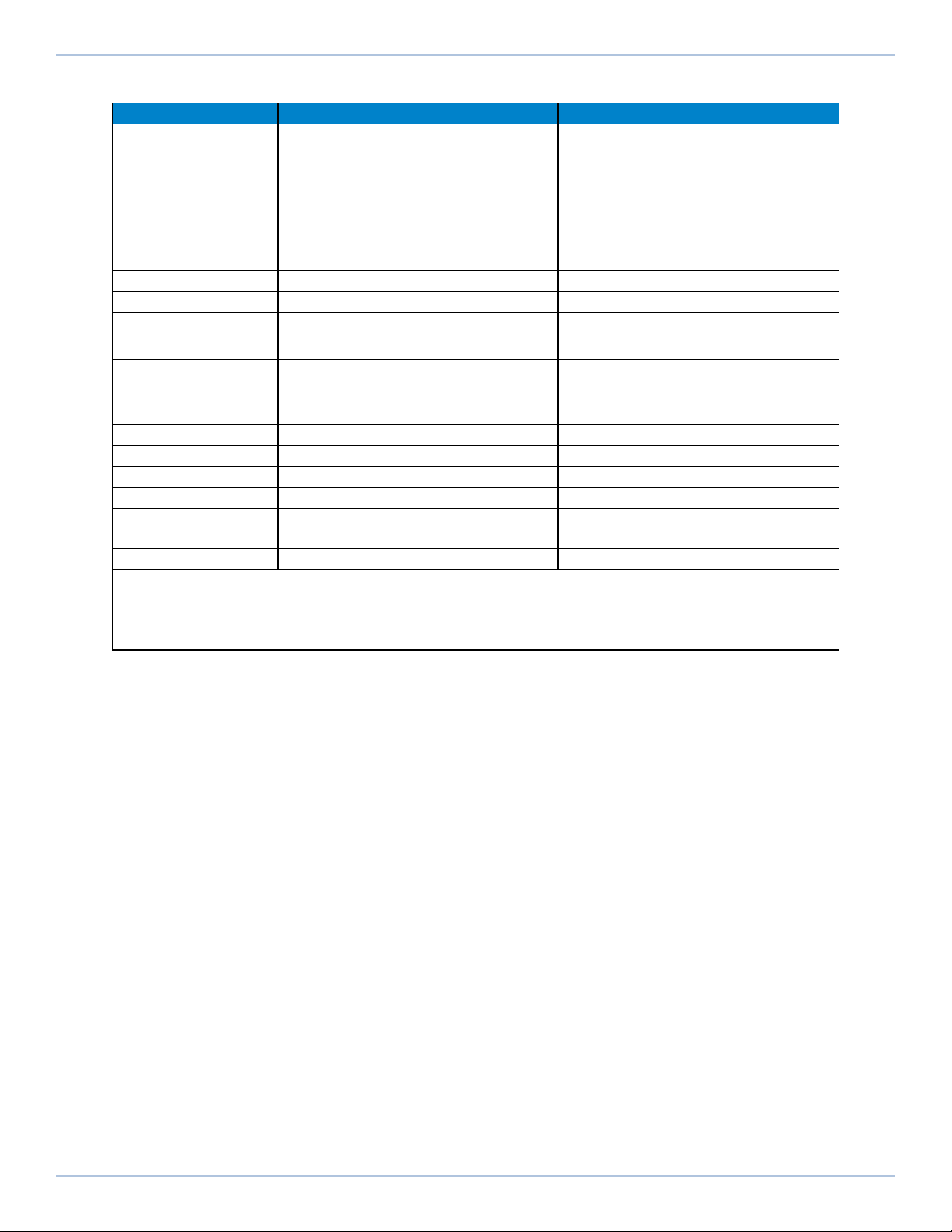
Table 1-3: Automation Motion Server Specifications (Rack Mount PCs)
-R103 -R402
Description 1U rack mount 4U rack mount
A3200 Version 6.x and above 6.x and above
Processor Intel i7-7700 Intel i7-7700
RAM 16 GB 16 GB
Operating System(1) Windows 10 64 bit Windows 10 64 bit
Hard Disk Space 256 GB SSD 512 GB SSD
USB 3.0 Connections 4 4
USB 2.0 Connections N/A N/A
Input Power 100-240 V, 2-4 A, 50-60 Hz 100-240 V, 2-4 A, 50-60 Hz
Display Connections • VGA
• DVI-D(2)
• VGA
• DVI-D(2)
Available PCI/PCIe
Expansion Slots (3) N/A
• 1 x PCIe x16
• 2 x PCIe x4
• 3 x PCI
DVD Drive Yes Yes
Drive Interface HyperWire HyperWire
LAN 10/100/1000 Mbit (Qty. 2) 10/100/1000 Mbit (Qty. 2)
Modbus Support N/A Yes (Ethernet)
EtherCAT/PROFINET
Support N/A Available
Power Supply 350 W 400 W
(1) To avoid machine disruption, Aerotech disables automatic updates on Windows PCs that are shipped from Aerotech.
To customize your update settings, refer to Microsoft’s Windows documentation or Aerotech’s User Guide to Windows 10
Updates.
(2) Refer to Section 1.5. for configuration details.
(3) After the HyperWire card is installed.
www.aerotech.com 11
Automation1 iPC Hardware Manual 1.1. Specifications

1.2. Remote Server Operation
Only one of the available Ethernet ports will be configured for use with the remote server. Refer to the
figures below to determine which port you should use for each Automation1 iPC hardware
configuration.
Figure 1-1: -CC04/-CC05 Connector View (typical)
Figure 1-2: -DT01 Connector View (typical)
1.2. Remote Server Operation Automation1 iPC Hardware Manual
12 www.aerotech.com

Figure 1-3: -R103 Connector View (typical)
Figure 1-4: -R402 Connector View (typical)
www.aerotech.com 13
Automation1 iPC Hardware Manual 1.2. Remote Server Operation

1.3. Dimensions
IMPORTANT: Aerotech continually improves its product offerings; listed options may be
superseded at any time. All drawings and illustrations are for reference only and were
complete and accurate as of this manual’s release. Refer to www.aerotech.com for the
most up-to-date information.
Figure 1-5: Desktop Computer Dimensions (-DT01)
1.3. Dimensions Automation1 iPC Hardware Manual
14 www.aerotech.com
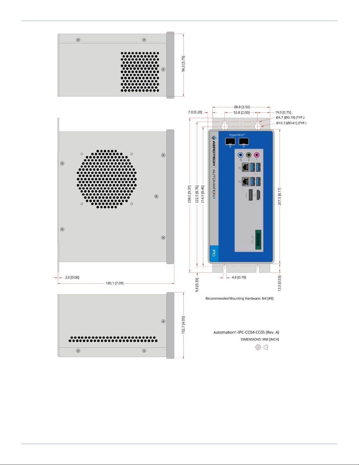
Figure 1-6: Control Cabinet Dimensions (-CC04/-CC05)
www.aerotech.com 15
Automation1 iPC Hardware Manual 1.3. Dimensions

Figure 1-7: 4U Rack Mount Chassis Dimensions (-R402)
1.3. Dimensions Automation1 iPC Hardware Manual
16 www.aerotech.com

Figure 1-8: 1U Rack Mount Chassis Dimensions (-R103)
www.aerotech.com 17
Automation1 iPC Hardware Manual 1.3. Dimensions

1.4. AC Power Setting
You can change the BIOS setting on the PC so that, in the event of a power failure, you will not need to
access the PC to manually turn the PCback on. Use this item to select AC power state when power is re-
applied after a power failure.
Table 1-4: BIOSSettings
PCType BIOSCategory Settings
-CC04
-CC05 State after G3 Power On
-R103 Restore ACPower Loss S0 State
-R402 Restore ACPower Loss S0 State
-DT01 Restore ACPower Loss S0 State
1.5. DVIMonitor Configuration (-R103, -R402, -DT01 PCOptions)
To let the Windows OS operate without a monitor connected, both the AIMB-785 motherboard and the
standard Advantech-provided BIOSare configured to report to the Windows OS that a VGAmonitor is
always connected as the default primary display. If you connect a single DVI monitor to one of the rack
mount (-R103 or -R402) or desktop (-DT01) computers, the BIOS will continue to report to Windows that
the VGA monitor is also connected. You will need to update the Windows Display settings to get the
system to correctly identify the DVI monitor. Either duplicate the Windows desktop to both monitors or
identify and set the DVI monitor as the primary display.
1.6. Environmental Specifications
Table 1-5: Environmental Specifications
Ambient
Temperature
Operating: 0° to 40°C
Storage: -30° to 85°C
Humidity
Non-condensing
The maximum relative humidity is 80% for temperatures that are less
than 31°C and decreases linearly to 50% relative humidity at 40°C.
Operating Altitude
0 m to 2,000 m above sea level.
If you must operate this product above 2,000 m or below sea level,
contact Aerotech, Inc.
Pollution Pollution Degree 2
Typically only nonconductive pollution occurs.
Operation Use only indoors
1.4. AC Power Setting Automation1 iPC Hardware Manual
18 www.aerotech.com

Appendix A: Warranty and Field Service
Aerotech, Inc. warrants its products to be free from harmful defects caused by faulty materials or poor
workmanship for a minimum period of one year from date of shipment from Aerotech. Aerotech’s
liability is limited to replacing, repairing or issuing credit, at its option, for any products that are returned
by the original purchaser during the warranty period. Aerotech makes no warranty that its products are
fit for the use or purpose to which they may be put by the buyer, whether or not such use or purpose
has been disclosed to Aerotech in specifications or drawings previously or subsequently provided, or
whether or not Aerotech’s products are specifically designed and/or manufactured for buyer’s use or
purpose. Aerotech’s liability on any claim for loss or damage arising out of the sale, resale, or use of any
of its products shall in no event exceed the selling price of the unit.
THE EXPRESS WARRANTY SET FORTH HEREIN IS IN LIEU OF AND EXCLUDES ALL OTHER WARRANTIES,
EXPRESSED OR IMPLIED, BY OPERATION OF LAW OR OTHERWISE. IN NO EVENT SHALL AEROTECH BE
LIABLE FOR CONSEQUENTIAL OR SPECIAL DAMAGES.
Return Products Procedure
Claims for shipment damage (evident or concealed) must be filed with the carrier by the buyer. Aerotech
must be notified within thirty (30) days of shipment of incorrect material. No product may be returned,
whether in warranty or out of warranty, without first obtaining approval from Aerotech. No credit will be
given nor repairs made for products returned without such approval. A "Return Materials Authorization
(RMA)" number must accompany any returned product(s). The RMA number may be obtained by calling
an Aerotech service center or by submitting the appropriate request available on our website
(www.aerotech.com). Products must be returned, prepaid, to an Aerotech service center (no C.O.D. or
Collect Freight accepted). The status of any product returned later than thirty (30) days after the
issuance of a return authorization number will be subject to review.
Visit https://www.aerotech.com/global-technical-support.aspx for the location of your nearest Aerotech
Service center.
Returned Product Warranty Determination
After Aerotech's examination, warranty or out-of-warranty status will be determined. If upon Aerotech's
examination a warranted defect exists, then the product(s) will be repaired at no charge and shipped,
prepaid, back to the buyer. If the buyer desires an expedited method of return, the product(s) will be
shipped collect. Warranty repairs do not extend the original warranty period.
Fixed Fee Repairs - Products having fixed-fee pricing will require a valid purchase order or credit
card particulars before any service work can begin.
All Other Repairs - After Aerotech's evaluation, the buyer shall be notified of the repair cost. At
such time the buyer must issue a valid purchase order to cover the cost of the repair and freight, or
authorize the product(s) to be shipped back as is, at the buyer's expense. Failure to obtain a
purchase order number or approval within thirty (30) days of notification will result in the product(s)
being returned as is, at the buyer's expense.
Repair work is warranted for ninety (90) days from date of shipment. Replacement components are
warranted for one year from date of shipment.
www.aerotech.com 19
Automation1 iPC Hardware Manual Appendix A: Warranty and Field Service

Rush Service
At times, the buyer may desire to expedite a repair. Regardless of warranty or out-of-warranty status,
the buyer must issue a valid purchase order to cover the added rush service cost. Rush service is subject
to Aerotech's approval.
On-site Warranty Repair
If an Aerotech product cannot be made functional by telephone assistance or by sending and having the
customer install replacement parts, and cannot be returned to the Aerotech service center for repair, and
if Aerotech determines the problem could be warranty-related, then the following policy applies:
Aerotech will provide an on-site Field Service Representative in a reasonable amount of time,
provided that the customer issues a valid purchase order to Aerotech covering all transportation and
subsistence costs. For warranty field repairs, the customer will not be charged for the cost of labor
and material. If service is rendered at times other than normal work periods, then special rates
apply.
If during the on-site repair it is determined the problem is not warranty related, then the terms and
conditions stated in the following “On-Site Non-Warranty Repair” section apply.
On-site Non-Warranty Repair
If any Aerotech product cannot be made functional by telephone assistance or purchased replacement
parts, and cannot be returned to the Aerotech service center for repair, then the following field service
policy applies:
Aerotech will provide an on-site Field Service Representative in a reasonable amount of time,
provided that the customer issues a valid purchase order to Aerotech covering all transportation and
subsistence costs and the prevailing labor cost, including travel time, necessary to complete the
repair.
Service Locations
http://www.aerotech.com/contact-sales.aspx?mapState=showMap
USA, CANADA, MEXICO
Aerotech, Inc.
Global Headquarters
Phone: +1-412-967-6440
Fax: +1-412-967-6870
CHINA
Aerotech China
Full-Service Subsidiary
Phone: +86 (21) 5508 6731
GERMANY
Aerotech Germany
Full-Service Subsidiary
Phone: +49 (0)911 967 9370
Fax: +49 (0)911 967 93720
TAIWAN
Aerotech Taiwan
Full-Service Subsidiary
Phone: +886 (0)2 8751 6690
UNITEDKINGDOM
Aerotech United Kingdom
Full-Service Subsidiary
Phone: +44 (0)1256 855055
Fax: +44 (0)1256 855649
Have your customer order number ready before calling.
Appendix A: Warranty and Field Service Automation1 iPC Hardware Manual
20 www.aerotech.com
This manual suits for next models
5
Table of contents
Other Aerotech Industrial PC manuals

Popular Industrial PC manuals by other brands

Contec
Contec IPC SERIES Operational manual

Advantech
Advantech MIC-1816 Series user manual

Neousys Technology
Neousys Technology Nuvo-7162GC Series user manual

IBASE Technology
IBASE Technology AMS310 user manual

Siemens
Siemens SIMATIC IPC847D Product information

GIGAIPC
GIGAIPC QBiX-Pro-ADLA1255H quick start guide

Chipsee
Chipsee PPC-A72-150-P manual

Moxa Technologies
Moxa Technologies V2406-24I Series Hardware user manual

National Instruments
National Instruments VXIpc-870 user manual

Asus
Asus Aaeon BOXER-8254AI user manual

IEI Technology
IEI Technology IVS-300-ULT3-i5/4G user manual

DFI
DFI DT122-SB installation guide


