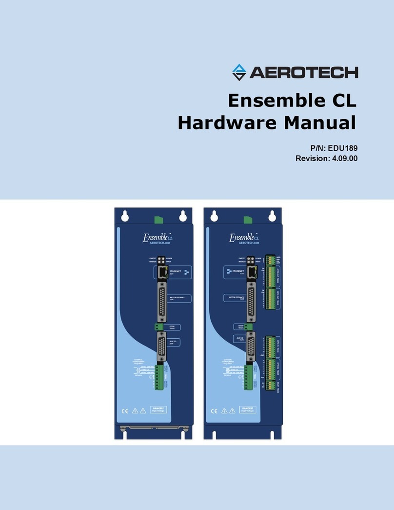
Aerotech Soloist CP User manual

P/N:EDU180
Revision: 4.05.00
Soloist CP
Hardware Manual
MOTOR FEEDBACK
J103
ESTOP
TB101
ENB/FLT
MARKER
AUX I/O
J104
MOTOR
FEEDBACK
J103
ESTOP
TB101
ENB/FLT
MARKER
RELAY TB206
NC
C
NO
OPTO IN TB205
OPTO IN TB204
C
0
1
2
3
4
5
6
7
GND
OPTO OUT TB203
OPTO OUT TB202
OP
OM
0
1
2
3
4
5
6
7
TB201
AGND
AIN+
AIN-
AOUT
AUX I/O
J104
AEROTECH.
COM
TMTM
AEROTECH.
COM
TMTM
C
0
1
2
3
4
5
6
7
+5V
OP
OM
0
1
2
3
4
5
6
7
ETHERNET
J102
ETHERNET
J102
High Voltage
DANGER!
MOTOR SUPPLY MOTOR OUTPUT
AC1
AC2
A
B
C
240V~
MAX
50/60Hz
15A MAX
PWR
INPOS
TB102
High Voltage
DANGER!
MOTOR SUPPLY MOTOR OUTPUT
AC1
AC2
A
B
C
240V~
MAX
50/60Hz
15A MAX
PWR
INPOS
TB102

Global Technical Support
Go to www.aerotech.com/global-technical-support for information and support about your Aerotech products. The website
provides downloadable resources (such as up-to-date software, product manuals, and Help files), training schedules, and PC-
to-PC remote technical support. You can also complete Product Return (RMA) forms and get information about repairs and
spare or replacement parts. For immediate help, contact a service office or your sales representative. Have your customer
order number available before you call or include it in your email.
United States (World Headquarters)
Phone: +1-412-967-6440
Fax: +1-412-967-6870
Email: service@aerotech.com
101 Zeta Drive
Pittsburgh, PA 15238-2897
www.aerotech.com
United Kingdom Japan
Phone: +44 (0)1256 855055
Fax: +44 (0)1256 855649
Email: service@aerotech.co.uk
Phone: +81 (0)50 5830 6814
Fax: +81 (0)43 306 3773
Email: service@aerotechkk.com.jp
Germany China
Phone: +49 (0)911 967 9370
Fax: +49 (0)911 967 93720
Email: service@aerotechgmbh.de
Phone: +86 (21) 3319 7715
Email: saleschina@aerotech.com
France Taiwan
Phone: +33 1 64 93 58 67
Email: sales@aerotech.co.uk
Phone: +886 (0)2 8751 6690
Email: service@aerotech.tw
This manual contains proprietary information and may not be reproduced, disclosed, or used in whole or in part without the
express written permission of Aerotech, Inc. Product names mentioned herein are used for identification purposes only and
may be trademarks of their respective companies.
Copyright © 2004-2015, Aerotech, Inc. All rights reserved.

Table of Contents Soloist CP
Table of Contents
Table of Contents iii
List of Figures v
List of Tables vii
EC Declaration of Conformity ix
Agency Approvals x
Safety Procedures and Warnings xi
Quick Installation Guide xiii
Chapter 1: Introduction 1
1.1. Drive and Software Compatibility 5
1.2. Electrical Specifications 6
1.2.1. System Power Requirements 7
1.2.2. Power Dissipation 8
1.3. Mechanical Design 9
1.4. Environmental Specifications 10
Chapter 2: Installation and Configuration 11
2.1. Power Connections 11
2.1.1. Control Supply Connections (TB106) 12
2.1.2. Motor Supply Connections (TB102) 13
2.1.3. Transformer Options 14
2.1.4. Minimizing Conducted, Radiated, and System Noise 21
2.2. Motor Output Connections 22
2.2.1. Brushless Motor Connections 23
2.2.1.1. Powered Motor Phasing 24
2.2.1.2. Unpowered Motor and Feedback Phasing 26
2.2.2. DC Brush Motor Connections 29
2.2.2.1. DC Brush Motor Phasing 30
2.2.3. Stepper Motor Connections 31
2.2.3.1. Stepper Motor Phasing 32
2.3. Motor Feedback Connections (J103) 33
2.3.1. Encoder Interface (J103) 34
2.3.1.1. RS-422 Line Driver Encoder (Standard) 35
2.3.1.2. EnDat Encoder Interface (J103) 36
2.3.1.3. Resolute Encoder Interface (J103) 37
2.3.1.4. Analog Encoder Interface 38
2.3.1.5. Encoder Phasing 40
2.3.2. Hall-Effect Interface (J103) 42
2.3.3. Thermistor Interface (J103) 43
2.3.4. Encoder Fault Interface (J103) 44
2.3.5. End Of Travel Limit Input Interface (J103) 45
2.3.5.1. End Of Travel Limit Phasing 47
2.3.6. Brake Output (J103) 48
2.4. Emergency Stop Sense Input (TB101) 49
2.4.1. Typical ESTOP Interface 50
2.5. Auxiliary I/O Connector (J104) 51
2.5.1. Auxiliary Encoder Channel (J104) 52
2.5.2. Position Synchronized Output (PSO)/Laser Firing (J104) 54
2.5.3. Opto-Isolated Outputs (J104) 56
2.5.4. Opto-Isolated Inputs (J104) 58
2.5.5. High Speed User Inputs 4-5 (J104) 60
www.aerotech.com iii

iv www.aerotech.com
2.5.6. Analog Output 0 (J104) 61
2.5.7. Analog Input 0 (J104) 62
2.6. Brake Power Supply (TB103) 63
2.6.1. Solid State Relay Specifications (TB103) 66
2.7. RS-232 Interface (TB103) 67
2.8. -EXTSHUNT Option (TB104) 68
2.9. PC Configuration and Operation Information 71
Chapter 3: -I/O Expansion Board 73
3.1. Analog Output (TB201) 74
3.2. Analog Input (TB201) 75
3.3. Opto-Isolated Inputs (TB204, TB205) 76
3.4. Opto-Isolated Outputs (TB202, TB203) 79
3.5. User Power (TB204, TB205) 83
3.6. Brake / Mechanical Relay (TB206) 84
3.6.1. Brake Configuration Jumpers 84
3.6.2. Mechanical Relay Specifications 84
3.6.3. Brake / Mechanical Relay Interface Connector 85
Chapter 4: Standard Interconnection Cables 87
4.1. Joystick Interface 88
4.2. Handwheel Interface 91
Chapter 5: Maintenance 93
5.1. Control Board 94
5.2. Preventative Maintenance 96
Appendix A: Warranty and Field Service 97
Appendix B: Revision History 99
Index 101
Soloist CP Table of Contents

Table of Contents Soloist CP
List of Figures
Figure 1-1: Soloist CP Networked Digital Drive 1
Figure 1-2: Functional Diagram 4
Figure 1-3: Power Dissipation vs. Output Current 8
Figure 1-4: Ambient Temperature vs. Power Dissipation 8
Figure 1-5: Dimensions 9
Figure 2-1: Control Supply Connections 12
Figure 2-2: Motor Bus Input Connections 13
Figure 2-3: Transformer Examples 14
Figure 2-4: 40 VDC Motor Power with a TV0.3-28-56-ST Transformer 15
Figure 2-5: 80 VDC Motor Power with a TV0.3-28-56-ST Transformer 16
Figure 2-6: 40 Volt DC Bus from 115 and 230 VAC Source 17
Figure 2-7: 80 Volt DC Bus from 115 and 230 VAC Source (TV0.3-56) 18
Figure 2-8: 160 Volt DC Bus from 115 and 230 VAC Source (TV0.3-56) 19
Figure 2-9: Control and Motor Power Wiring using a TM3 or TM5 Transformer 20
Figure 2-10: ACLine Filter (UFM-ST) 21
Figure 2-11: Brushless Motor Configuration 23
Figure 2-12: Encoder and Hall Signal Diagnostics 25
Figure 2-13: Motor Phasing Oscilloscope Example 26
Figure 2-14: Hall Phasing with Oscilloscope 27
Figure 2-15: Brushless Motor Phasing Goal 28
Figure 2-16: DC Brush Motor Configuration 29
Figure 2-17: Clockwise Motor Rotation 30
Figure 2-18: Stepper Motor Configuration 31
Figure 2-19: Clockwise Motor Rotation 32
Figure 2-20: Line Driver Encoder Interface (J103) 35
Figure 2-21: Serial Data Stream Interface 36
Figure 2-22: Serial Data Stream Interface 37
Figure 2-23: Analog Encoder Phasing Reference Diagram 38
Figure 2-24: Analog Encoder Interface (J103) 39
Figure 2-25: Encoder Phasing Reference Diagram (Standard) 40
Figure 2-26: Position Feedback in the DiagnosticDisplay 41
Figure 2-27: Hall-Effect Inputs (J103) 42
Figure 2-28: Thermistor Interface Input (J103) 43
Figure 2-29: Encoder Fault Interface Input (J103) 44
Figure 2-30: End of Travel Limit Input Connections 45
Figure 2-31: End of Travel Limit Interface Input (J103) 46
Figure 2-32: Limit Input Diagnostic Display 47
Figure 2-33: ESTOPSenseInput (TB101) 49
Figure 2-34: Typical Emergency Stop Circuit 50
Figure 2-35: Auxiliary Encoder Channel (J104) 53
Figure 2-36: PSOInterface 55
Figure 2-37: Outputs Connected in Current Sinking Mode (J104) 57
Figure 2-38: Outputs Connected in Current Sourcing Mode (J104) 57
Figure 2-39: Inputs Connected in Current Sinking Mode (J104) 59
Figure 2-40: Inputs Connected in Current Sourcing Mode (J104) 59
Figure 2-41: High Speed User Inputs (J104) 60
Figure 2-42: Analog Output 0 (J104) 61
Figure 2-43: Analog Input 0 (J104) 62
Figure 2-44: Brake Connected to J103 64
Figure 2-45: Brake Connected to TB103 65
Figure 2-46: RS-232 Interface (TB103) 67
www.aerotech.com v

vi www.aerotech.com
Figure 3-1: Soloist CP with -IO Option Board 73
Figure 3-2: Analog Output 1 Connector (TB201) 74
Figure 3-3: Analog Input Typical Connection (TB201) 75
Figure 3-4: Opto-Isolated Inputs 77
Figure 3-5: Inputs Connected to a Current Sourcing Device 78
Figure 3-6: Inputs Connected to a Current Sinking Device 78
Figure 3-7: Opto-Isolated Outputs (-IOBoard) 80
Figure 3-8: Outputs Connected in Current Sourcing Mode 81
Figure 3-9: Outputs Connected in Current Sinking Mode 82
Figure 3-10: Brake Connected to J103 85
Figure 3-11: Brake Connected to TB206 86
Figure 4-1: Single Axis Joystick Interface (to Aux I/O) 88
Figure 4-2: Two Axis Joystick Interface (to the Aux I/O of two drives) 89
Figure 4-3: Two Axis Joystick Interface (to the Aux I/O and I/O Board) 89
Figure 4-4: Two Axis Joystick Interface (to the I/Oboard of two drives) 90
Figure 4-5: Handwheel Interconnection (to Aux I/O) 91
Figure 4-6: Handwheel Interconnection (to Aux I/O via a BBA32 Module) 91
Figure 5-1: Control Board Assembly 94
Soloist CP Table of Contents

Table of Contents Soloist CP
List of Tables
Table 1-1: FeatureSummary 2
Table 1-2: Accessories 3
Table 1-3: Soloist Drive and Software Compatibility 5
Table 1-4: Electrical Specifications 6
Table 1-5: Physical Specifications 9
Table 1-6: Heat Sink Specifications 9
Table 2-1: Control Supply ACInput Wiring 12
Table 2-2: Control Supply Mating Connector 12
Table 2-3: Motor Supply Mating Connector 13
Table 2-4: Nominal Motor Operating Voltages / Required ACVoltages 14
Table 2-5: TransformerOptions 14
Table 2-6: Motor Supply Input Wiring 21
Table 2-7: UFM-STElectrical Specifications 21
Table 2-8: Motor Power Output Connections (TB102) 22
Table 2-9: Motor Power Output Mating Connector 22
Table 2-10: Wire Colors for Aerotech Supplied Cables (Brushless) 23
Table 2-11: Wire Colors for Aerotech Supplied Cables (DCBrush) 29
Table 2-12: Wire Colors for Aerotech Supplied Cables (Stepper) 31
Table 2-13: Motor Feedback Connector Pin Assignment (J103) 33
Table 2-14: Encoder Interface Pin Assignment 34
Table 2-15: Analog Encoder Specifications 38
Table 2-16: Hall-Effect Feedback Interface Pin Assignment (J103) 42
Table 2-17: Hall-Effect Feedback Interface Pin Assignment (J103) 43
Table 2-18: Encoder Fault Interface Pin Assignment (J103) 44
Table 2-19: End of Travel Limit Input Interface Pin Assignment (J103) 45
Table 2-20: Brake Output Pin Assignment (J103) 48
Table 2-21: Electrical Noise Suppression Devices 49
Table 2-22: Electrical Noise Suppression Devices 49
Table 2-23: TB101 Mating Connector 49
Table 2-24: Typical ESTOPRelay Ratings 50
Table 2-25: Auxiliary I/O Connector Pin Assignment (J104) 51
Table 2-26: Auxiliary Encoder Channel Pin Assignment (J104) 52
Table 2-27: PSOOutput Pin Assignment (J104) 54
Table 2-28: PSO Output Sources 54
Table 2-29: Port 0 Digital Output Connector Pin Assignment (J104) 56
Table 2-30: Digital Output Specifications 56
Table 2-31: Port 0 Digital Input Connector Pin Assignment (J104) 58
Table 2-32: PS2806-4 Opto-Device Specifications 58
Table 2-33: Port 0 High Speed Digital Input Connector Pin Assignment (J104) 60
Table 2-34: Input Voltage Jumper Configuration 60
Table 2-35: Analog Output Connector Pin Assignment (J104) 61
Table 2-36: Analog Input Connector Pin Assignment (J104) 62
Table 2-37: Brake Output Connector Pin Assignment (TB103) 63
Table 2-38: Mating Connector (TB103) 63
Table 2-39: Brake Output Connector Pin Assignment (J103) 63
Table 2-40: Relay Specifications 66
Table 2-41: RS-232 Connector Pin Assignment (TB103) 67
Table 2-42: RS-232 Port Connector Mating Connector (TB103) 67
Table 2-43: Recommended Shunt Resistors and Wire Gauge 68
Table 2-44: External Shunt Mating Connector 68
Table 2-45: Maximum Storage Energy 69
www.aerotech.com vii

viii www.aerotech.com
Table 3-1: -IO Expansion Board Jumper Configuration 73
Table 3-2: -IO Option Board Fuse Information 73
Table 3-3: Analog Output Connector Pin Assignment (TB201) 74
Table 3-4: Analog Output Mating Connector 74
Table 3-5: Analog Inputs Connector Pin Assignment (TB201) 75
Table 3-6: Analog Input Mating Connector 75
Table 3-7: PS2806-4 Opto-Device Specifications 76
Table 3-8: Port 1 Opto-Isolated Input Connector Pin Assignment (TB204) 76
Table 3-9: Port 2 Opto-Isolated Input Connector Pin Assignment (TB205) 76
Table 3-10: Opto-Isolated Input Mating Connector 76
Table 3-11: Port 1 Opto-Isolated Output Connector Pin Assignment (TB202) 79
Table 3-12: Port 2 Opto-Isolated Output Connector Pin Assignment (TB203) 79
Table 3-13: Opto-Isolated Output Mating Connector 79
Table 3-14: Output Specifications (TB202, TB203) 81
Table 3-15: User Common Connector Pin Assignment (TB204) 83
Table 3-16: +5 Volt Power Connector Pin Assignment (TB205) 83
Table 3-17: -IO Expansion Board Brake Jumper Configuration 84
Table 3-18: Voltage and Current Specifications (TB206) 84
Table 3-19: Brake / Mechanical Relay Connector Pin Assignment (TB206) 85
Table 3-20: Mating Connector 85
Table 3-21: Brake / Mechanical Relay Connector Pin Assignment (J103) 85
Table 4-1: Standard Interconnection Cables 87
Table 4-2: Cable Part Numbers 90
Table 5-1: LEDDescription 93
Table 5-2: Control Board Jumper Configuration 95
Table 5-3: Control Board Fuse Information 95
Table 5-4: LEDDescription 95
Table 5-5: Preventative Maintenance 96
Soloist CP Table of Contents

Declaration of Conformity Soloist CP
EC Declaration of Conformity
Manufacturer
Aerotech, Inc.
Address
101 Zeta Drive
Pittsburgh, PA 15238-2897
USA
Product
Soloist CP
Model/Types
All
This is to certify that the aforementioned product is in accordance with the applicable requirements of the
following Directive(s):
2004/108/EC Electromagnetic Compatibility Directive
2006/95/EC Low Voltage Directive
2011/65/EU RoHS2 Directive
and has been designed to be in conformity with the applicable requirements of the following documents
when installed and used in accordance with the manufacturer’s supplied installation instructions.
EN 55011 RFI Limits and Measurement
EN 61800-3 EMC requirements for power drives
EN 61000-3-2 Harmonic Current Emissions
EN 61000-3-3 Voltage Fluctuation and Flicker
EN 61000-4-2 ESD Immunity
EN 61000-4-3 Radiated RFI/EMI Immunity
EN 61000-4-4 EFT/Burst Immunity
EN 61000-4-5 Surge Immunity
EN 61000-4-6 Conducted Immunity
EN 61000-4-11 Voltage Dips and Interruptions
EN 61010-1 Safety requirements for electrical equipment
Name
/ Alex Weibel
Position
Engineer Verifying Compliance
Location
Pittsburgh, PA
Date
July 9, 2015
www.aerotech.com ix

x www.aerotech.com
Agency Approvals
Aerotech, Inc. Model Soloist CP Series Digital Drives have been tested and found to be in accordance to the
following listed Agency Approvals:
Approval / Certification: CUS NRTL
Approving Agency: TUV SUD America Inc.
Certificate #: U8 13 11 68995 013
File / Report #: 090-1309372-000
Standards: UL 61010-1; CAN/CSA-C22.2 No. 61010-1
Soloist CP Declaration of Conformity

Electrical Safety Soloist CP
Safety Procedures and Warnings
The following statements apply wherever the Warning or Danger symbol appears within this manual. Failure
to observe these precautions could result in serious injury to those individuals performing the procedures
and/or damage to the equipment.
N O T E : Read this manual in its entirety before installing, operating, or servicing this product. If you do
not understand the information contained herein, contact an Aerotech representative before proceeding.
Strictly adhere to the statements given in this section and other handling, use, and operational information
given throughout the manual to avoid injury to you and damage to the equipment.
N O T E : Aerotech continually improves its product offerings; listed options may be superseded at any
time. All drawings and illustrations are for reference only and were complete and accurate as of this
manual’s release. Refer to www.aerotech.com for the most up-to-date information.
D A N G E R : This product contains potentially lethal voltages. To reduce the possibility of
electrical shock, bodily injury, or death the following precautions must be followed.
1. Disconnect electrical power before servicing equipment.
2. Disconnect electrical power before performing any wiring.
3. Access to the Soloist CP and component parts must be restricted while connected to a
power source.
4. To minimize the possibility of electrical shock and bodily injury, extreme care must be
exercised when any electrical circuits are in use. Suitable precautions and protection must
be provided to warn and prevent persons from making contact with live circuits.
5. Install the Soloist CP inside a rack or enclosure.
6. Do not connect or disconnect any electrical components or connecting cables while
connected to a power source.
7. Make sure the Soloist CP and all components are properly grounded in accordance with
local electrical safety requirements.
8. Operator safeguarding requirements must be addressed during final integration of the
product.
D A N G E R : The Soloist CP case temperature may exceed 70°C in some applications.
www.aerotech.com xi

xii www.aerotech.com
W A R N I N G : To minimize the possibility of electrical shock, bodily injury or death the
following precautions must be followed.
1. Use of this equipment in ways other than described by this manual can cause personal
injury or equipment damage.
2. Moving parts can cause crushing or shearing injuries. Access to all stage and motor parts
must be restricted while connected to a power source.
3. Cables can pose a tripping hazard. Securely mount and position all system cables to avoid
potential hazards.
4. Do not expose the Soloist CPto environments or conditions outside of the listed
specifications. Exceeding environmental or operating specifications can cause damage to
the equipment.
5. If the Soloist CP is used in a manner not specified by the manufacturer, the protection
provided by the Soloist CP can be impaired and result in damage, shock, injury, or death.
6. Operators must be trained before operating this equipment.
7. All service and maintenance must be performed by qualified personnel.
8. The Soloist CP is intended for light industrial manufacturing or laboratory use. Use of the
Soloist CP for unintended applications can result in injury and damage to the equipment.
Soloist CP Electrical Safety

Quick Installation Guide Soloist CP
Quick Installation Guide
This chapter describes the order in which connections and settings should typically be made to the Soloist
CP. If a custom interconnection drawing was created for your system (look for a line item on your Sales
Order under the heading “Integration”), that drawing can be found on your installation device.
S/N -
P/N -
MOTOR
FEEDBACK
J103
ESTOP
TB101
ENB/FLT
MARKER
RELAY TB206
NC
C
NO
OPTO IN TB205
OPTO IN TB204
C
0
1
2
3
4
5
6
7
GND
OPTO OUT TB203
OPTO OUT TB202
OP
OM
0
1
2
3
4
5
6
7
TB201
AGND
AIN+
AIN-
AOUT
AUX I/O
J104
EXTERNAL
SHUNT
TB104
1 2
50/60Hz
85-240V~
0.25A MAX
TB106
CONTROL
SUPPLY
AC2AC1
1 2 3
AEROTECH.
COM
TMTM
C
0
1
2
3
4
5
6
7
+5V
OP
OM
0
1
2
3
4
5
6
7
ETHERNET
J102
WARNING:
DISCONNECT POWER BEFORE
SERVICING
HAZARDOUS VOLTAGES PRESENT
UP TO 8 MIN. AFTER POWER IS
DISCONNECTED
TB103
+5V / 0.5A
RS232 TX
RS232 RX
GND
BRAKE PS –
BRAKE PS +
USB J101
High Voltage
DANGER!
MOTOR SUPPLY MOTOR OUTPUT
AC1
AC2
A
B
C
240V~
MAX
50/60Hz
15A MAX
PWR
INPOS
TB102
Connect the Motor Outputs (TB102) and Motor Feedback (J103).
Connect the PC to either the Ethernet (J102) or the USB (J101).
Connect any additional I/O as required (not shown).
Connect to the Control Supply (TB106).
Connect to the Motor Supply (TB102).
Note: Connect to ESTOP (TB101) in this step if applicable.
1
5
1
1
2
3
4
5
2
5
4
2
Figure 1: Quick Start Connections
Topic Section
Motor Output Section 2.2. Motor Output Connections
Motor Feedback Section 2.3. Motor Feedback Connections (J103)
Ethernet / USB No Section / Standard Connection
Control Supply Section 2.1.1. Control Supply Connections (TB106)
Motor Supply Section 2.1.2. Motor Supply Connections (TB102)
Additional I/O User / Application dependent
www.aerotech.com xiii

Soloist CP Quick Installation Guide
xiv www.aerotech.com
This page intentionally left blank.

Introduction Soloist CP
Chapter 1: Introduction
Aerotech’s Soloist CP(Compact PWM) network digital drive is a high performance amplifier.The drive
provides deterministic behavior, auto-identification, and easy software setup. The Soloist CP’s high
performance double precision floating point DSP controls the digital PID and current loops. All system
configuration is done using software-settable parameters, including control loop gains and system safety
functions.
The Soloist CP is offered with an optional encoder interpolation feature (-MXU), an auxiliary square wave
encoder input for dual loop control, dedicated analog and digital I/O (expandable with the -IO option), and
separate power connections for motor and control supply voltages.
S/N -
P/N -
MOTOR
FEEDBACK
J103
ESTOP
TB101
ENB/FLT
MARKER
RELAY TB206
NC
C
NO
OPTO IN TB205
OPTO IN TB204
C
0
1
2
3
4
5
6
7
GND
OPTO OUT TB203
OPTO OUT TB202
OP
OM
0
1
2
3
4
5
6
7
TB201
AGND
AIN+
AIN-
AOUT
AUX I/O
J104
EXTERNAL
SHUNT
TB104
1 2
50/60Hz
85-240V~
0.25A MAX
TB106
CONTROL
SUPPLY
AC2AC1
1 2 3
AEROTECH.
COM
TM
TM
C
0
1
2
3
4
5
6
7
+5V
OP
OM
0
1
2
3
4
5
6
7
ETHERNET
J102
WARNING:
DISCONNECT POWER BEFORE
SERVICING
HAZARDOUS VOLTAGES PRESENT
UP TO 8 MIN. AFTER POWER IS
DISCONNECTED
TB103
+5V / 0.5A
RS232 TX
RS232 RX
GND
BRAKE PS –
BRAKE PS +
USB J101
Standard
Connector Description
J101 USB Port
J102 Ethernet Port
J103 Motor Feedback
J104 Auxiliary I/O
TB102 Motor Supply
TB102 Motor Output
TB106 Control Supply Output
TB101 Emergency Stop Sense Input (ESTOP)
TB103 RS232/Brake Power Supply
TB104 External Shunt
-IO/-IOH Board Option
Connector Description
TB201 Analog I/O
TB202 Opto-Outputs
TB203 Opto-Outputs
TB204 Opto-Inputs
TB205 Opto-Inputs
TB206 Relay
High Voltage
DANGER!
MOTOR SUPPLY MOTOR OUTPUT
AC1
AC2
A
B
C
240V~
MAX
50/60Hz
15A MAX
PWR
INPOS
TB102
Figure 1-1: Soloist CP Networked Digital Drive
www.aerotech.com Chapter 1 1

2 Chapter 1 www.aerotech.com
Table 1-1: FeatureSummary
Standard Features
lLine driver square wave quadrature encoder input for position and velocity feedback
lLine driver square wave auxiliary quadrature encoder input or output for PSO
lFour opto-isolated user outputs
lSix opto-isolated user inputs(two high speed)
lOne 16-bit differential analog input (±10 V)
lOne 16-bit analog output (±10 V)
lDedicated 5-24 V Emergency Stop sense input
l85 - 240 VAC control supply inputs
lOne fail-safe brake
lSingle axis Position Synchronized Output (PSO)
lAbsolute Encoder support
lCalibration (refer to the SoloistHelp file for more information)
lCamming (refer to the SoloistHelp file for more information)
l10/100 BASE-T Ethernet port for use with Ethernet I/O modules
Options
-S Internal shunt resistor network (standard on CP 30). A shunt circuit prevents the
bus voltage from causing damage to the amplifier (available for high-energy
systems).
40 W Continuous; 400 W Peak (5 seconds)
-IO lOne 16-bit analog output (±10 V)
lOne 12-bit differential analog input
lOne fail-safe brake or user relay output
l16 optically isolated logic inputs (5 - 24 VDC), may be connected in current
sourcing or sinking mode
l16 optically isolated logic outputs (5 - 24 VDC), user defined as current
sourcing or sinking
-MXU Interpolation circuit allowing for analog sine wave input on the standard encoder
channel. Interpolation factor: 4,096
-EXTSHUNT Connection provided for an external shunt resistor network. A shunt circuit
prevents the bus voltage from causing damage to the amplifier (available for high-
energy systems).
Soloist CP Introduction

Introduction Soloist CP
Table 1-2: Accessories
Accessories
UFM-ST AC Line Filter Module (required for CE compliance; refer to Section 2.1.)
MCK-NDRIVE Mating connector kit for J103 (J104 mate is always provided)
JI Industrial Joystick (NEMA12 (IP54) rated); refer to Section 4.1.
PS24-1 24 VDC, 1Apower supply for optional brake/relay output
BRAKE24-2 24 VDC, 2 A power supply for optional brake
Transformers
Refer to Section 2.1.3. for listings, wiring, and specifications
Cables
Interconnection A complete list of Aerotech cables can be found on the website at
http://www.aerotechmotioncontrol.com/manuals/index.aspx
Joystick/Handwheel Refer to Section 4.1. or Section 4.2.
www.aerotech.com Chapter 1 3

4 Chapter 1 www.aerotech.com
The following block diagram shows a connection summary. For detailed connection information, refer to
Chapter 2 and Chapter 3.
Emergency Stop Sense Input
Analog Input 1 +/-
Analog Output 1
16 Opto Outputs
(Sinking or Sourcing)
16 Opto Inputs
Brake Power
Input or Relay
(jumper configurable)
TB201
-IO Option
TB202 /
TB203
Opto Out
TB204 /
TB205
Opto In
TB206
Relay
Encoder +5V / Common
Brake ±
SIN, COS, MRK (RS422)
CW, CCW, Home Limits
Encoder Fault
Hall A, B, C
Motor Over Temperature
-MXU
Option
J103
Motor
Feedback
Analog Output 0
Analog Input 0 +/-
2 High Speed Opto Inputs
4 Opto Inputs
4 Opto Outputs
SIN, COS, MRK (RS422)
Encoder +5V / Common
PSO Output, Encoder Echo
USB 1.1 Port
J101
J104
Aux I/O
Ethernet Port
J102
TB101
ESTOP
Isolated
Power Supply
TB106
Control Supply
TB103
RS232 /
Brake Supply
TB104
-EXTSHUNT
option
Brake Supply
Input
RS232
+5V /
Common
PWM Power
Amplifier
Heatsink Over
Temperature A
+
B
C
Inrush
Limiting
TB102
Motor
Supply
TB102
Motor
Output
AC1
AC2
AC1
AC2
AC1
AC2
AC1
AC2
A
B
C
Figure 1-2: Functional Diagram
Soloist CP Introduction

Introduction Soloist CP
1.1. Drive and Software Compatibility
The following table lists the available Soloist drives and which version of the Soloist software first provided
support for a given drive. Drives that list a specific version number in the Last Software Version column will
not be supported after the listed version.
Table 1-3: Soloist Drive and Software Compatibility
Drive Type Firmware Revision First Software Version Last Software Version
CL - 2.06 Current
A 2.55 Current
CP
- 1.00 Current
A 2.01 Current
B 2.54 Current
HLe - 2.51 Current
HPe - 2.51 Current
ML - 3.00 Current
MP - 2.01 Current
A 2.55 Current
www.aerotech.com Chapter 1 5

6 Chapter 1 www.aerotech.com
1.2. Electrical Specifications
Table 1-4: Electrical Specifications
Description CP 10 CP 20 CP 30
Motor
Supply
Input Voltage 14-240 VAC
Input Frequency 50-60 Hz
Inrush Current 32 A @ 230 VAC; 16 A @ 115 VAC
Maximum
Continuous Input
Current
5 Arms 10 Arms 10 Arms
Input Current Refer to Section 1.2.1. System Power Requirements
Control
Supply
Input Voltage 85-240 VAC
Input Frequency 50-60 Hz
Inrush Current 26 A
Input Current .25 A max
Output Voltage (1) 20-340 VDC
Peak Output Current (1 second) 10 A 20 A 30 A
Continuous Output Current 5 A 10 A 10 A
Power Amplifier Bandwidth 2500 Hz maximum (software selectable)
Power Amplifier Efficiency 85% - 95% (2)
PWM Switching Frequency 20 kHz
Minimum Load Inductance 0.1 mH @160 VDC (1 mH @ 320 VDC)
User Power Supply Output 5 VDC (@ 500 mA)
Modes of Operation Brushless; Brush; Stepper
Protective Features Output short circuit; Peak over current; DC bus over voltage; RMS
over current; Over temperature; Control power supply under voltage;
Power stage bias supply under voltage
Isolation Optical and transformer isolation between control and power stages.
(1) AC input voltage and load dependent.
(2) Dependent on total output power: efficiency increases with increasing output power.
Soloist CP Introduction
Table of contents
Other Aerotech Network Hardware manuals