11
This system supplies a breathable gas stream consisting of an elevated oxygen content relative to
normalatmosphericcontent ofapproximately21%O2byvolume. Thistechnique employsgasseparation
technologyutilizingapermeablemembraneto separatecertaingas moleculesfromother gasmolecules
allowinga controlledflow ofoutput gassesof differingoxygen concentrations.
Thissystem producesDNAx Nitroxin oxygenconcentrations of22% to40% atmaximum pressuresof
3200- 3700PSI. A supplygas, inthis case,“Grade-E”air,will berequired. Thissupply gasis fedatlow
pressure(145-185 PSI)to theinput portof themembrane. Thegasstreamis fedthrough athermostat-
controlled heater. As the gas moves through this assembly, its temperature is raised to
35° (110 degrees F). The purpose of this heater is to even out the variations in gas temperature and
produce a more linear performance curve. Once through the heater, the input gas is allowed to pass
through the membrane. As the gas passes through the membrane, the gas volume applies pressure
againstthe insidewallsof thepermeablefibers resultinginthe migrationacrossthe wallofvarying levels
of the different constituents of air. Gas volumes of desired O2concentrations are achieved in this
manner. In this stage the normal oxygen content of the “Grade-E” air second the norms UNI EN 132,
CGA-Eand DIN 3188(20.9%) israised tooutput percentagesupwardsof 23%to 40%.
A needle valve in the outlet stream of the waste gas (nitrogen) controls the relative O2concentrations
whileinput pressureregulationallows controloftheoutputvolume ofthemembrane. This outletvolume
control is required to balance the input requirements of the high-pressure compressor. As the gas
volume of desired oxygen concentration is produced it is contained and directed to the inlet port of the
high-pressurecompressor. Anoverpressure checkvalveisinstalledin theinletfittingof thehigh-pressure
compressor to protect the compressor from over pressurization of the first stage. Negative pressure
protectionisaccomplishedinthesamemannerby installinganunder-pressurecheckvalvein theambient
air intake side of the membrane output fitting.
As the gas volume is subsequently compressed, it is alternately cooled and raised in pressure again
until it reaches its final design output pressure. Final filtration and purification is accomplished at final
compressordischarge.
Product gas “DNAx” nitrox is available at desired oxygen concentrations (up to 40% O2by volume) at
maximum pressures of 3200 - 3700 PSI, for filling Nitrox Storage Bottles or SCUBA cylinders.
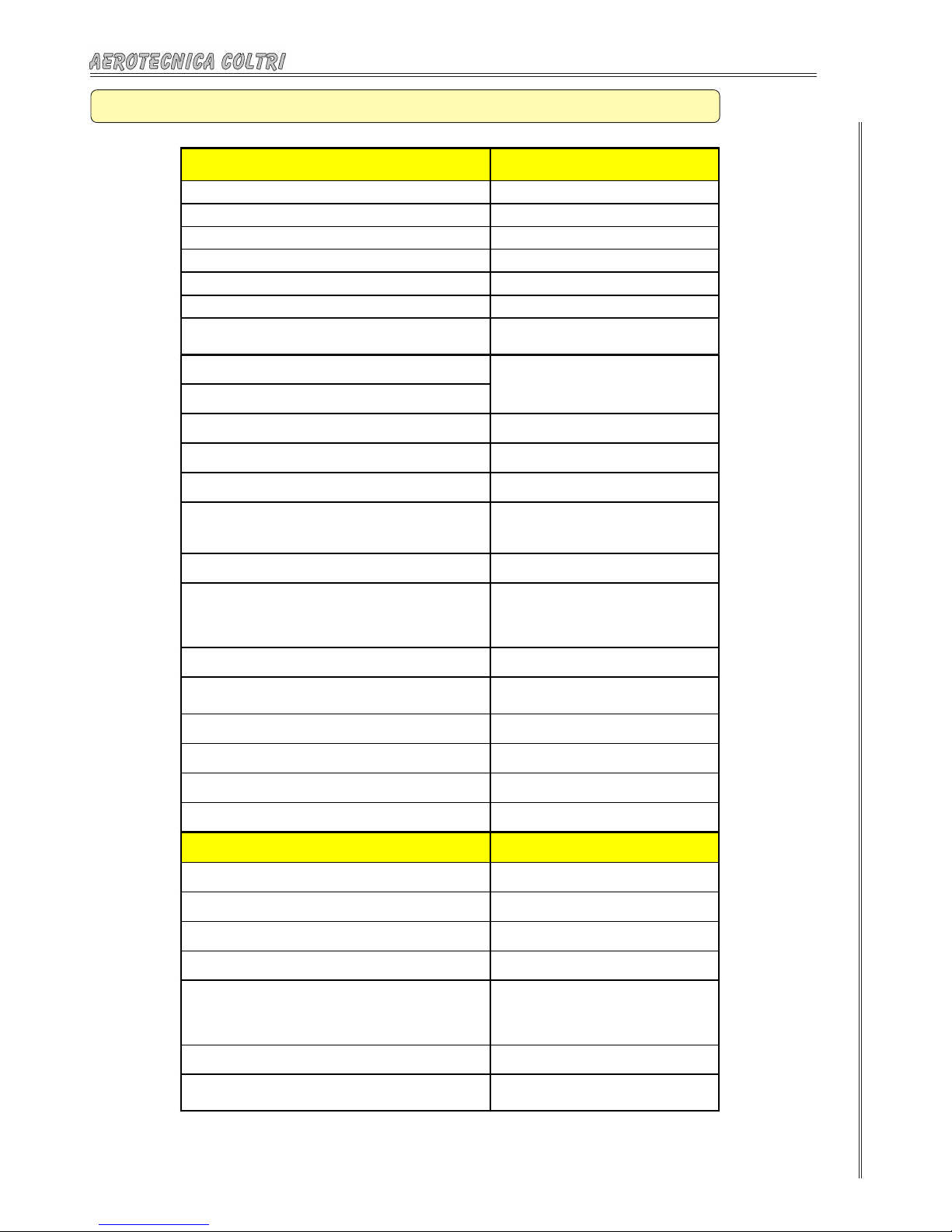
Typical Specification for Air :
O2Percentage: ..................................20-22%
CO2:.................................................1000 PPM
CO: ..................................................10 PPM
Hydrocarbons:..................................25 PPM
Water:..............................................67 PPM
DewPoint: .......................................- 50° F
Oil & Particles:................................. 5mg/m3
Odor:................................................Nessuno
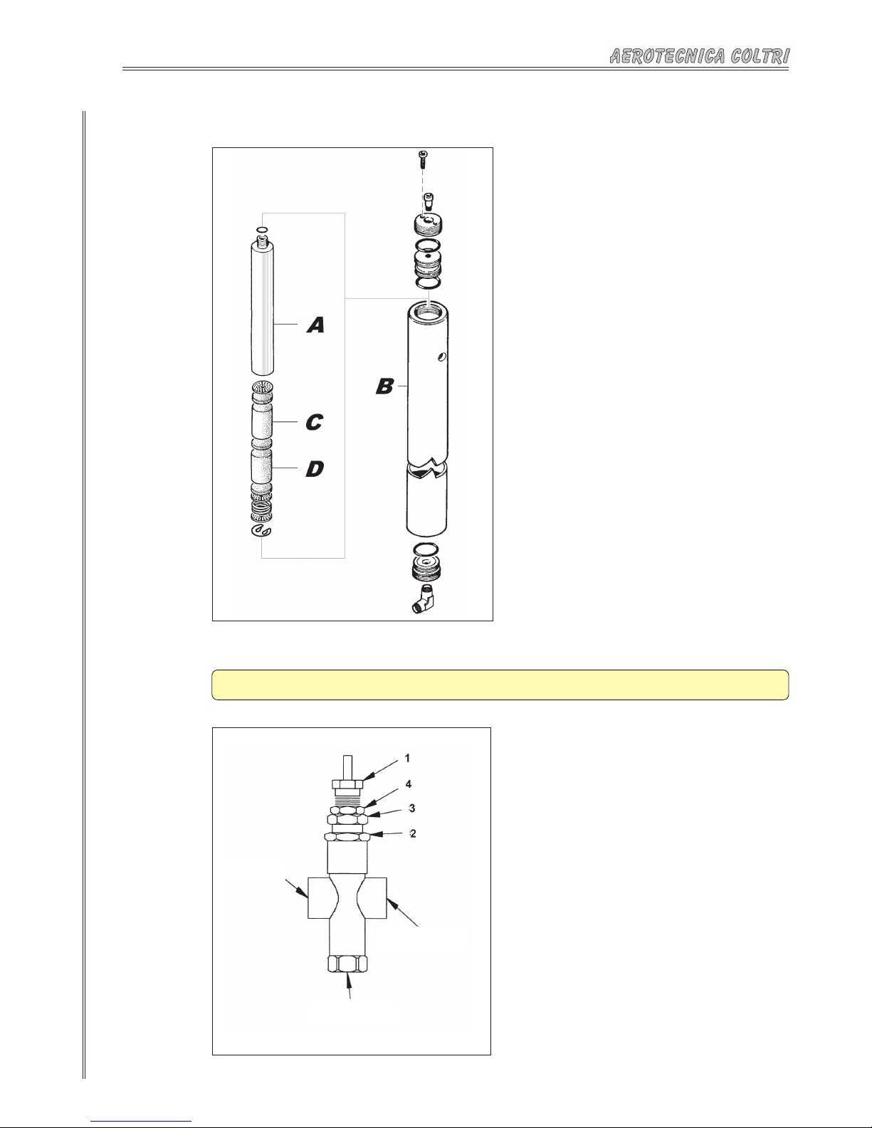
Technical description