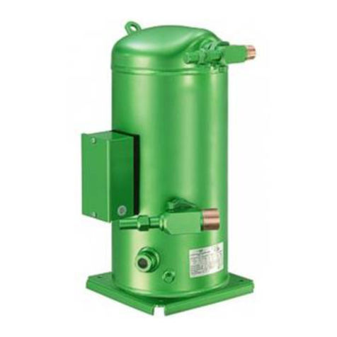
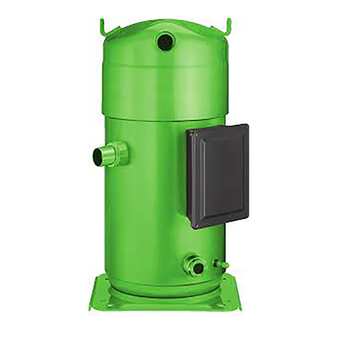
manuals.online logo
Brands
  1. Home
  2. •
  3. Brands
  4. •
  5. Bitzer
  6. •
  7. Air Compressor
  8. •
  9. Bitzer 2Q-4.2Y Manual

Bitzer 2Q-4.2Y Manual

KT-220-2
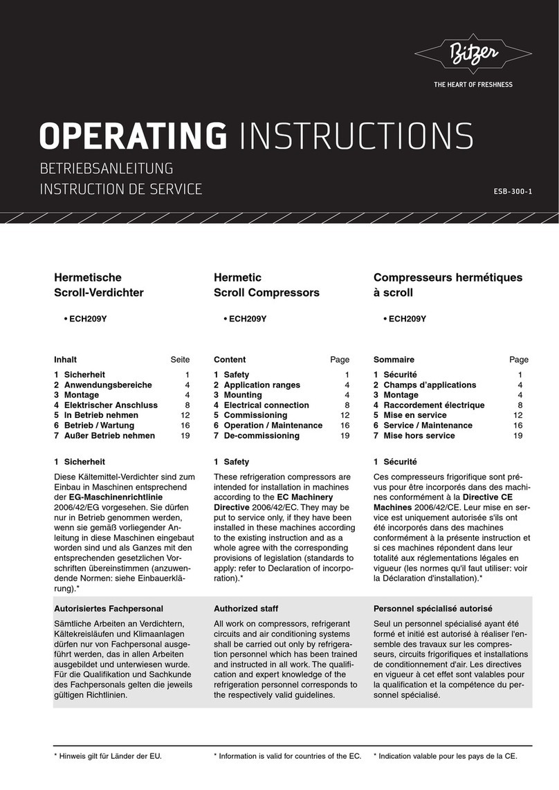
•4DES-7.F3Y•4CES-9.F3Y•4VES-7.F3Y .. 4NES-20.F4Y•4MTC-10.F4K, 4KTC-10.F4K1Allgemeines3Technische Daten4Elektrischer Anschluss1Allgemeines•Höhere System •Erhöhte Verdichter-Lebensdauer•4DES-7.F3Y•4CES-9.F3Y•4VES-7.F3Y .. 4NES-20.F4Y•4MTC-10.F4K, 4KTC-10.F4K1General3Technical data4Electrical connection1GeneralFrequency inverters (FI) are increas-ingly used to adapt the compressorcapacity to the actual cooling demandof the system. The motor speed of thecompressor is continuously adjustedby a frequency inverter in an addition-frequency inverter:•Increased system efficiency, espe-cially in the case of partial load•Extended compressor life as a•4DES-7.F3Y•4CES-9.F3Y•4VES-7.F3Y .. 4NES-20.F4Y•4MTC-10.F4K, 4KTC-10.F4K1Généralités3Caractéristiques techniques4Raccordement électrique6Messages de fonctionnement 1Généralités•Efficacité plus élevée du système, •Durée de service prolongée du com-
ТЕХНИЧЕСКАЯ ИНФОРМАЦИЯ
KT-140-7 RUS
Zusatzkühlung
Inhalt
1 Sicherheit 1
2 Zusatzventilatoren 3
3 Wassergekühlte
Zylinderköpfe 10
1 Sicherheit
Im Bereich hoher thermischer Belas-
tung kann eine zusätzliche Kühlung
des Verdichters erforderlich werden
(siehe Einsatzgrenzen in Prospekten
und BITZER Software). In der vorlie-
genden Technischen Information wer-
den die Anwendungs- und Montage-
hinweise für die wichtigsten Kühlungs-
arten behandelt (Zusatzventilatoren,
wassergekühlte Zylinderköpfe).
Diese Technische Information während
der gesamten Verdichter-Lebensdauer
aufbewahren.
Folgende technische Dokumente
ebenfalls beachten
KB-104 (Betriebsanleitung)
KB-110 (Betriebsanleitung)
KW-100 (Wartungsanleitung)
Autorisiertes Fachpersonal
Sämtliche Arbeiten an Verdichtern und
Kälteanlagen dürfen nur von Fach-
personal ausgeführt werden, das in
allen Arbeiten ausgebildet und unter-
wiesen wurde. Für die Qualifikation
und Sachkunde des Fachpersonals
gelten die jeweils landesüblichen Vor-
schriften und Richtlinien.
Additional cooling
Content
1 Safety 1
2 Additional fans 3
3 Water cooled cylinder
heads 10
1 Safety
It may be necessary to provide sup-
plementary cooling for the compressor
when subjected to high thermal load
(refer to application limits in brochures
and BITZER Software). This Technical
Information deals with instructions
for the use and assembly of the main
cooling methods (additional fan,
water-cooled cylinder heads).
Retain this Technical Information
during the entire lifetime of the
compressor.
Also observe the following technical
documents
KB-104 (Operating Instructions)
KB-110 (Operating Instructions)
KW-100 (Maintenance Instructions)
Authorized staff
All work on compressor and refrigera-
tion systems shall be carried out only
by refrigeration personnel which has
been trained and instructed in all
work. The qualification and expert
knowledge of the refrigeration per-
sonnel is subject to the respective
national regulations and guidelines.
Дополнительное охлаждение
Содержание
1 Правила техники безопасности 1
2 Дополнительный вентилятор 3
3 Водоохлаждаемые головки
цилиндров 10
1 Правила техники безопасности
В случаях высоких тепловых нагрузок
может потребоваться дополнительное
охлаждение компрессора (см. области
применения в проспектах и BITZER
Software). В данной технической инфор-
мации представлены рекомендации
по применению и монтажу основных
систем охлаждения (дополнительный
вентилятор и водоохдаждаемые головки
цилиндров).
Сохраняйте данную техническую
информацию в течение всего срока
службы компрессора.
Также соблюдайте указания
следующей тех. документации
KB-104 (Инструкция по эксплуатации)
KB-110 (Инструкция по эксплуатации)
KW-100 (Инструкция по техническому
обслуживанию)
Специалисты, допускаемые к работе
К выполнению работ на компрессорах
и холодильных агрегатах допускаются
только специалисты по холодильным
установкам прошедшие обучение
и инструктаж на все виды работ.
Квалификация и знания специалистов
должны соответствовать действующим
директивам.
2 KT-140-7 RUS
Restgefahren
Vom Verdichter können unvermeidbare
Restgefahren ausgehen.
Jede Person, die an diesem Gerät
arbeitet, muss deshalb diese
Technische Information sorgfältig
lesen!
Es gelten zwingend
schriften und Normen (z.B. EN 378,
EN 60204 und EN 60335),
Sicherheitsregeln,
Sicherheitshinweise
sind Anweisungen um Gefährdungen
zu vermeiden.
Sicherheitshinweise genauestens
einhalten!
!
!
Achtung!
Anweisung um eine mögliche
Gefährdung von Geräten zu
vermeiden.
Vorsicht!
Anweisung um eine mögliche
minderschwere Gefährdung von
Personen zu vermeiden.
!Warnung!
Anweisung um eine mögliche
schwere Gefährdung von
Personen zu vermeiden.
Gefahr!
Anweisung um eine unmittelbare
schwere Gefährdung von
Personen zu vermeiden.
Allgemeine Sicherheitshinweise
!Warnung!
Der Verdichter ist im Ausliefe-
rungszustand mit Schutzgas ge-
füllt (Überdruck ca. 0,2.. 0,5 bar).
Bei unsachgemäßer Handhabung
sind Verletzungen von Haut und
Augen möglich.
Bei Arbeiten am Verdichter
Schutzbrille tragen!
Anschlüsse nicht öffnen, bevor
Überdruck abgelassen ist.
Residual hazards
Certain residual hazards from the
compressors are unavoidable.
All persons working on these units
must therefore read these Technical
Information carefully!
All of the following have validity:
standards (e.g. EN 378, EN 60204
and EN 60335),
standards,
Safety references
are instructions intended to prevent
hazards.
Safety references must be stringently
observed!
!
!
Attention!
Instructions on preventing
possible damage to equipment.
Caution!
Instructions on preventing
a possible minor hazard to
persons.
!Warning!
Instructions on preventing
a possible severe hazard to
persons.
Danger!
Instructions on preventing an
immediate risk of severe hazard
to persons.
General safety references
!Warning!
The compressor is under pres-
sure with a holding charge to a
pressure of 0.2 to 0.5 bar above
atmospheric pressure.
Incorrect handling may cause
injury to skin and eyes.
Wear safety goggles while work-
ing on compressor.
Do not open connections before
down.
Остаточная опасность
Компрессор может являться источником
остаточной опасности.
Поэтому все работающие на этом
оборудовании должны внимательно
изучить данную техническую
информацию!
Обязательные для соблюдения
предписания:
• соответствующие правила техники
безопасности и нормы (напр., EN 378,
EN 60204 и EN 60335),
• общие правила техники безопасности,
• предписания ЕС,
• национальные правила.
Указания по технике безопасности
это инструкции, направленные на
исключение угроз опасности.
Следует неукоснительно соблюдать
указания по технике безопасности!
!
!
Внимание!
Указание для предотвращения
возможного повреждения
оборудования.
Осторожно!
Указание для предотвращения
возможной незначительной
опасности для персонала.
!
Предупреждение!
Указание для предотвращения
возможной серьезной опасности
для персонала.
Опасность!
Указание для предотвращения
непосредственной серьезной
опасности для персонала.
Общие указания по технике
безопасности
!
Предупреждение!
Компрессор в состоянии поставки
наполнен защитным газом с
избыточным давлением от 0,2 до
0,5 бара выше атмосферного
давления. Неправильное обра-
щение может вызвать повреждение
кожных покровов и глаз. При работе
с компрессором одевайте защитные
очки.
Не открывайте присоединительные
элементы до полного сброса
избыточного давления.
3KT-140-7 RUS
Bei Arbeiten am Verdichter nach
Inbetriebnahme der Anlage:
!Warnung!
Verdichter steht unter Druck!
Bei unsachgemäßen Eingriffen
sind schwere Verletzungen
möglich.
Verdichter auf drucklosen
Zustand bringen!
Schutzbrille tragen!
Nach Montage des Zusatzventilators:
!
!
Achtung!
Nach falscher Montage kann
Kältemittel oder Öl entweichen.
Inbetriebnahme auf Kältemittel-
Dichtheit prüfen!
2 Zusatzventilatoren
Diese Art der Kühlung ist universell
einsetzbar. Sie bietet gleichmäßige
Kühlwirkung und lässt sich in ihrer
Funktion auf einfache Weise überwa-
chen (durch elektrische Absicherung).
In der Regel wird der Lüfter elektrisch
parallel zum Verdichter geschaltet.
Wenn der Verdichter im Luftstrom
des Verflüssigerlüfters aufgestellt ist
(mindestens 3 m/s), kann auf einen
Zusatzlüfter verzichtet werden.
NH3-Verdichter erfordern
wassergekühlte Zylinderköpfe
zur Zusatzkühlung (Standardaus-
führung, Zusatzventilatoren
können nur unter Einschränkun-
gen und nach Rücksprache mit
BITZER verwendet werden).
For any work on the compressor after
system has been commissioned:
!Warning!
Compressor is under pressure!
In case of improper handling
severe injuries are possible.
Release the pressure from
compressor!
Wear safety goggles!
After mounting of the additional fan:
!
!
Attention!
After incorrect mounting
refrigerant or oil may escape.
Before commissioning check
compressor!
2 Additional fans
This cooling method can be used
universally. It offers a uniform cool-
ing effect and its performance can
be monitored easily (by means of
electrical protection). The fan is usu-
ally electrically connected in parallel
to the compressor. If the compres-
sor is located in the air stream of the
condenser fan (at least 3 m/s), it is not
necessary to install an auxiliary fan.
NH3compressors requires water
cooled cylinder heads for addi-
tional cooling (standard version,
additional fan can only be used
under restriction and after
consultation with BITZER).
Для любых работ на компрессоре после
ввода системы в эксплуатацию:
!
Предупреждение!
Компрессор находится под
давлением!
В случае неправильного обращения
возможны серьезные травмы.
Сбросьте давление в компрессоре!
Оденьте защитные очки!
После установки доп. вентилятора:
!
!
Внимание!
После неправильного монтажа
может произойти утечка масла или
хладагента.
Перед вводом в эксплуатацию
проверьте компрессор!
2 Дополнительный вентилятор
Этот метод охлаждения отличается
универсальным применением. Он
обеспечивает равномерное охлаждение
и легко контролируется при помощи
электронного защитного устройства.
Как правило, вентилятор и компрессор
подключаются параллельно. Если
компрессор обдувается воздушным
потоком вентилятора конденсатора
(как минимум 3 м/сек.), то в этом случае
можно отказаться от дополнительного
вентилятора.
Для компрессоров, работающих на
аммиаке в качестве доп.
охлаждения, используются
водоохлаждаемые головки
цилиндров (у данных компрессоров
в стандартном исполнении доп.
охлаждение с помощью
вентилятора может применяться
только в ограниченных случаях и
только после консультации с
BITZER).
4 KT-140-7 RUS
Abb. 1 Abmessungen und Montageposition
der Zusatzventilatoren
Fig. 1 Dimensions and mounting position
of the additional fans
Рис. 1 Размеры и позиции для монтажа
дополнительных вентиляторов
* Höhe des Ventilators mit Wechselstrom (Option). Bausatz-Nr.: 343 021 24 bzw. 343 021 25
* Height of the fan with AC (option). Kit No.: 343 021 24 resp. 343 021 25
* Высота вентилятора с AC (опция). Артикул №: 343 021 24 соотв. 343 021 25
400
303 (331*)
128
315 315
210
103
103
210
310
104
215
315
210
103
400
303 (331*)
128
2KES-05(Y).. 2FES-3(Y) 2EES-2(Y).. 2CES-4(Y),
2DES-3.F1Y
4FES-3(Y).. 4CES-9(Y),
4FE-5.F1Y.. 4CE-9.F3Y
4VE(S)-6Y.. 4NE(S)-20(Y)
4VES-10.F4Y.. 4NES-20.F4Y
4JE-13Y.. 4FE-35(Y)
6JE-22Y.. 6FE-50(Y)
4JE-13Y.. 4FE-35(Y)
6JE-22Y.. 6FE-50(Y)
4T.2(Y).. 4G.2(Y)
2T.2(Y).. 2N.2(Y)
6H.2(Y).. 6F.2(Y)
5KT-140-7 RUS
2.1 Zusatzventilator montieren
!Warnung!
Verdichter steht unter Druck!
Verdichter auf drucklosen
Zustand bringen!
Schutzbrille tragen!
Bei Montagearbeiten an den Zylinder-
köpfen:
!
!
Achtung!
Schrauben und Muttern un-
bedingt mit vorgeschriebenen
Drehmomenten anziehen (siehe
auch Wartungsanleitung
KW-100).
Die in Abb. 1 markierten Schrauben
am Zylinderkopf entfernen.



Ventilatorfuß direkt am Zylinder-
kopf befestigen (80 Nm).
2EES-2(Y)..2CES-4(Y) + CR II
Bei Einsatz des CRII-Systems,
Leistungsregelung für ECOLINE-
Verdichter, bei den Typen:

zusätzliches Ventilator-Befesti-
gungsblech und veränderte
Montageposition am Zylinderkopf
beachten (siehe dazu Abb. 2).
Befestigungsblech mit den
beiliegenden Schrauben an den
Zylinderkopf schrauben (80 Nm).
Ventilatorfüße befestigen.
Bausatznummer „Ventilator-
Befestigung CRII“: 320 396 09
2.2 Mounting the fan
!Warning!
Compressor is under pressure!
Release the pressure from
compressor!
Wear safety goggles!
Mounting works on cylinder heads:
!
!
Attention!
Tighten bolts and nuts with
the specified torques (see also
maintenance instructions
KW-100).
Remove the cylinder head screws
marked in fig. 1



Screw the fan foot directly onto the
cylinder head (80 Nm).
2EES-2(Y)..2CES-4(Y) + CR II
When using the CRII system,
capacity control for ECOLINE
compressors, for types:

please note the additional fan fixing
plate and the changed mounting
position at the cylinder head (for
more details, see fig. 2).
Screw fixing plate with the enclosed
screws onto the cylinder head
(80 Nm). Fix the fan feet.
Kit Number “fan fixing plate CRII”:
320 396 09
2.1 Монтаж дополнительного
вентилятора
!
Предупреждение!
Компрессор находится под
давлением!
Сбросьте давление в компрессоре!
Оденьте защитные очки!
При монтаже на головках цилиндров:
!
!
Внимание!
Затяните болты и гайки с
указанными моментами (также
см. инструкцию по обслуживанию
KW-100).
Удалите винты головок цилиндров
указанные на рис. 1
• 2KES-05(Y) .. 2FES-3(Y)
2EES-2(Y) .. 2CES-4(Y)
2DES-3.F1Y
Привинтите ножки вентилятора
непосредственно к головке цилиндров
(80 Nm).
2EES-2(Y) .. 2CES-4(Y) + CR II
При использовании системы
CRII, системы регулирования
производительности для
компрессоров ECOLINE, с моделями:
2EES-2(Y) .. 2CES-4(Y),
пожалуйста, обратите внимание на
крепежную пластину доп. вентилятора
и на измененное монтажное
положение на головке цилиндров
(для более подробной информации,
см. рис. 2). Привинтите крепежную
пластину с помощью прилагаемых
винтов к головке цилиндров (80 Nm).
Закрепите ножки вентилятора.
Номер артикула «CRII крепежная
пластина вентилятора»: 320 396 09
Abb. 2 2EES-2CES: Montageposition und
Befestigung des Zusatzventilators
bei Einsatz des CRII-Systems
Fig. 2 2EES-2CES: Mounting position and
fixing of the additional fan when
using the CRII system
Рис. 2 2EES-2CES: Монтажное положение
и крепление доп. вентилятора при
использовании системы CRII
508
6 KT-140-7 RUS




Befestigungsbleche mit den
beiliegenden Schrauben an die
Zylinderköpfe schrauben (80 Nm).
Ventilatorfüße befestigen (siehe
Abb. 1).


Zylinderkopfschrauben durch
Gewindebolzen ersetzen (80 Nm).
Darauf Befestigungsbleche auf-
stecken (Abb. 1).
Mit Federscheiben und Muttern
befestigen.
Ventilatorfüße anschrauben.
Alle Befestigungsbleche für die
Zylinderköpfe der ECOLINE-Baureihe
(Typen 4FES.. 6FE) sind rückwärts-
kompatibel.
!
!
Achtung!
Nach falscher Montage kann
Kältemittel oder Öl entweichen.
Inbetriebnahme auf Kältemittel-
Dichtheit prüfen! 


Screw the fixing plates with the
enclosed screws onto the cylinder
heads (80 Nm).
Fix the fan feet (see fig.1).

Replace the cylinder head screws
by threaded bolts (80 Nm). Fit the
fixing plates in the threaded bolts
according to (fig. 1).
Fasten with spring washers and
nuts.
Screw the fan feet.
All fixing plates for the cylinder
heads of the ECOLINE series (types
4FES..6FE) are backward compatible.
!
!
Attention!
After incorrect mounting
refrigerant or oil may escape.
Before commissioning check
compressor for refrigerant
tightness!
• 4FES-3(Y) .. 4CES-9(Y),
4VE(S)-6Y .. 4NE(S)-20(Y)
4FE-5.F1Y .. 4CE-9.F3Y
4VE-10.F4Y .. 4NE-20.F4Y
Привинтите крепежные пластины
с помощью прилагаемых винтов
к головкам цилиндров (80 Nm).
Закрепите ножки вентилятора
(см. рис. 1).
• 4JE-13Y .. 6FE-50(Y)
2T.2(Y) .. 6F.2(Y)
Замените винты на шпильки (80 Nm).
Установите крепежные пластины на
шпильки (см. рис. 1).
Закрепите их при помощи пружинных
шайб и гаек.
Привинтите опоры вентилятора.
Все крепежные пластины головок
цилиндров серии ECOLINE (типы
4FES .. 6FE) взаимозаменяемы.
!
!
Внимание!
После неправильного монтажа
может произойти утечка масла или
хладагента.
Перед вводом в эксплуатацию
проверьте компрессор на плотность!
7KT-140-7 RUS
387 Ø280
476
224343
273
309
554
349
Ø285
Ø285
417
504
259398
307
2.2 Abmessungen
ECOLINE-Verdichter
2.2 Dimensions
ECOLINE compressors
2.2 Размеры
Компрессоры ECOLINE
2KES-05(Y)..2FES-3(Y)
4FES-3(Y)..4CES-9(Y)
4FE-5.F1Y..4CE-9.F3Y
4JE-13Y..4FE-35(Y)
2EES-2(Y)..2CES-4(Y), 2DES-3.F1Y
4VE(S)-6Y..4NE(S)-20(Y)
4VE-10.F4Y..4NE-20.F4Y
6JE-22Y..6FE-50(Y)
* Höhe des Verdichters + Ventilator mit Wechselstrom (Option). Bausatz-Nr.: 343 021 24 bzw. 343 021 25
* Height of the compressor + fan with AC (option). Complete No.: 343 021 24 resp. 343 021 25
* Высота компрессора + вентилятор с AC (опция). Артикул №: 343 021 24 соотв. 343 021 25
439
502
696 (726*)
Ø344
303
Ø285
385
575
453
680 (708*)
445
Ø344
8 KT-140-7 RUS

















Offene Verdichter Open drive compressors
Открытые компрессоры
2T.2(Y).. 2N.2(Y)
4H.2(Y)..4G.2(Y)
4T.2(Y).. 4N.2(Y)
6H.2(Y)..6F.2(Y)
2.3 In Betrieb nehmen
Spannungs- und Frequenzangaben
auf dem Typenschild des Ventilator-
Motors mit den Daten des Strom-
netzes vergleichen. Motor nur bei
Übereinstimmung anschließen. Dreh-
richtung so wählen, dass der Zusatz-
ventilator von oben auf den Verdichter
bläst.
2.3 Commissioning
Compare the voltage and frequency
on the motor name plate with the
voltage supply data. Only connect the
motor if this data agree. Select the
rotation direction so that the air flows
directly onto the compressor.
2.3 Ввод в эксплуатацию
Сравните данные напряжения и частоты,
указанные на заводской табличке мотора
вентилятора с параметрами электросети.
Выберите такое направление вращения
лопастей дополнительного вентилятора,
чтобы поток воздуха шел от вентилятора
к компрессору сверху вниз.
9KT-140-7 RUS
2.4 Übersicht Ventilatoren 2.4 Overview of fans
2.4 Обзор вентиляторов
Typ
Type
Ти п
Bausatz-Nr.
Complete No.
Артикул №
Spannung
Voltage
Напряжение
±10%
Strom-
aufnahme
Current
consumpt.
Потребля-
емый ток
A
Leistungs-
aufnahme
Power
consumption
Потребл-
яемая
мощность
W
Luftmenge
Air volume
Объем.
расход
воздуха
m³/h
Schutzart
Enclosure
class
Класс
защиты
2KES-05(Y).. 2FES-3(Y) 343 021 01 230V-1-50 Hz
230V-1-60 Hz
0,46
0,54
60
72
970
1100 IP44
2EES-2(Y).. 2CES-4(Y) 
2DES-3.F1Y 343 021 26 230V-1-50 Hz
230V-1-60 Hz
0,53
0,55
100
120
2700
3100
4FES-3(Y).. 4CES-9(Y)
4FES-5.F1Y.. 4CES-6.F1Y
4DES-7.F3Y, 4CES-9.F3Y
343 021 29 230V-1-50 Hz
230V-1-60 Hz
0,53
0,55
100
120
2700
3100
4VES-6Y.. 4NES-20(Y)
4VE-6Y.. 4NE-20(Y)
4VES-10.F4Y.. 4NES-20.F4Y
343 021 27 230V-1-50 Hz
230V-1-60 Hz
0,53
0,55
100
120
2700
3100
2T.2(Y).. 2N.2(Y) 343 021 02
230 / 400V-3-50 Hz ∆/ Y
230 / 400V-3-60 Hz ∆/ Y
265 / 460V-3-60 Hz ∆/ Y
0,50 / 0,29
0,55 / 0,32
0,57 / 0,33
120
180
190
2200
2650
3050
4T.2(Y).. 4N.2(Y) 343 021 03
230 / 400V-3-50 Hz ∆/ Y
230 / 400V-3-60 Hz ∆/ Y
265 / 460V-3-60 Hz ∆/ Y
0,50 / 0,29
0,55 / 0,32
0,57 / 0,33
120
180
190
2200
2650
3050
4JE-13Y.. 4FE-35(Y) 343 021 22 230 / 400V-3-50 Hz ∆/ Y
230 / 400V-3-60 Hz ∆/ Y
265 / 460V-3-60 Hz ∆/ Y
0,50 / 0,29
0,55 / 0,32
0,57 / 0,33
120
180
190
2200
2650
3050
IP54
343 021 24 À230-1-50 Hz
230-1-60 Hz
0,59
0,82
130
190
2200
2650
4H.2(Y).. 4G.2(Y) 343 021 04 230 / 400V-3-50 Hz ∆/ Y
230 / 400V-3-60 Hz ∆/ Y
265 / 460V-3-60 Hz ∆/ Y
0,50 / 0,29
0,55 / 0,32
0,57 / 0,33
120
180
190
2200
2650
3050
6JE-22Y.. 6FE-50(Y) 343 021 23 230 / 400V-3-50 Hz ∆/ Y
230 / 400V-3-60 Hz ∆/ Y
265 / 460V-3-60 Hz ∆/ Y
0,50 / 0,29
0,55 / 0,32
0,57 / 0,33
120
180
190
2200
2650
3050
343 021 25 À230-1-50 Hz
230-1-60 Hz
0,59
0,82
130
190
2200
2650
6H.2(Y).. 6F.2(Y) 343 021 05 230 / 400V-3-50 Hz ∆/ Y
230 / 400V-3-60 Hz ∆/ Y
265 / 460V-3-60 Hz ∆/ Y
0,50 / 0,29
0,55 / 0,32
0,57 / 0,33
120
180
190
2200
2650
3050
Alle Ventilatoren mit Wicklungsschutz.
Andere Spannungen auf Anfrage.
ÀWechselstromausführung (Option)
Bei Einsatz des CRII-Systems,
Leistungsregelung für ECOLINE-
Verdichter, muss bei den Typen
sätzliches Befestigungsblech für
den Ventilator bestellt und montiert
werden (Bausatznummer „Ventilator-
Befestigung CRII“: 320 396 09).
All fans with winding protection.
Other voltages upon request.
ÀAC version (option)
When using the CRII system, capacity
control for ECOLINE compressors,
with the compressors types
fixing plate for the fan must be ordered
and mounted (kit number “fan fixing
plate CRII”: 320 396 09).
Все вентиляторы имеют защиту обмотки.
Другое напряжение по запросу.
À
AC версия (опция)

При использовании системы CRII, системы
регулирования производительности для
компрессоров ECOLINE, с моделями
2EES-2(Y) .. 2CES-4(Y), должна быть
заказана и смонтирована дополнительная
крепежная пластина для вентилятора
(номер артикула «CRII крепежная
пластина вентилятора»: 320 396 09).
10 KT-140-7 RUS
3 Wassergekühlte Zylinderköpfe
- NH3-Ausführung der offenen
Verdichter: W2TA..W6FA
Für korrosives Kühlwasser (z.B. See-
wasser) ist eine Kunststoff beschichte-
te Ausführung erhältlich.
3.1 Montage
Kühlwasser entsprechend Abbildung 2
anschließen.
Bei 4- und 6-Zylinder-Verdichtern ist
sowohl Reihen- als auch Parallel-
schaltung möglich. Bei Parallelschal-
tung darf die Mindest-Wassermenge
von 150 I/h für jeden Zylinderkopf
nicht unterschritten werden.
Kühlwasser-Temperatur

Das Kühlwasser für die Zylinder-
köpfe sollte aus dem bereits
erwärmten Kühlwasser des Ver-
flüssigers abgezweigt werden.

Die Kühlwasser-Temperatur soll-
te 50°C nicht übersteigen. In der
Regel ist die Wärmeabfuhr ausrei-
chend, wenn die Temperaturdiffe-
renz zwischen Kühlwasser-Eintritt
und -Austritt 5..10K oder der
Wasser-Durchsatz ca. 150 I/h
beträgt.
Stillstand des Verdichters
Beim Abschalten des Verdichters
muss der Kühlwasser-Zufluss zum
Zylinderkopf unterbrochen werden
(z.B. Wasserregler, Magnetventil),
um eine Rückkondensation von Kälte-
mittel in den Zylinderkopf zu ver-
meiden.
Flexible Leitungselemente
Bei elastischer Aufstellung des Ver-
dichters sollten flexible Leitungsele-
mente eingebaut werden (Abb. 2).
3 Water cooled cylinder heads
- NH3design of the open drive
compressors: W2TA.. W6FA
For corrosive cooling water (e.g. sea
water) a plastic-coated version is
available.
3.1 Assembly
Connect the cooling water according
to figure 2.
Four and six cylinder compressors
may be connected in series or in par-
allel. For parallel connection a mini-
mum water flow rate of 150 I/h at each
cylinder head must be ensured.
Cooling water temperature

The cooling water for the cylinder
heads should preferably be
supplied from the already warmed
cooling water of the condenser.

The cooling water temperature
must not exceed 50°C. Adequate
heat transfer is normally achieved
when the inlet/outlet water tem-
perature difference is between 5
and 10 K or with a water volume
fIow of approx. 150 l/h.
Compressor standstill
When the compressor is off, the
cooling water supply to the cylinder
heads must be interrupted (e.g. water
regulator, solenoid valve) to avoid
condensation of refrigerant back into
the cylinder head.
Flexible pipe elements
If the compressor is flexibly mounted,
the use of flexible pipe elements are
recommended (figure 2).
3 Водоохлаждаемые головки
цилиндров
• Опция для:
- 4J-13.2(Y) .. 6F-50.2(Y)
- 2T.2(Y) .. 6F.2(Y)
- III(Y) .. V(Y)
• Стандарт для:
- VI W(Y), VII W(Y)
- NH3 модификация открытых
компрессоров: W2TA .. W6FA
Для защиты от коррозийного воздействия
охлаждающей воды (например, морской
воды) доступно полимерное покрытие
охлаждающего тракта.
3.1 Сборка
Присоедините подвод охлаждающей
воды в соответствии с рис. 2.
Для 4-х и 6-ти цилиндровых компрес-
соров возможно последовательное
и параллельное подключение линий
охлаждения. При параллельном
подключении необходимо обеспечить
минимальный объемный расход воды
150 л/час на каждую головку цилиндров.
Температура охлаждающей воды
• На входе:
Охлаждающая вода для головок
цилиндров не должна смешиваться с
уже нагретой водой в конденсаторе.
• На выходе:
Температура охлаждающей воды не
должна превышать 50°C. Достаточный
отвод тепла, как правило, дости-
гается, если разница температур
между охлаждающей водой на входе
и на выходе составляет 5 .. 10 К или
при объемном расходе воды прим.
150 л/час.
Отключение компрессора
При выключении компрессора должна
быть прекращена подача охлаждающей
воды к головкам цилиндров (например,
при помощи регулятора расхода воды,
электромагнитного клапана), чтобы не
допустить конденсации хладагента в
головках цилиндров.
Гибкие соединительные патрубки
Для не жесткой установки компрессора
должны использоваться гибкие
соединительные патрубки (см. рис. 2).
11KT-140-7 RUS
Abmessungen
Die Verdichter-Abmessungen ändern
wassergekühlte Zylinderköpfe. Einzige
um maximal 1 cm zu.
Dimensions
The compressor dimensions do not
change by conversion to water cooled
cylinder heads. Only exception are
Here the height increases by 1 cm at
maximum.
Размеры
Размеры компрессора не меняются
от замены обычных головок на
водоохлаждаемые головки цилиндров.
Исключением являются компрессоры
III(Y), IV(Y) и V(Y). В этих случаях высота
компрессора увеличивается максимум
на 1 см.

 
 


   
     

 
    
 



  
     
 

 
 
   
      
   

 
   

    
1
3
2
PC
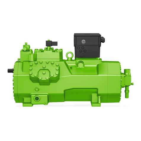
Abb. 3 Wassergekühlte Zylinderköpfe
anschließen
Fig. 3 Connecting the water cooled
cylinder heads
Рис. 3 Присоединение водоохлаждаемых
головок цилиндров
1 Drossel
Flow restrictor
Дроссель
2 flexible Leitungselemente
Flexible pipe elements
Гибкие соединительные патрубки
3 Wasserregler/Magnetventil
Water regulator/solenoid valve
Регулятор расхода воды / электромагнитный
клапан
BITZER Kühlmaschinenbau GmbH
Eschenbrünnlestraße 15 // 71065 Sindelfingen // Germany
Tel +49 (0)70 31 932-0 // Fax +49 (0) 70 31 9 32-1 47
bitzer@bitzer.de // www.bitzer.de
Subject to change // Änderungen vorbehalten // Toutes modifications réservées // 80420701 // 05.2010
Änderungen vorbehalten Subject to change Изменения возможны 80303803 02.2015
Subject to change // Änderungen vorbehalten /

Other Bitzer Air Compressor manuals

Bitzer HS.8851 User manual

Bitzer

Bitzer HS.8851 User manual

Bitzer HS.85 series Instructions for use

Bitzer

Bitzer HS.85 series Instructions for use

Bitzer ECH209Y User manual

Bitzer

Bitzer ECH209Y User manual

Bitzer HSK85 User manual

Bitzer

Bitzer HSK85 User manual

Bitzer F400 User manual

Bitzer

Bitzer F400 User manual

Bitzer 2DES-3.F1Y Technical specifications

Bitzer

Bitzer 2DES-3.F1Y Technical specifications

Bitzer KT-230-2 Manual

Bitzer

Bitzer KT-230-2 Manual

Bitzer 2KTE User manual

Bitzer

Bitzer 2KTE User manual

Bitzer OLC-D1-S Manual

Bitzer

Bitzer OLC-D1-S Manual

Bitzer OS.53 series User manual

Bitzer

Bitzer OS.53 series User manual

Bitzer ST-150-2 Manual

Bitzer

Bitzer ST-150-2 Manual

Bitzer CSVW2 User manual

Bitzer

Bitzer CSVW2 User manual

Bitzer Orbit 6 Series User manual

Bitzer

Bitzer Orbit 6 Series User manual

Bitzer ACP8551K-2 User manual

Bitzer

Bitzer ACP8551K-2 User manual

Bitzer 4TF Operating and maintenance instructions

Bitzer

Bitzer 4TF Operating and maintenance instructions

Bitzer OCTAGON Series User manual

Bitzer

Bitzer OCTAGON Series User manual

Bitzer HS.74 series Technical specifications

Bitzer

Bitzer HS.74 series Technical specifications

Bitzer ECOLINE User manual

Bitzer

Bitzer ECOLINE User manual

Bitzer 2T.2 Series User manual

Bitzer

Bitzer 2T.2 Series User manual

Bitzer KB-510-3 User manual

Bitzer

Bitzer KB-510-3 User manual

Bitzer CSH Series User manual

Bitzer

Bitzer CSH Series User manual

Bitzer CSH 65 Series User manual

Bitzer

Bitzer CSH 65 Series User manual

Bitzer OSK/N7441-EX User manual

Bitzer

Bitzer OSK/N7441-EX User manual

Bitzer 2T.2 Series Technical specifications

Bitzer

Bitzer 2T.2 Series Technical specifications

Popular Air Compressor manuals by other brands

KAESER ESD 442 SFC Technical documentation

KAESER

KAESER ESD 442 SFC Technical documentation

Craftsman 919.722010 owner's manual

Craftsman

Craftsman 919.722010 owner's manual

Craftsman 919.724321 owner's manual

Craftsman

Craftsman 919.724321 owner's manual

L&W LW 225 E operating instructions

L&W

L&W LW 225 E operating instructions

AEROTECNICA COLTRI MCH-36 Use and maintenance manual

AEROTECNICA COLTRI

AEROTECNICA COLTRI MCH-36 Use and maintenance manual

California Air Tools 10020- 220 owner's manual

California Air Tools

California Air Tools 10020- 220 owner's manual

TECH DAC001 owner's manual

TECH

TECH DAC001 owner's manual

Kenmore 8424 operating instructions

Kenmore

Kenmore 8424 operating instructions

Ozito ACK-1100 instruction manual

Ozito

Ozito ACK-1100 instruction manual

Brooks 8600 Quick installation guide

Brooks

Brooks 8600 Quick installation guide

VARO POWERPLUS POWX1730 manual

VARO

VARO POWERPLUS POWX1730 manual

Boss Industries BA435 Piston Service and maintenance user manual

Boss Industries

Boss Industries BA435 Piston Service and maintenance user manual

Westinghouse 5026 Instruction Pamphlet

Westinghouse

Westinghouse 5026 Instruction Pamphlet

ARB CKMTP12 operating instructions

ARB

ARB CKMTP12 operating instructions

Zipper Mowers ZI-COM50-10 user manual

Zipper Mowers

Zipper Mowers ZI-COM50-10 user manual

VIAIR 20008 user manual

VIAIR

VIAIR 20008 user manual

MARMON Campbell Hausfeld AC200100 Operating instructions and parts manual

MARMON

MARMON Campbell Hausfeld AC200100 Operating instructions and parts manual

XPOtool AS06 instruction manual

XPOtool

XPOtool AS06 instruction manual

manuals.online logo
manuals.online logoBrands
  • About & Mission
  • Contact us
  • Privacy Policy
  • Terms and Conditions

Copyright 2025 Manuals.Online. All Rights Reserved.