AERTECNICA TUBO ROBOCM189TR User manual

8TR1456/1
IT
D
Ø4 mm
INSTALLAZIONE
COMPONENTI IN DOTAZIONE
D- tubo rilevamento depressione
E- ingresso sensore
1- Effettuare con un trapano un foro passante sulla cassa della QB
con una punta Ø 4mm adeguata, alla distanza indicata.
Inserire il tubo rilevamento depressione (D) all’interno della QB.
2- Effettuare un secondo foro con la stessa punta Ø 4mm nel
raccordo curvo di ingresso polveri della centrale QB.
Inserire il tubo di rilevamento depressione (D) nell’ingresso sensore
(E) senza entrare dentro il raccordo curvo come indicato a lato
Ø4 mm D
D
SI
NO
E
NOTA BENE
In abitazioni composte di più
piani si consiglia di istallare
il ricevitore (R) nel piano
intermedio.
L’apparecchio ricevitore (R)
non può essere installato in
ambiente esterno all’abitazione
All’interno di un edicio il
raggio di azione tra ricevitore
(R) e trasmettitore (T) è di 15m.
e consente l’attraversamento di
2 solai (S1 - S2)
R
S1
S2
T
R
distanza ≥ 150cm
T - trasmettitore wireless per base ROBÒ
A - pulsante di avviamento/arresto
B - led di segnalazione wireless
C - batteria
D - supporto ssaggio trasmettitore con vite
A
B
T
V
E
C
D
F
R
FREQUENZA DI FUNZIONAMENTO 433,92 Mhz
POTENZA EFFETTIVA RADIO 0,3mW
TIPO DI MODULAZIONE ampiezza
(ON OFF)
ASSORBIMENTO IN
TRASMISSIONE 10mA
CONFORMITÀ ALLA DIRETTIVA 99/05/CE
Il radiocomando è conforme ai requisiti essenziali
ssati dalla Direttiva 99/05/CE.
Sono state applicate le seguenti Norme Tecniche:
EN 60335-1, EN 301489-3, EN 300220-3
E - tubo rilevamento depressione
F - cavo plug per attivazione prese
R - apparecchio Ricevitore wireless
V - viti con tasselli
T
R
INSTRUZIONI KIT WIRELESS TUBÒ | ROBÒ CM189TR
PER AVVIAMENTO/SPEGNIMENTO CENTRALE QB A PARETE
COMPLETO DI RICEVITORE E TRASMETTITORE (RIC.)
R
PROGRAMMAZIONE TRA TRASMETTITORE E RICEVITORE
CANCELLAZIONE PROGRAMMI IN MEMORIA
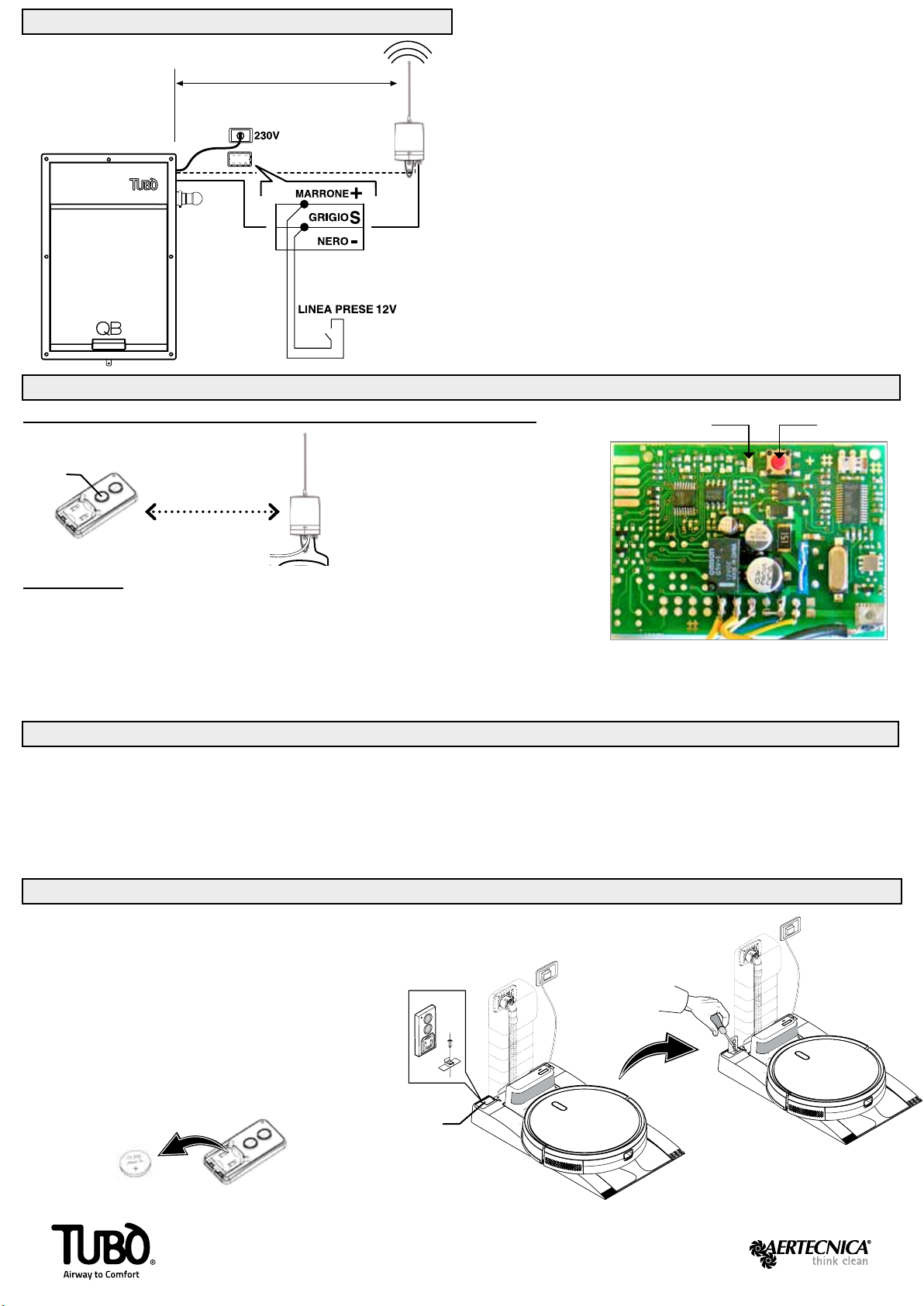
COLLEGAMENTO ELETTRICO QB CON RICEVITORE
2- Inserire una scatola di derivazione (Q) e cablare i cavi di collegamento
tra la centrale QB e il Ricevitore wireless (R).
1- Montare il Ricevitore wireless (R) alla parete ad una distanza minima
di 150 cm dalla centrale QB.
PROCEDURA A
1- scollegare la linea di alimentazione della centrale aspirante.
2- aprire l’apparecchio ricevitore (R)
3- estrarre la scheda elettronica (S)
4- riattivare la linea di alimentazione della centrale aspirante.
5- premere il tasto rosso (H), si accende il led (K).
6- premere entro 5 secondi il pulsante (A) di avviamento del trasmettitore (T).
1 - scollegare la linea di alimentazione della centrale QB.
2 - aprire l’apparecchio ricevitore (R), estrarre la scheda elettronica e premere
il tasto rosso (H).
3 - mentre il tasto è premuto ricollegare l’alimentazione della centrale.
4 - il led (K) si accende (colore rosso).
Linea attivazione 12V prese aspiranti
cavo marrone (+)
cavo grigio (S)
cavo nero (-)
ALIMENTAZIONE RICEVITORE WIRELLES
L’alimentazione dell’apparecchio ricevitore (R) è a 12 volt
Non esiste rischio di pericolo elettrico.
SCHEDA
ELETTRONICA
RICEVITORE
distanza ≥ 150 cm
HK
S
7- attendere qualche secondo per la memorizzazione del nuovo segnale;
il led (K) si spegne.
8- reinserire la scheda elettronica (S) e richiudere il ricevitore.
LA PROGRAMMAZIONE TRA TRASMETTITORE E RICEVITORE VIENE GIÀ IMPOSTATA DAL COSTRUTTORE
R
Q
(optional)
A
INSTALLAZIONE TRASMETTITORE SU BASE AUTOPULENTE ROBÒ
1 - togliere la batteria (C) interna al trasmettitore (T)
2 - inserire il trasmettitore (T) nel suo alloggiamento (G)
3 - bloccare il tramettitore inserendo il supporto (D)
4 - ssare il supporto (D) alla base mediante la vite (H).
Il trasmettitore (T) accende e spegne la centrale aspirante
quando ROBÒ si posiziona sulla base autopulente per avviare
la fase di svuotamento del suo contenitore polveri.
T
G
C
Batteria al litio da 3V (CR2032)
Via Cerchia di S. Egidio, 760
47521 Cesena (FC) Italy
AERTECNICA S.P.A. Tel. +39 0547 637311
Fax +39 0547 631388
www.aertecnica.com
5 - rilasciare il tasto rosso (H).
6 - allo spegnimento del led la memoria della scheda è stata cancellata.
Dopo avere cancellato la memoria dell’apparecchio ricevitore (R),
riprogrammare il trasmettitore (T) seguendo la PROCEDURA A
H
T
D

8TR1456/1
EN
D
Ø4 mm
INSTALLATION
SUPPLIED COMPONENTS
Ø4 mm D
D
SI
NO
E
R
S1
S2
T
R
distance ≥ 150cm
A
B
T
V
E
C
D
F
R
T
R
INSTRUCTIONS TUBÒ | ROBÒ CM189TR KIT WIRELESS
WITH START/STOP WALL MOUNTED QB
WITH RECEIVER AND TRANSMITTER COMPLETE (SPARE)
T - wireless transmitter with ROBÒ base
A - start/stop button
B - wireless signal LED
C - battery
D - transmitter xing support with screw
OPERATING FREQUENCY 433.92 Mhz
ACTUAL RADIO POWER 0.3mW
TYPE OF MODULATION amplitude
(ON OFF)
ABSORPTION DURING
TRANSMISSION 10mA
COMPLIANCE WITH DIRECTIVE 99/05/EC
The remote control is compliant with the essential
requirements provided by Directive 99/05/EC.
The following Technical Standards have been applied:
EN 60335-1, EN 301489-3, EN 300220-3
E - depression detection tube
F - plug cable for 12V line activation
R - appliance Wireless receiver
V - screws with plugs
D- depression detection tube
E- sensor input
1- Make a hole in the case of the QB using a drill with a suitable
Ø4mm tip, at the indicated distance.
Insert the depression detection tube (D) inside the QB.
2- Make another hole using the same Ø 4mm tip in the dust-input
curved connection of the QB unit.
Insert the depression detection tube (D) in the sensor input (E)
without entering inside the curved connection, as shown in the gure.
ATTENTION
If a house has several oors,
we recommend installing the
receiver on the middle oor.
The Receiver (R) cannot be
installed outside the house.
Inside a building, the operating
range between the receiver (R)
and the transmitter (T) is 15m.
and it is capable of crossing
two oors (S1 - S2)

R
SETTING BETWEEN TRANSMITTER AND RECEIVER
DELETING SAVED PROGRAMMES
1 - disconnect the power line of the QB wall mounted
2 - unscrew the aerial and open the receiver (R), remove the electronic card
(S) and press the button (H).
3 - while still pressing the button (H), reconnect the power to the unit.
4 - the LED (K) will switch on.
RECEIVER
ELECTRONIC CARD
HK
S
THE SETTING BETWEEN TRANSMITTER AND THE RECEIVER IS ALREADY SET BY THE MANUFACTURE
A
TRANSMITTER INSTALLATION WITH ROBÒ SELF CLEANING BASE
1 - removing battery (C) inside transmitter (T)
2 - put the transmitter inside the lodging (G)
3 - inserting support (D) and lock the transmitter .
4 - x support (D) at the base through the screw (H).
Transmitter (T) turns on and off the central vacuum unit
when ROBÒ positions itself on self-cleaning base to start
the emptying phase of its dust container.
TG
C
Lithium battery 3V (CR2032)
Via Cerchia di S. Egidio, 760
47521 Cesena (FC) Italy
AERTECNICA S.P.A. Tel. +39 0547 637311
Fax +39 0547 631388
www.aertecnica.com
5 - release the button (H).
6 - when the LED (K) switches off, the receiver memory has been deleted.
Once the memory of the receiver (R) has been deleted, reprogram the
transmitter (T) following previous procedure.
H
T
D
QB POWER CONNECTION WITH RECEIVER
2- Insert a junction box (Q) and wire the connection cables between the
QB unit and the Wireless Receiver (R).
1- Fit the Wireless Receiver (R) on the wall at a minimum distance of
150 cm from the QB unit.
Activation Line 12V for vacuum sockets
brown cable (+)
grey cable (S)
black cable (-)
WIRELESS RECEIVER POWER SUPPLY
The power supply of the receiver (R) is 12 volts
There is no electricity hazard.
distance ≥ 150 cm
R
Q
BROWN
(optional)
GREY
BLACK
SOCKET LINE 12V
PROCEDURE
1 - check that the connection between the receiver (R) and the central
vacuum unit is correct.
2- unscrew the aerial and open the receiver (R)
3- remove the electronic card (S).
4 - press the button (H), the LED will switch on (K).
The central vacuum unit and the wireless receiver must remain connected to the power supply
The wireless receiver is powered by 12 volts so no electrical hazard risk exists.
5- press the start button (A) of the transmitter (T) within 5 seconds
6 - wait a few seconds for the memorisation of the new signal
7 - close the receiver (R) and rescrew the aerial.
The setting has been completed. Whenever the transmitter button (A) is
pressed, the central vacuum unit will switch on.
Table of contents
Languages:
Other AERTECNICA Remote Control manuals


Popular Remote Control manuals by other brands


Broadcast Tools
Broadcast Tools WVRC-8 Installation and operation manual

weinor
weinor WeiTronic Remoto 1M operating instructions

Carrier
Carrier RG56V Series owner's manual

Vestamatic
Vestamatic 01813330 Installation and operating instructions

Hearth & Home
Hearth & Home IntelliFire IFT-ACM installation instructions

Gioteck
Gioteck MX-1 manual