AERTECNICA TUBO ROBO CM187TR User manual

8TR1061/1
ISTRUZIONI KIT WIRELESS TUBÒ | ROBÒ CM187TR
PER AVVIAMENTO/ARRESTO CENTRALI ASPIRANTI
LINEE: PERFETTO TXA - TPA - TP / CLASSIC TC
COMPLETO DI RICEVITORE E TRASMETTITORE (RIC.)
INSTALLAZIONE
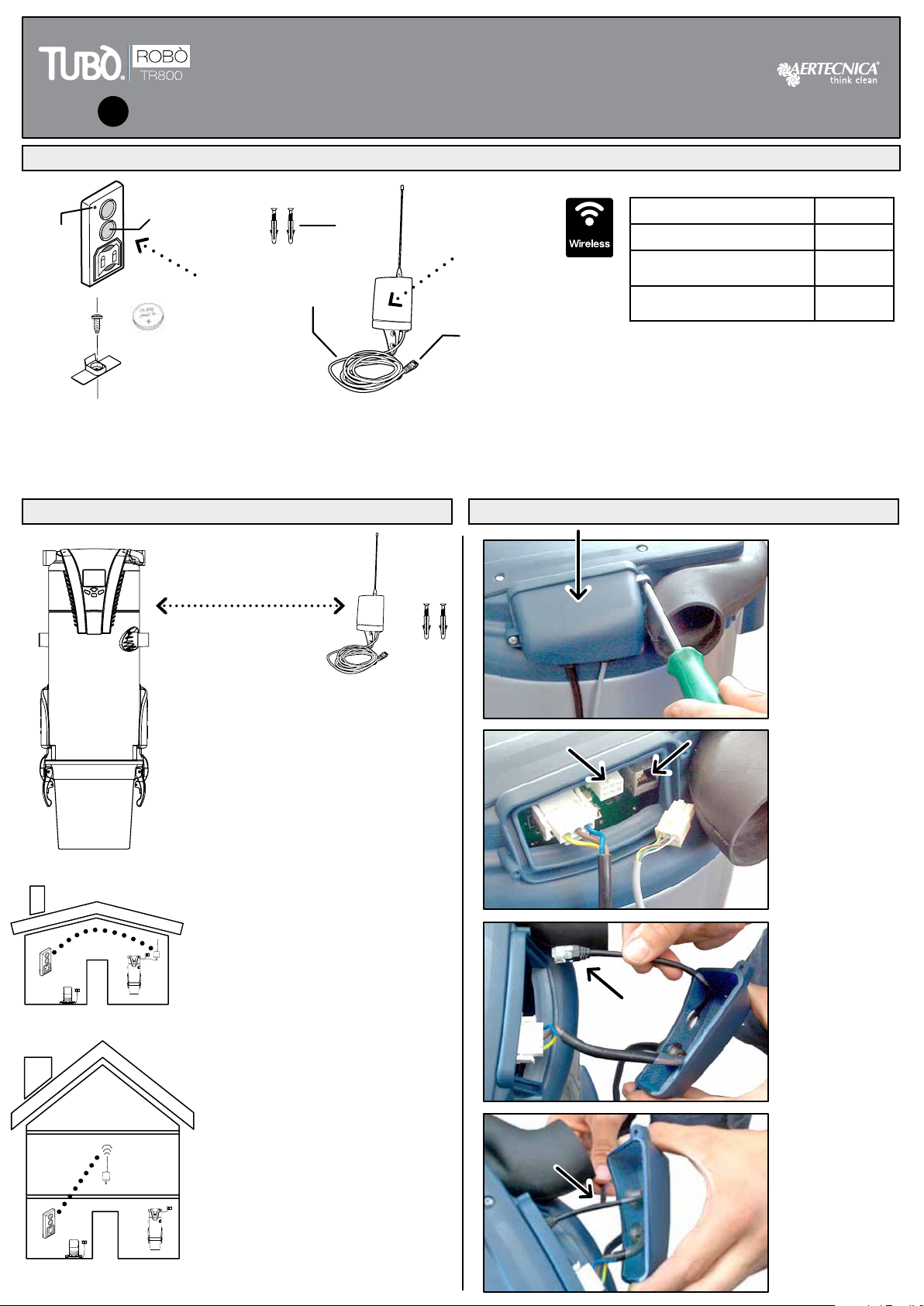
COMPONENTI IN DOTAZIONE
T - trasmettitore wireless per base ROBÒ
A - pulsante di avviamento/arresto
B - led di segnalazione wireless
C - batteria
D - supporto ssaggio trasmettitore con vite
NOTA BENE
In abitazioni composte di più
piani si consiglia di istallare
il ricevitore (R) nel piano
intermedio.
L’apparecchio Ricevitore (R)
non può essere installato in
ambiente esterno all’abitazione
All’interno di un edicio il
raggio di azione tra ricevitore
(R) e trasmettitore (T) è di 15m.
e consente l’attraversamento di
2 solai (S1 - S2)
A
B
T
V
E
C
V
D
1,5 metri
F
R
FREQUENZA DI FUNZIONAMENTO 433,92 Mhz
POTENZA EFFETTIVA RADIO 0,3mW
TIPO DI MODULAZIONE ampiezza
(ON OFF)
ASSORBIMENTO IN
TRASMISSIONE 10mA
CONFORMITÀ ALLA DIRETTIVA 99/05/CE
Il radiocomando è conforme ai requisiti essenziali
ssati dalla Direttiva 99/05/CE.
Sono state applicate le seguenti Norme Tecniche:
EN 60335-1, EN 301489-3, EN 300220-3
E - tubo rilevamento depressione
F - cavo plug per attivazione prese
R - apparecchio Ricevitore wireless
V - viti con tasselli
R
S1
S2
T
T
R
R
1
2
3
4
COLLEGAMENTO WIRELESS
Aprire il carter
del collegamento
elettrico della
centrale.
Scollegare il
connettore linea
micro LM1 ed
estrarre il suo cavo
con il pressacavo.
Inserire il nuovo
cavo wireless
e collegarlo
all’ingresso plug
LM2 dedicato.
Inserire il
pressacavo
nell’apposito foro e
chiudere il carter.
LM1 LM2
1-Posizionare il ricevitore (R) vicino alla centrale
aspirante ad una distanza di circa 1,5 mt.
Fissare il ricevitore (R) alla parete mediante le viti
e i tasselli in dotazione (V)
IT

TRASMETTITORE
T
A
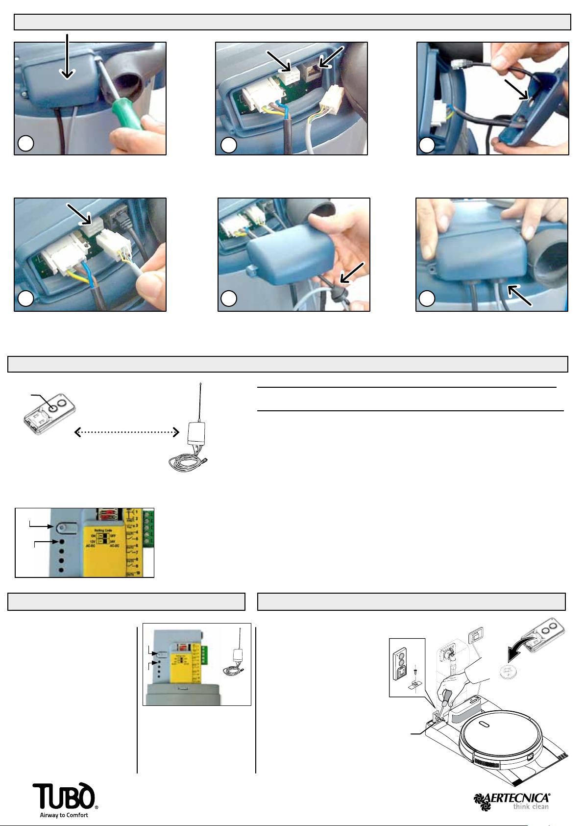
INSTALLAZIONE TRASMETTITORE SU BASE AUTOPULENTE ROBÒ
1 - togliere la batteria (C) interna al
trasmettitore (T)
2 - inserire il trasmettitore (T) nel suo
alloggiamento (G)
3 - bloccare il tramettitore inserendo
il supporto (D)
4 - ssare il supporto (D) alla base
mediante la vite (H).
Il trasmettitore (T) accende e spegne
la centrale aspirante quando ROBÒ si
posiziona sulla base autopulente per
avviare la fase di svuotamento del
suo contenitore polveri.
G
H
T
D
COLLEGAMENTO WIRELESS E LINEA MICRO
Aprire il carter del collegamento elettrico
della centrale aspirante.
Reinserire il connettore della linea micro LM1 nel
suo ingresso dedicato, e introdurre l’altra estremità
del cavo nel foro insieme a quello della linea LM2.
Scollegare il connettore linea micro LM1, togliere
il pressacavo dal foro, slare il cavo.
Inserire nel foro libero il nuovo cavo wireless
e collegarlo all’ingresso plug LM2 dedicato.
Inserire il pressacavo con entrambe le linee LM1
ed LM2 nel foro, chiudere il carter e completare il
collegamento alla linea prese.
Introdurre l’estremità senza ne dentro il
pressacavo dove è già presente il cavo wireless.
LM1 LM2
LM1
PROGRAMMAZIONE TRA TRASMETTITORE E RICEVITORE
H
S
K
SCHEDA
ELETTRONICA
RICEVITORE
1- svitare l’antenna e aprire il ricevitore (R)
2 - premere e tenere premuto il tasto (H) della scheda elettronica (S); si accende per
qualche secondo il led (K)
3 - quando il led (K) si spegne rilasciare il tasto (H); il led comincia una serie di lampeggi
a bassa velocità (1 lampeggio al secondo). Terminati 30 lampeggi, il led (K) rimane acceso.
4 - premere e tenere premuto per qualche secondo il pulsante di avviamento (A) del tubo
da programmare
5 - attendere qualche secondo per la memorizzazione del nuovo segnale; il led (K) si spegne
e si riaccende; il codice è stato memorizzato e il ricevitore rimane in attesa per 5 secondi
di un nuovo codice da memorizzare.
6 - richiudere il ricevitore (R) e riavvitare l’antenna.
La programmazione è terminata. La centrale aspirante si accende ogni volta che si preme il
pulsante (A) del trasmettitore (T).
La centrale aspirante e il ricevitore wireless devono rimanere alimentati.
Il ricevitore wireless è alimentato a 12 volt - non esiste rischio di pericolo elettrico.
R
RICEVITORE
LA PROGRAMMAZIONE TRA TRASMETTITORE E RICEVITORE VIENE GIÀ IMPOSTATA DAL COSTRUTTORE
Via Cerchia di S. Egidio, 760
47521 Cesena (FC) Italy
AERTECNICA S.P.A. Tel. +39 0547 637311
Fax +39 0547 631388
www.aertecnica.com
1- Togliere l’alimentazione 220V alla
centrale aspirante.
2 - Svitare l’antenna e aprire il
ricevitore (R), premere il tasto (H).
3 - Mentre il tasto (H) è premuto,
rialimentare la centrale aspirante.
4 - Il led (K) si accende
5 - Rilasciare il tasto (H).
6 - Allo spegnimento del led (K)
la memoria della scheda è stata
cancellata.
R
H
K
CANCELLAZIONE PROGRAMMI IN MEMORIA
Dopo avere cancellato la
memoria del ricevitore (R) per
riprogrammare il trasmettitore
(T) seguire la procedura
precedente.
T
C
Batteria al litio
da 3V (CR2032)
4
1
5
2
6
3
8TR1061/1
INSTRUCTIONS TUBÒ | ROBÒ CM187TR WIRELESS KIT
WITH START/STOP CENTRAL POWER UNIT
LINES: PERFETTO TXA - TPA - TP / CLASSIC TC
WITH RECEIVER AND TRANSMITTER COMPLETE (SPARE)
INSTALLATION
SUPPLIED COMPONENTS
T - wireless transmitter with ROBÒ base
A - start/stop button
B - wireless signal LED
C - battery
D - transmitter xing support with screw
ATTENTION
If a house has several oors,
we recommend installing the
receiver (R) on the middle oor.
The Receiver (R) cannot be
installed outside the house.
Inside a building, the operating
range between the receiver (R)
and the transmitter (T) is 15m.
and it is capable of intersection
two oors (S1 - S2)
A
B
T
V
E
C
V
D
1,5 meters
F
R
OPERATING FREQUENCY 433.92 Mhz
ACTUAL RADIO POWER 0.3mW
TYPE OF MODULATION amplitude
(ON OFF)
ABSORPTION DURING
TRANSMISSION 10mA
COMPLIANCE WITH DIRECTIVE 99/05/EC
The remote control is compliant with the essential
requirements provided by Directive 99/05/EC.
The following Technical Standards have been applied:
EN 60335-1, EN 301489-3, EN 300220-3
EN
E - depression detection tube
F - plug cable for 12V line activation
R - appliance Wireless receiver
V - screws with plugs
R
S1
S2
T
T
R
R
1
2
3
4
WIRELESS CONNECTION
Open the power
unit’s electric
connection casing
Disconnect
the micro line
connector LM1 and
remove its cable
with the wire press
Insert the new
wireless cable and
connect it to the
dedicated LM2 plug
inlet
Insert the wire
press in the specic
hole and close the
casing.
LM1 LM2
1-Position the receiver (R) near the central vacuum
unit at a distance of roughly 1.5 meters
Fix the receiver (R) to the wall with the screws and
dowels supplied (V)
TRANSMITTER
T
A
TRANSMITTER INSTALLATION WITH ROBÒ SELF CLEANING BASE
1 - removing battery (C) inside transmitter (T)
2 - put the transmitter inside the lodging (G)
3 - inserting support (D) and lock
the transmitter .
4 - x support (D) at the base
through the screw (H).
Transmitter (T) turns on and off the
central vacuum unit when ROBÒ
positions itself on self-cleaning base
to start the emptying phase of its dust
container.
G
H
T
D
WIRELESS AND MICRO LINE CONNECTION
Open the power unit’s electric
connection casing.
Reinsert the LM1 micro line connector into its
dedicated inlet and insert the other cable end into
the hole together with the one from the LM2 line.
Disconnect the micro line connector LM1, remove the
wire press from the hole and remove the cable.
Insert the new wireless cable in the free hole and
connect it to the dedicated LM2 plug inlet.
Insert the wire press with both lines, LM1 and
LM2, into the hole, close the casing and complete
the connection to the socket line.
Insert the endless end into the wire press where
the wireless cable was already inserted.
LM1 LM2
LM1
SETTING BETWEEN TRANSMITTER AND RECEIVER
H
S
K
RECEIVER
ELECTRONIC CARD
1 - check that the connection between the receiver (R) and the central vacuum unit is correct.
2 - unscrew the aerial and open the receiver (R)
3 - remove the electronic card (S).
4 - press the button (H), the LED will switch on (K).
5 - press the start button (A) of the transmitter (T) within 5 seconds
6 - wait a few seconds for the memorisation of the new signal
7 - close the receiver (R) and rescrew the aerial.
The setting has been completed. Whenever the transmitter button (A) is pressed, the
central vacuum unit will switch on.
The central vacuum unit and the wireless receiver must remain connected to the power supply
The wireless receiver is powered by 12 volts so no electrical hazard risk exists.
R
RECEIVER
THE SETTING BETWEEN TRANSMITTER AND THE RECEIVER IS ALREADY SET BY THE MANUFACTURER
Via Cerchia di S. Egidio, 760
47521 Cesena (FC) Italy
AERTECNICA S.P.A. Tel. +39 0547 637311
Fax +39 0547 631388
www.aertecnica.com
1- Disconnect the power line of
the central power unit.
2 - Unscrew the aerial and open the
receiver (R), remove the electronic
card and press the button (H).
3 - While still pressing the button
(H), reconnect the power to the unit.
4 - The LED (K) will switch on.
5 - Release the button (H).
6 - When the LED (K) switches
off, the receiver memory has been
deleted.
R
H
K
DELETING SAVED PROGRAMMES
Once the receiver memory has
been deleted, to reprogramming
the transmitter follow the
previous procedure.
T
C
Lithium battery
3V (CR2032)
4
1
5
2
6
3
Table of contents
Languages:
Other AERTECNICA Remote Control manuals


Popular Remote Control manuals by other brands


Quantum
Quantum FX Instruction booklet

Universal Electronics
Universal Electronics ATLAS XL user guide

SLT
SLT Tactic TT X610 instruction manual

Daikin
Daikin BRC1H71W installation manual

Rasmussen
Rasmussen THR-2R Installation and operating instructions

Mitsubishi Heavy Industries
Mitsubishi Heavy Industries RC-EX3A user manual


