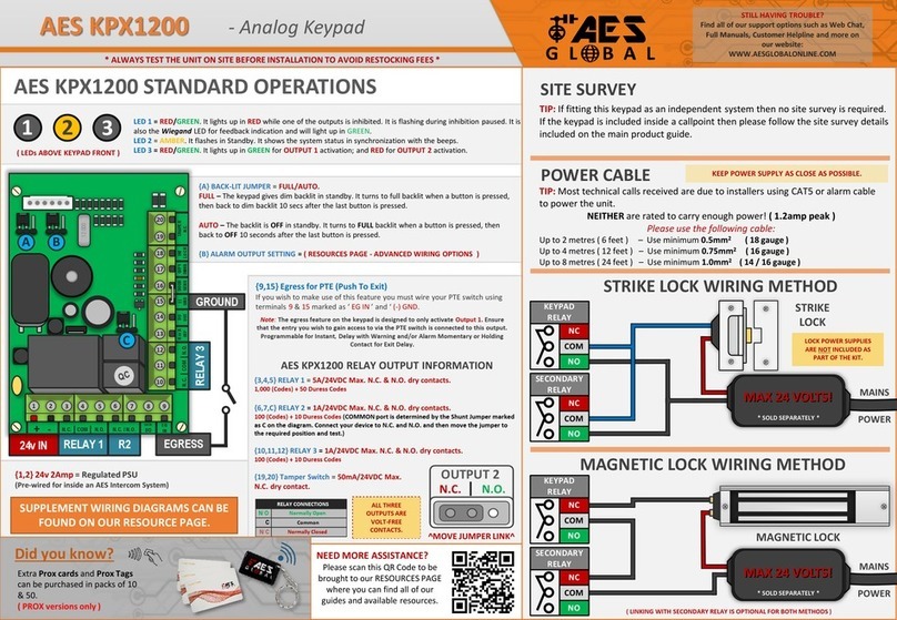
AES global MultiCOM Cellular Series Assembly Instructions

P a g e | 1
Installation & User Instructions
MultiCOM Cellular Range
PROFESSIONAL INSTALL ONLY
Suitable from Firmware Version 3.0.8 (FOTA) (Classic)
Suitable from Firmware Version 2.0.8 (FOTA) (Lite & Mini)
Suitable from Firmware Version 1.0.5 (FOTA) (Modular Multibutton)
The manufacturer cannot legally offer technical support to non-qualified gate
or door installers. End users should employ the services of a professional
install company to commission or support this product!
Tip: Site Survey BEFORE you begin.
See pages 3-4

P a g e | 2
Index
Section
Pages
PHASE 1 –SITE SURVEY
3 –4
Site Survey
4
PHASE 2 –PRODUCT OVERVIEW
5 –21
Overview of Intercoms
6 - 9
More Detail….
10 - 16
PCB Module Overview
Component Sellable Codes
17 –18
19
Technical Specifications
20 - 21
PHASE 3a –SETUP & PROGRAMMING
22 –28
Preparation Before Configuration
23
Inserting the SIM & Power Connections
24
Status LEDs
25
Checking Signal Level and APN
26
Using the AES Pro App
Help/Manager Button
27
28
PHASE 3b –PC PROGRAMMING
29 –35
PC Programming
30 –35
PHASE 4 –USING THE INTERCOM
36–39
Calling a Resident & Using Keypad Codes &
Prox IDs
37
Receiving A Call and Using Caller ID
38
Manager Control of Gate / Door
39
PHASE 5 - INSTALLATION
40 –45
How to Achieve & Maintain IP55 Rating
41
Power and Solar Power
Relay Wiring Examples
Connecting Auxiliary Devices
Auxiliary Device Relay Setup
42
43
44
45
PHASE 6 –AFTERCARE
46 –51
Troubleshooting
47 - 48
Firmware Updates
49
App Updates / Intercom Maintenance /
Environmental Information
50
Documentation Feedback
51
Warranty
52 - 53

P a g e | 3
PHASE 1
Site Survey

P a g e | 4
Important things you Need to Know..
Please read this entire manual before
installing this product.
To be installed by certified and qualified
personnel / gate automation dealer only. Not
for DIY install!
Ensure there is a good 4G signal on site. 4G
units will fall back to 3G service in some
countries.
Set up, on a bench in the workshop
BEFORE going to the site. Program the unit
in the comfort of your workbench and call
technical support should you have
questions.
This product requires a regular voice & SMS
SIM card. Do not use a data-only SIM, as
this will not work in the unit.
To make voice calls on a 4G system
and get optimum service, your SIM and
provider will need to offer VOLTE support
(Voice over LTE) otherwise the unit will be
forced to fall back to 3G or 2G service to
make calls.
Manufacturer warranty does NOT cover
lighting/storm damage. In lightning prone
areas, you MUST fit external surge
protection and a lightning rod to maintain
warranty on this product.
5
6
1
2
3
4

P a g e | 5
PHASE 2
Product Overview

P a g e | 6
Overview of Intercoms(Imperial Design)
Antenna Separate

P a g e | 7
Overview of Intercoms(Pedestal Design)
Antenna Integrated

P a g e | 8
Overview of Intercoms(Flush Design)
Antenna Separate

P a g e | 9
Overview of Intercoms(Modular Pre-Set Design)
Antenna Separate

P a g e | 10
More Detail….
MultiCOM Lite Overview
C
C
C
C
R
V
T
R
V
T
R
V
T
RVT
RVT
RVT
RVT
1
0
1
101
Relay 1
Relay 2
8.000
U
S
B
QUECTEL
QUECTEL
12 3
4 5 6
7 8 9
0
*#
Call status LEDs (for DDA
hearing impaired visitors)
Waterproof Mylar 1.5W speaker (10)
Illuminated keypad (13/14)
Prox reader (12)
Security Screw Access
(Open top screws only)
Press to CALL or
CONFIRM
Illuminated nameplate holder or
information screen. (30 names max) (6)
Download Nameplate template:
www.aesglobalonline.com/downloads
Keypad code
confirm button
Antenna
Connection
Optional Prox Module
&Coil (12)
Cable Entry Hole
Mounting
Holes
Nameplate holder
Illumination
PCB for name
window (6)
Keypad (13/14)
Cellular Module (2)
Note: the numbers in the
brackets (#) relate to the
sellable code table on page 19

P a g e | 11
MultiCOM Lite Modular Overview
C
C
C
C
R
V
T
R
V
T
R
V
T
RVT
RVT
RVT
RVT
1
0
1
101
Relay1
Relay2
8.000
U
S
B
QUECTEL
QUECTEL
Illuminated keypad (13/14)
Press to confirm after
entering door code
Waterproof Mylar 1.5W speaker (10)
Call status LEDs (for
DDA hearing impaired
visitors)
Security Screw Access
(Open top screws only)
Prox reader (12)
Press to CALL or
CONFIRM
Illuminated nameplate holder or
information screen (6)
Download Nameplate template:
www.aesglobalonline.com/downloads
Slave connections for
additional keypad or prox
devices
Keypad (13/14)
Cellular Module (2)
Optional Prox
reader (12)
Antenna connection
LED illumination module (6)
Cable Entry Hole
Mounting
Holes

P a g e | 12
Pedestal Version
C
C
C
C
R
V
T
R
V
T
RVT
RVT
RVT
RVT
QUECTEL
QUECTEL
Microphone (11)
Optional
Keypad (13/14)
Security
Screws
Antenna
Waterproof Mylar
1.5W speaker (10)
Illuminated
name screen (6)
Optional
PROX
Reader (12)
Pedestal
mounting holes
PROX Coil (12)
Cellular Module (2)
Optional keypad
(13/14) & PROX (12)
module
Antenna
Illuminated
name screen (6)
DDA LEDs

P a g e | 13
MultiCOM Classic Overview
HTM1243-101-V00
R
V
T
R
V
T
R
V
T
Slave connections for
additional keypad or prox
devices
Security Screw Access
(Open top screws only)
Keypad (13/14)
Up / down scroll
buttons (8)
Cellular Module (1)
Optional Prox
reader (12)
Waterproof Mylar 1.5W speaker
(10)
Illuminated keypad (13/14)
Press to CALL or
CONFIRM
LCD Display for welcome
message, instructions or to
search residents (5)
Scroll buttons to search
names in directory (8)
Prox reader (12)
Keypad code
confirm button
Antenna connection port
LCD display module (5)
Cable Entry Hole
Mounting
Holes
Call status LEDs (for DDA
hearing impaired visitors)
12 3
4 5 6
7 8 9
0
*#
Scroll for name,
or enter
apartment number
then press CALL

P a g e | 14
MultiCOM Classic Modular Overview
R
V
T
R
V
T
R
V
T
1
0
1
U
S
B
HTM1243-101-V00
Security Screw Access
(Open top screws only)
LCD Display for welcome
message, instructions or to
search residents (5)
Scroll buttons to search
names in directory (8)
Waterproof Mylar 1.5W speaker (10)
Prox reader (12)
Illuminated keypad (13/14)
Press to CALL or
CONFIRM
Press to confirm after
entering door code
Slave connections for
additional keypad or prox
devices
Keypad (13/14)
Up / down scroll
buttons (8)
Cellular Module (1)
Optional Prox
reader (12)
Antenna connection port
LCD display module (5)
Cable Entry Hole
Mounting
Holes
Call status LEDs (for
DDA hearing impaired
visitors)

P a g e | 15
Pedestal Version
R
V
T
R
V
T
R
V
T
U
S
B
HTM1243-101-
V00
Microphone (11)
Optional
Keypad
(13/14)
Security
Screws
Antenna
Waterproof Mylar
1.5W speaker (10)
Scroll
Buttons
(8)
Optional
PROX
Reader (12)
Pedestal
mounting holes
Cellular Module (1)
Optional keypad
(13/14) & PROX (12)
module
Scroll Buttons (8)
Antenna
LCD display
module (5)
LCD
display
module (5)
PROX Coil (12)

P a g e | 16
Modular Multibutton Overview
GND
24
V
GND
24
V
GND
24
V
GND
24
V
GND
24
V
1 2 3 4
5
DC24V
(IN)
DC24V
(OUT)
DC24V
(OUT)
1
2
3
4
5
6
7
8
9
GN
D
1
2
3
4
5
6
7
8
9
GN
D
J
1
J
2
J
3
J
4
G
N
D
GND
24
V
GND
24
V
GND
24
V
GND
24
V
GND
24
V
1 2 3 4
5
DC24V
(IN)
DC24V
(OUT)
DC24V
(OUT)
1
2
3
4
5
6
7
8
9
GN
D
1
2
3
4
5
6
7
8
9
GN
D
J
1
J
2
J
3
J
4
G
N
D
GND
24
V
GND
24
V
GND
24
V
GND
24
V
GND
24
V
1 2 3 4
5
DC24V
(IN)
DC24V
(OUT)
DC24V
(OUT)
1
2
3
4
5
6
7
8
9
GN
D
1
2
3
4
5
6
7
8
9
GN
D
J
1
J
2
J
3
J
4
G
N
D
GND
24
V
GND
24
V
GND
24
V
GND
24
V
GND
24
V
1 2 3 4
5
DC24V
(IN)
DC24V
(OUT)
DC24V
(OUT)
1
2
3
4
5
6
7
8
9
GN
D
1
2
3
4
5
6
7
8
9
GN
D
J
1
J
2
J
3
J
4
G
N
D
RV
T
RV
T
RV
T
RVT
RVT
RVT
RVT
10
1Relay
1
Relay
2
8.00
0
US
B
Call status LEDs (for
DDA hearing impaired
visitors)
Prox reader (12)
Illuminated keypad (13/14)
Illuminated nameplate
holder (will arrive with
applicable button
number inserted for
easy programming)
Resident/Building Call
Button (optional 1-26
button option) (9)
Waterproof Mylar 1.5W speaker (10)
Security Screw Access
(Open top screws only)
Optional Manager / Help Button (9)
Note: Modular can be
purchased in various layout
options and may differ from
shown.
Multibutton PCB (4)
Optional keypad (13/14)
& PROX module (12)
Mounting Holes
Cellular Module (3)
External Power Conditioning
Module (surge protection)
provided with non-pedestal
units.

P a g e | 17
1 2 3 4
ON DI P
SLAVE IN
SLAVE OUT
1 2 3
1 2 3
IN
+ 24V -
OUT
+ 24V -
IN
1 2 3
OUT
1 2 3
COIL
Main Cellular Module (1, 2 or 3) in Detail…
Keypad (13/14) & PROX Module’s (12) in Detail
R
V
T
R
V
T
RVT
RVT
RVT
RVT
QUECTEL
QUECTEL
SLAVE IN
SLAVE OUT
12-24V
OUT 12 3
12-24V
OUT 12 3
Relay 2
DETECT
Gate Position
Limit switch
(optional)
OPEN
Exit Button
PB
To Call
Button
12V = 12v DC
Output 100mA
(backlighting)
DC 24V
Input from
supplied
PSU
Relay 1
Green LED = CPU Status
Blue LED = Signal Status
Red LED = Power
NANO SIM
holder
Female SMA
Antenna
Connection
N/O
COM
N/C
N/O
COM
N/C
USB-B Port
Microphone
Speaker
Slave IN
DATA
DC
Voltage In
Slave OUT
DC Voltage Out
Slave IN
Connectio
ns
DATA Transfer OUT
DATA Transfer IN
IN
DC Voltage In
Slave OUT
Connection
s
12V DC OUT
Push Button
Illumination
Polarity Protected
Master only/Auxiliary
(Baud rate on older units)
Jumper Link

P a g e | 18
Overview of Surge PCB (7)
Overview of Multibutton PCB (4)
*Multibutton Systems Only
Earth Rod MUST be connected for
warranty.
Power Output
NOT USED
24v INPUT –Use provided power supply or hook up to
24v solar system. (DO NOT USE 12v HERE)
12v DC –Battery backup
1 Amp Quick Blow Input Fuse (REPLACEABLE)
Must use a 30 Watt solar panel (minimum) and at least 2 x 10Ah
batteries to supply a regulated 24v
12V | 24 IN | SOL |OUT
GND
24V
GND
24V
GND
24V
GND
24V
GND
24V
1 2 3 4 5 DC24V
(IN)
DC24V
(OUT)
DC24V
(OUT)
1
2
3
4
5
6
7
8
9
GND
1
2
3
4
5
6
7
8
9
GND
J1
J2
J3
J4
GND
Note: Connections will be pre-wired.
PANEL BUTTON
CONFIGURATION
No Jumper = 1-5
J1 = 6-10
J2 = 11-15
J3 = 16-20
J4 = 21-25
Button illumination PCB
(Button numbers are determined
by the position of the jumper link
and button plug. A paper insert will
show the button number position
for convenience.)
10-Way
Connection
Cable
24V DC
IN & OUT

P a g e | 19
Component Sellable Codes
Component
Sellable Code
1
Cellular Module (Classic)
B4G-MULTI-CLASSIC-PCB-US
2
Cellular Module (Lite & Mini)
B4G-MULTI-LITE-PCB-US
3
Cellular Module (Multibutton)
B4G-MULTI-MOD-PCB-US
4
Modular Multibutton PCB
MOD-NP-MB
5
LCD Screen
MULTICOM-LCD-01
6
Illuminated Name Screen
MC-NP
7
Surge PCB
SURGE3
8
Arrow button
BMB1-ARROW
9
Multibutton buttons
ECO-BUTTON
10
Speaker
SPK-ASSM
11
GSM mic
MPA
12
Prox PCB and coil
PROX-PCB-PRIME6
13
Blue prime keypad
PRIME-KP-B-KIT
14
White prime keypad
PRIME-KP-W-KIT

P a g e | 20
Technical Specifications
GENERAL
Front Panel
Portrait Orientation
IBK = 3mm Acrylic on Imperial Design Marine Grade Stainless
Steel BS316 Front Plate
ISK = 1mm Marine Grade Stainless Steel BS316 on Imperial
Design Marine Grade Stainless Steel BS316 Front Plate
FBK = 3mm Acrylic on Flush Design Marine Grade Stainless Steel
BS316 Front Plate
FSK = 1mm Marine Grade Stainless Steel BS316 on Flush Design
Marine Grade Stainless Steel BS316 Front Plate
Landscape Orientation
PED = Pedestal Surface Mount. Powder Coated Marine Grade
Stainless Steel BS316 Front Plates with 3mm Acrylic on Design
Marine Grade Stainless Steel BS316 Modular Plates
Hood Cover (MOD, IBK, PED)
Powder coated Aluminium
Mounting Housing (Backbox)
Marine Grade Stainless Steel BS316
Mounting Type
IBK/ISK = Surface Mounted
FBK/FSK = Flush Mounted
PBK/PSK = Surface Mounted
Call Button
Stainless-steel button with illuminated LED Ring (max. 4
separate buttons)
Power Supply
24V DC (24v dc 2A adaptor included)
Power Consumption
GSM PCB w/Screen & Keypad & Prox
Standby Current: 80mA
Dial Out: 310mA
Max Current: 2A
Solar Power
30Watt Solar Panel (minimum)
2x 12V 10AH Batteries connected in series to provide 24V
output. The power output must be regulated.
Ingress Protection:
IP55
Approvals
FCC, CE
Dimensions
See cataloue
Operating Temperatures
-15 to +55°C / -13 to 131°F
KEYPAD MODULE
Backlighting
Blue / White
Baud Rate
9600
Code Length
4 Digits (fixed)
Confirmation Key
* = Keypad Code confirm | #= Start/End Call
This manual suits for next models
1
Table of contents
Other AES global Keypad manuals
Popular Keypad manuals by other brands
rako
rako WCM-071 instruction manual
AES
AES Keycell Prime 7 4G quick start guide
Fire Burglary Instruments
Fire Burglary Instruments XL560 installation instructions

DELTA DORE
DELTA DORE CLE 8000 TYXAL+ installation guide

Dinsafer
Dinsafer DKPD01A user manual

INIM
INIM Aria Installation and programming manual
urmet domus
urmet domus 1067/022 manual
Bosch
Bosch DS7447V2 Series Specifications

Crestron
Crestron Cameo C2NI-CB Series product manual
Rockwell Automation
Rockwell Automation Allen-Bradley 2711E-NK5 Installation datasheet

B&K
B&K CK2.2 Guide to installation
Fuji Electric
Fuji Electric TP-A1 instruction manual
