Raymarine RMK-10 User manual

© 2016 Raymarine UK Limited
81367-1Document number:
11-2016Date:
English (en-US)
INSTALLATION
INSTRUCTIONS
RMK-10

Trademark and patents notice
Raymarine, Tacktick, Clear Pulse, Truzoom, HSB, SeaTalk, SeaTalkhs, SeaTalkng, Micronet, Raytech,
Gear Up, Marine Shield, Seahawk, Autohelm, Automagic, and Visionality are registered or claimed
trademarks of Raymarine Belgium.
FLIR, DownVision, SideVision, Dragony, Quantum, Instalert, Infrared Everywhere, and The World’s
Sixth Sense are registered or claimed trademarks of FLIR Systems, Inc.
All other trademarks, trade names, or company names referenced herein are used for identication only
and are the property of their respective owners.
This product is protected by patents, design patents, patents pending, or design patents pending.
Fair Use Statement
You may print no more than three copies of this manual for your own use. You may not make any further
copies or distribute or use the manual in any other way including without limitation exploiting the manual
commercially or giving or selling copies to third parties.
English(en-US)
Documentnumber:81367-1
Date:11-2016

Chapter1:Importantinformation
Warning:Productinstallation
andoperation
•Thisproductmustbeinstalledand
operatedinaccordancewiththe
instructionsprovided.Failuretodoso
couldresultinpersonalinjury,damage
toyourvesseland/orpoorproduct
performance.
•Raymarinerecommendscertied
installationbyaRaymarineapproved
installer.Acertiedinstallationqualies
forenhancedproductwarrantybenets.
ContactyourRaymarinedealerfor
furtherdetails,andrefertotheseparate
warrantydocumentpackedwithyour
product.
Warning:Potentialignition
source
ThisproductisNOTapprovedforusein
hazardous/ammableatmospheres.Do
NOTinstallinahazardous/ammable
atmosphere(suchasinanengineroom
ornearfueltanks).
Warning:Productgrounding
Beforeapplyingpowertothisproduct,
ensureithasbeencorrectlygrounded,in
accordancewiththeinstructionsprovided.
Warning:Positiveground
systems
Donotconnectthisunittoasystemwhich
haspositivegrounding.
Warning:Switchoffpower
supply
Ensurethevessel’spowersupplyis
switchedOFFbeforestartingtoinstallthis
product.DoNOTconnectordisconnect
equipmentwiththepowerswitchedon,
unlessinstructedinthisdocument.
Caution:Powersupply
protection
Wheninstallingthisproductensurethe
powersourceisadequatelyprotected
bymeansofasuitably-ratedfuseor
automaticcircuitbreaker.
Wateringress
Wateringressdisclaimer
Althoughthewaterproofratingcapacityofthis
productmeetstheIPX6standard,waterintrusion
andsubsequentequipmentfailuremayoccurifthe
productissubjectedtocommercialhigh-pressure
washing.Raymarinewillnotwarrantproducts
subjectedtohigh-pressurewashing.
Disclaimer
Raymarinedoesnotwarrantthatthisproductis
error-freeorthatitiscompatiblewithproducts
manufacturedbyanypersonorentityotherthan
Raymarine.
Raymarineisnotresponsiblefordamagesorinjuries
causedbyyouruseorinabilitytousetheproduct,
bytheinteractionoftheproductwithproducts
manufacturedbyothers,orbyerrorsininformation
utilizedbytheproductsuppliedbythirdparties.
EMCinstallationguidelines
Raymarineequipmentandaccessoriesconformto
theappropriateElectromagneticCompatibility(EMC)
regulations,tominimizeelectromagneticinterference
betweenequipmentandminimizetheeffectsuch
interferencecouldhaveontheperformanceofyour
system
CorrectinstallationisrequiredtoensurethatEMC
performanceisnotcompromised.
Note:InareasofextremeEMCinterference,
someslightinterferencemaybenoticedonthe
product.Wherethisoccurstheproductandthe
sourceoftheinterferenceshouldbeseparatedby
agreaterdistance.
ForoptimumEMCperformancewerecommend
thatwhereverpossible:
•Raymarineequipmentandcablesconnectedto
itare:
–Atleast1m(3ft)fromanyequipment
transmittingorcablescarryingradiosignalse.g.
VHFradios,cablesandantennas.Inthecase
ofSSBradios,thedistanceshouldbeincreased
to7ft(2m).
–Morethan2m(7ft)fromthepathofaradar
beam.Aradarbeamcannormallybeassumed
tospread20degreesaboveandbelowthe
radiatingelement.
•Theproductissuppliedfromaseparatebattery
fromthatusedforenginestart.Thisisimportantto
preventerraticbehavioranddatalosswhichcan
occuriftheenginestartdoesnothaveaseparate
battery.
•Raymarinespeciedcablesareused.
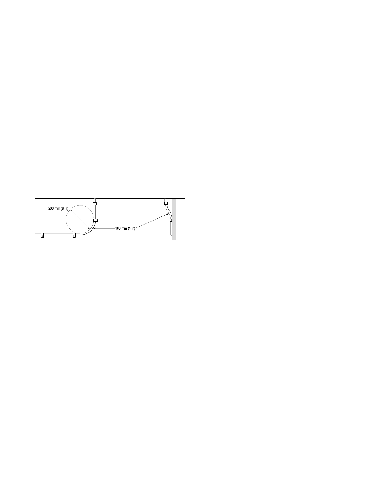
•Cablesarenotcutorextended,unlessdoingsois
detailedintheinstallationmanual.
Importantinformation7

Note:Whereconstraintsontheinstallation
preventanyoftheaboverecommendations,
alwaysensurethemaximumpossibleseparation
betweendifferentitemsofelectricalequipment,to
providethebestconditionsforEMCperformance
throughouttheinstallation
Declaration of conformity
Raymarine UK Ltd. declares that this product is
compliant with the essential requirements of EMC
directive 2004/108/EC.
Product disposal
Dispose of this product in accordance with the
WEEE Directive.
The Waste Electrical and Electronic Equipment
(WEEE) Directive requires the recycling of waste
electrical and electronic equipment.
Warranty registration
It is important that you register your product to
receive full warranty benefits. Your unit package
includes a bar code label indicating the serial number
of the unit. You will need this serial number when
registering your product online. You should retain
the label for future reference.
IMO and SOLAS
The equipment described within this document
is intended for use on leisure marine boats and
workboats NOT covered by International Maritime
Organization (IMO) and Safety of Life at Sea
(SOLAS) Carriage Regulations.
Technical accuracy
To the best of our knowledge, the information in this
document was correct at the time it was produced.
However, Raymarine cannot accept liability for any
inaccuracies or omissions it may contain. In addition,
our policy of continuous product improvement may
change specifications without notice. As a result,
Raymarine cannot accept liability for any differences
between the product and this document.
8

2.1Documentinformation
Thisdocumentcontainsimportantinformation
relatedtotheinstallationofyourRaymarineproduct.
Thedocumentincludesinformationtohelpyou:
•planyourinstallationandensureyouhaveallthe
necessaryequipment;
•installandconnectyourproductaspartofawider
systemofconnectedmarineelectronics;
•troubleshootproblemsandobtaintechnical
supportifrequired.
Product documentation
The following documentation is applicable to your
product:
DescriptionPartnumber
Installationandoperation
instructions
81367
RMK-10Mountingtemplate87283
2.2Productoverview
TheRMK-10isaRemoteKeypadforRaymarine
multifunctiondisplays(MFD).Thekeypadisaclass
1PoE(PowerOverEthernet)deviceandcanbe
poweredeitherusingasuitablenetworkconnection,
thatisprovidingPoE,ordirectlyusingthededicated
Alternatepowerconnector.Thekeypadincludes
aninternalbuzzerthatisusedtorepeatkeypress
beepsandMFDalarms.
Thekeypadcanbemountedinlandscapeorportrait
orientation.
PartnumberDescription
A80438RMK-10—Portraitorientation
WhenorderingA80438onlytheportrait
keypadmatissupplied.
T70293RMK-10—Landscapeorientation
WhenorderingT70293bothorientation
keypadmatsaresupplied.
Compatibility
TheRMK-10iscompatiblewiththefollowing
LightHouse™poweredMFDs.
•aSeries
•cSeries
•eSeries
•gSSeries
•eSSeries
MFDsrequireLightHouse™softwarerelease7or
later.
10
Chapter 2: Document and product information

3.1Installationchecklist
Installationincludesthefollowingactivities:
InstallationTask
1Planyoursystem.
2Obtainallrequiredequipmentandtools.
3Siteallequipment.
4Routeallcables.
5Drillcableandmountingholes.
6Makeallconnectionsintoequipment.
7Secureallequipmentinplace.
8Poweronandtestthesystem.
Schematicdiagram
Aschematicdiagramisanessentialpartofplanning
anyinstallation.Itisalsousefulforanyfuture
additionsormaintenanceofthesystem.The
diagramshouldinclude:
•Locationofallcomponents.
•Connectors,cabletypes,routesandlengths.
3.2Partssupplied
Thepartssuppliedwiththekeypadareshownbelow.
1.RMK-10keypad
2.Landscapekeypadmat
Note:TheLandscapekeypadmatisonly
suppliedwithT70293
3.Portraitkeypadmat(suppliedttedtotheunit)
4.Mountinggasket
5.4xmountingxings
6.Documentationpack
7.Rightangledpowercable2m(6.6ft.)
8.RayNetnetworkcable2m(6.6ft.)
12
Chapter 3: Planning the installation

3.3Softwareupdates
Thesoftwarerunningontheproductcanbeupdated.
•Raymarineperiodicallyreleasessoftwareupdates
toimproveproductperformanceandaddnew
features.
• The software on many products can be updated
using a connected and compatible multifunction
display (MFD).
Important:
•Topreventpotentialsoftware-relatedissueswith
yourproduct,alwaysfollowtherelevantupdate
instructionscarefullyandinthesequence
provided.
•Ifindoubtastothecorrectprocedurefor
updatingyourproductsoftware,refertoyour
dealerorRaymarinetechnicalsupport.
Caution:Installingsoftware
updates
Thesoftwareupdateprocessiscarried
outatyourownrisk.Beforeinitiatingthe
updateprocessensureyouhavebacked
upanyimportantles.
Ensurethattheunithasareliablepower
supplyandthattheupdateprocessisnot
interrupted.
Damagecausedbyincompleteupdates
arenotcoveredbyRaymarinewarranty.
Bydownloadingthesoftwareupdate
package,youagreetotheseterms.
3.4Toolsrequired
Productinstallationrequiresthefollowingtools:
ItemDescriptionQuantity
Powerdrill1
Pozidrivescrewdriver1
Drillbitofappropriatesize*1
Adhesivetape1
Note:*Theappropriatedrillbitsizeisdependent
onthethicknessandmaterialofthemounting
surface.
Planningtheinstallation13

3.5Generallocationrequirements
Importantconsiderationswhenchoosingasuitable
locationforyourproduct.
Thisproductissuitableformountingaboveorbelow
decks.
Theproductshouldbemountedwhereitwillbe:
•protectedfromphysicaldamageandexcessive
vibration.
•wellventilatedandawayfromheatsources.
•awayfromanypotentialignitionsourcesuchasan
engineroom,nearfueltanksoragaslocker.
Whenchoosingalocationfortheproduct,
considerthefollowingpointstoensurereliableand
trouble-freeoperation:
•Access—theremustbesufcientspaceto
enablecableconnectionstotheproduct,avoiding
tightbendsinthecable.
•Diagnostics—theproductmustbemountedin
alocationwherethediagnosticsLEDiseasily
visible.
Note:Notallproductsincludeadiagnostics
LED.RefertotheChapter7Systemchecks
andtroubleshootingformoreinformation.
•Electricalinterference—theproductshouldbe
mountedfarenoughawayfromanyequipment
thatmaycauseinterferencesuchasmotors,
generatorsandradiotransmitters/receivers.
•Magneticcompass—refertotheCompass
safedistancesectioninthisdocumentforadvice
onmaintainingasuitabledistancebetweenthis
productandanycompassesonyourvessel.
•Power—tokeepcablerunstoaminimum,the
productmustbelocatedascloseaspossibleto
thevessel’sdcpowersupply.
•Mountingsurface—ensuretheproductis
adequatelysupportedonasecuresurface.Refer
totheweightinformationprovidedintheTechnical
specicationforthisproductandensurethatthe
intendedmountingsurfaceissuitableforbearing
theproductweight.DoNOTmountunitsorcut
holesinplaceswhichmaydamagethestructure
ofthevessel.
Productdimensions
3.6Warningsandcautions
Important:Beforeproceeding,ensurethatyou
havereadandunderstoodthewarningsand
cautionsprovidedintheChapter1Important
informationsectionofthisdocument.
14

4.1Generalcablingguidance
Cabletypesandlength
Itisimportanttousecablesoftheappropriatetype
andlength
•Unlessotherwisestateduseonlystandardcables
ofthecorrecttype,suppliedbyRaymarine.
•Ensurethatanynon-Raymarinecablesareofthe
correctqualityandgauge.Forexample,longer
powercablerunsmayrequirelargerwiregauges
tominimizevoltagedropalongtherun.
Routingcables
Cablesmustberoutedcorrectly,tomaximize
performanceandprolongcablelife.
•DoNOTbendcablesexcessively.Wherever
possible,ensureaminimumbenddiameterof200
mm(8in)/minimumbendradiusof100mm(4in).
•Protectallcablesfromphysicaldamageand
exposuretoheat.Usetrunkingorconduitwhere
possible.DoNOTruncablesthroughbilgesor
doorways,orclosetomovingorhotobjects.
•Securecablesinplaceusingtie-wrapsorlacing
twine.Coilanyextracableandtieitoutoftheway.
•Whereacablepassesthroughanexposed
bulkheadordeckhead,useasuitablewatertight
feed-through.
•DoNOTruncablesneartoenginesoruorescent
lights.
Alwaysroutedatacablesasfarawayaspossible
from:
•otherequipmentandcables,
•highcurrentcarryingACandDCpowerlines,
•antennae.
Strain relief
Ensure adequate strain relief is provided. Protect
connectors from strain and ensure they will not pull
out under extreme sea conditions.
Cable shielding
Ensure that all data cables are properly shielded
that the cable shielding is intact (e.g. hasn’t been
scraped off by being squeezed through a tight area).
separatelytothecables(i.e.notpre-tted),you
musttthesuppliedferrites,usingthesupplied
instructions.
•Ifaferritehastoberemovedforanypurpose(e.g.
installationormaintenance),itmustbereplacedin
theoriginalpositionbeforetheproductisused.
•Useonlyferritesofthecorrecttype,suppliedby
Raymarineoritsauthorizeddealers.
•Whereaninstallationrequiresmultipleferritesto
beaddedtoacable,additionalcableclipsshould
beusedtopreventstressontheconnectorsdue
totheextraweightofthecable.
16
Chapter 4: Cables and connections
Raymarine cables may be pre-fitted or supplied
with suppression ferrites. These are important for
correct EMC performance. If ferrites are supplied
Suppression ferrites

4.2Connectionsoverview
1.Alternatepowerconnector
2.Network/PoEconnector
Thealternatepowerconnectorisrequiredwhen
connectingtoanetworkwhichdoesnotsupport
PoweroverEthernetPoE.Thealternatepower
connectormustbeconnecteddirectlytoapower
supply.
Note:Donotconnectthealternatepower
connectortoaSeaT alkngnetwork.
Note:Onlyuseonepowersource.Thereisno
needtoconnectthealternatepowerconnector
whenthekeypadisbeingsuppliedPoE.
4.3Alternatepowerconnection
WhenthekeypadisnotsuppliedPowerover
Ethernet(PoE)thenthealternatepowerconnection
shouldbeconnecteddirectlytoa12Vdcor24Vdc
powersupply.
1.Keypad
2.Rightangledpowercable
3.Blacknegativewire
4.Ground/shieldwire
5.Redpositivewire
Warning:Productgrounding
Beforeapplyingpowertothisproduct,
ensureithasbeencorrectlygrounded,in
accordancewiththeinstructionsprovided.
Grounding—Dedicateddrainwire
Thepowercablesuppliedwiththisproductincludes
adedicatedshield(drain)wireforconnectiontoa
vessel'sRFgroundpoint.
ItisimportantthataneffectiveRFgroundis
connectedtothesystem.Asinglegroundpoint
shouldbeusedforallequipment.Theunitcanbe
groundedbyconnectingtheshield(drain)wireof
thepowercabletothevessel'sRFgroundpoint.
OnvesselswithoutanRFgroundsystemtheshield
(drain)wireshouldbeconnecteddirectlytothe
negativebatteryterminal.
Thedcpowersystemshouldbeeither:
•Negativegrounded,withthenegativebattery
terminalconnectedtothevessel'sground.
•Floating,withneitherbatteryterminalconnected
tothevessel'sground
Warning:Positiveground
systems
Donotconnectthisunittoasystemwhich
haspositivegrounding.
Cablesandconnections17

4.4Keypadconnections
Thekeypadcanbeconnecteddirectlytoa
multifunctiondisplay’s(MFDs)networkconnector
orviaanetworkswitch.Multiplekeypadscanbe
connectedtoasystem.Eachkeypadcanbeusedto
controlmultipleMFDs.Ifthenetworkisnotproviding
PoweroverEthernet(PoE)thenthekeypadmustbe
poweredusingtheAlternatepowerconnector.
Note:WhenconnectingthekeypadtoagSSeries
MFD,ensurethatthesuppliedRayNetcableis
connectedwiththesuppressionferritettedonthe
endofthecableclosesttotheMFD.
DirectMFDconnectionwithPoE
1.gSSeries(MFDprovidingPoE)
2.RMKkeypad
3.RayNetnetworkcable(withsuppressionferrite
tted)
DirectMFDconnectionwithoutPoE
1.MFD
2.RayNetnetworkcable
3.RMKkeypad
4.Rightangledpowercable(Connectedtothe
alternatepowerconnector.)
DirectMFDconnectionwithPoEinjector
1.MFD
2.RMKkeypad
3.RayNettoRJ45networkcable(A62360,A80151
orA80159)
4.PoEinjectorpowersupply(12/24Vdc)
5.PoEinjector(R32141)
NetworkconnectionviaMFDwithPoE
1.gSSeries(MFDprovidingPoE)
2.RMKkeypad
3.RayNetnetworkcable(withsuppressionferrite
tted)
4.NetworkedMFDs
Note:Thekeypadcanbeusedtocontrol
networkedMFDsevenwhentheMFDitis
connectedtoisswitchedoff,aslongastheMFD
stillhaspowersuppliedtoit.
Networkconnectionvianetworkswitch
IntheillustrationaboveaPoEinjectorcouldbeused
insteadoftheAlternatepowerconnection.
1.Networkswitch
2.RMKkeypad
18

3.Rightangledpowercable(Connectedtothe
alternatepowerconnector.)
4.NetworkedMFDs
Note:Onceconnectedthekeypadmustbepaired
witheachMFDyouwanttocontrolwiththekeypad.
Cablesandconnections19

5.1Removingthekeypadmat
Togainaccesstothemountingholelocations,the
keypadmatmustberemoved.
TipT ohelppreventscratchingtheproduct,coverthe
tipofyourscrewdriverbladewithasmallpieceof
insulationtape.
1.Usingathin,atbladedscrewdriverinsertthetip
ofthescrewdriverintothegapbetweentheedge
ofthekeypadmatandthekeypadhousing,ata
locationbetweenlockingtabs.
2.Gentlyleverthekeypadmatawayfromthe
keypadtoreleasethekeypadmat.
Takecarenottobendthekeypadmatduring
removal.
5.2Flushmountingthekeypad
Flushmountingprovidesasleekinstallationwhere
theproductanddashareush,withonlythebuttons
andRotarycontrollerprotrudingfromthedash.
Flushmountingrequiresthemountingsurfacetobe
rebated.
1.Checktheselectedlocationfortheunit.Aclear,
atareawithsuitableclearancebehindthepanel
isrequired.
2.Beforemodifyingthemountingsurface,refer
tothedimensionssuppliedinthisdocumentto
ensurethereisenoughspacefortheunitandall
cables.
3.Fixthesuppliedmountingtemplatetothe
selectedlocation,usingmaskingorselfadhesive
tape.
4.Drill4holesasindicatedonthemounting
templatetoacceptthexings.
5.Usingasuitableholesaw(thesizeandposition
isindicatedonthetemplate),makeaholeineach
cornerofthecut-outarea.
6.Usingasuitablesaw,cutalongtheinsideedge
ofthecut-outline.
7.UsingaRouter,followtheFlushmountrebate
line,tocutoutarebatetothespeciedrebate
depth,asindicatedonthetemplate.
8.Ensurethattheunittsintotheremovedarea
andthenremoveroughedges.
9.Placethesuppliedgasketontotherearofthe
keypad,ensuringthemountingholesarealigned.
10.Connecttherelevantcablestotheunit.
11.Placethekeypadintotherebateandsecure
usingthexingsprovided.
Note:Theappropriatetighteningtorqueanddrill
bitsizetousedependsonthethicknessofthe
mountingsurfaceandthetypeofmaterialitis
madefrom.
Note:Thesuppliedgasketprovidesaseal
betweentheunitandasuitablyatandstiff
mountingsurfaceorbinnacle.Thegasketshould
beusedinallinstallations.Itmayalsobe
necessarytouseamarine-gradesealantifthe
mountingsurfaceorbinnacleisnotentirelyatand
stifforhasaroughsurfacenish.
22
Chapter 5: Mounting

5.3Surfacemountingthekeypad
Surfacemountingprovidesauniforminstallation
wheretheproductsprotrude,usuallybythethickness
ofthebezel,fromthemountingsurface.
1.Checktheselectedlocationfortheunit.Aclear,
atareawithsuitableclearancebehindthepanel
isrequired.
2.Beforemodifyingthemountingsurface,refer
tothedimensionssuppliedinthisdocumentto
ensurethereisenoughspacefortheunitandall
cables.
3.Fixthesuppliedmountingtemplatetothe
selectedlocation,usingmaskingorselfadhesive
tape.
4.Drill4holesasindicatedonthemounting
templatetoacceptthexings.
5.Usingasuitableholesaw,makeaholeineach
cornerofthecut-outarea.
6.Usingasuitablesaw,cutalongtheinsideedge
ofthecut-outline.
7.Ensurethattheunittsintotheremovedarea
andthenremoveroughedges.
8.Placethesuppliedgasketontotherearofthe
keypad,ensuringthemountingholesarealigned.
9.Connecttherelevantcablestotheunit.
10.Secureusingthexingsprovided.
Note:Theappropriatetighteningtorqueanddrill
bitsizetousedependsonthethicknessofthe
mountingsurfaceandthetypeofmaterialitis
madefrom.
Note:Thesuppliedgasketprovidesaseal
betweentheunitandasuitablyatandstiff
mountingsurfaceorbinnacle.Thegasketshould
beusedinallinstallations.Itmayalsobe
necessarytouseamarine-gradesealantifthe
mountingsurfaceorbinnacleisnotentirelyatand
stifforhasaroughsurfacenish.
5.4Fittingthekeypadmat
Yourkeypadcanbeinstalledinportraitorlandscape
orientation.keypadmatsareavailableforeach
orientation.
•Youshouldtthekeypadmatthatmatchesyour
chosenmountingorientation.
•Youshouldonlytthekeypadmataftertheunit
hasbeensecuredtothemountingsurface.
1.Ensurethekeypadmatisorientatedcorrectly.
2.Slidethekeypadmat’sshorteredge,withthe2
lockingtabs,intotheendofthekeypadthathas
2notchestoacceptthetabs.
3.Closetheoppositeendofthekeypadmatinto
thekeypad,ensuringthatthetabslidesintothe
notchprovided,pushallofthetabsonthelonger
sidesintotheirnotches(youshouldhearaclick
aseachtabengages).
Mounting23

1.Home—presstoreturntotheHomescreen.
2.Menu—accessesmenus.Pressagaintoclose
menus.
3.UniController—providesarotarycontroland
ajoystickthatincludesanOKpushbuttonfor
usingmenusandapplications.
4.Back—presstoreturntoapreviousmenuor
dialoglevel.
5.-(Minus/Negativesymbol)—presstorangeout.
6.+(Plus/Positivesymbol)—presstorangein.
7.Active—presstoswitchtheactivepane,or
toswitchtheactivemultifunctiondisplay(in
multipledisplaysystems).
8.Waypoint/MOB—pressandreleaseto
accessthewaypointoptions.Pressagainto
placeawaypoint.Pressandholdtoplacea
ManOverboard(MOB)markeratyourcurrent
position.
9.Standby(Auto)—presstodisengage
integratedautopilot,pressandholdtoactivate
Automodeonintegratedautopilot.
10.Power—seetablebelow:
Congura-
tion
Display
State
Momentary
press
Pressand
hold
Off/Standby*Poweron—
1
Multifunction
displayOnOpen
Shortcuts
page
Poweroff
/putinto
Standby
Alldisplays
Offorin
Standby
*Poweron
alldisplays
—
Alldisplays
On
Open
Shortcuts
pageon
activedisplay
Powerdown
alldisplays
Multiple
multifunction
displays
1Display
Onand1
displayOff
orinStandby
Open
Shortcuts
pageon
activedisplay
Powerdown
activedisplay
Note:Inamultipledisplayconguration,
wheredisplaysareindifferentstates,displays
thatareturnedoffcanonlybeturnedonusing
thePowerbuttononthedisplay.
11.DirectionofJoystickUp.
Chapter 6: Operation
6.1 Keypad controls
Connecting the keypad allows you to control your
multifunction display remotely.
Note:*OnlyapplicabletoeSandgSSeries
displays.aSeries,cSeriesandeSeries
displayscannotbepoweredonusingthe
keypad.

6.2Pairingthekeypad
EachkeypadcanbepairedwithmultipleMFDsand
multiplekeypadscanbeconnectedtothesame
system.
WiththekeypadconnectedtotheMFD:
1.SelectExternalKeypadfromtheExternal
Devicesmenu:homescreen>Set-up>System
Settings>ExternalDevices>External
Keypad.
2.SelectPairKeypad.
3.Pressanybuttonontheexternalkeypad.
4.Fromthepop-upmessageselecttheorientation
ofthekeypad.
Eitherlandscapeorportraitorientationsare
available.
Thekeypadisnowpaired.
Switchingtheactivepaneordisplay
usingthekeypad
TheActivebuttonisusedtoswitchtheactivepane
onamultiapplicationpageand/ortoswitchthe
activedisplay.
Withmultipledisplaysconnectedand/oramultiple
applicationpagedisplayed:
Cyclesequence
1.PresstheActivebuttontoenterswitchmode.
2.UsetheRotarycontroltocyclethroughthe
availablepanesand/ordisplays.
Thekeypadwillcyclethroughdisplaysinthe
orderinwhichtheywerepaired.Onmulti
applicationpagesthe+and-buttonscanbe
usedtoswitchtheactiveapplicationbetweenfull
andsplitscreen.
3.PresstheBackbuttonortheActivebuttonto
exitswitchmode.
Unpairingthekeypad
Thekeypadcanbeunpairedfromanindividual
display.
1.SelectExternalKeypadfromtheExternal
Devicesmenu:homescreen>Set-up>System
Settings>ExternalDevices>External
Keypad.
2.SelectClearPairings.
3.SelectYestounpairthekeypadwiththedisplay.
Unpairingfromalldisplays
Thekeypadcanbeunpairedfromalldisplays
followingthestepsbelow.
1.PressandholdtheRangeInandRangeOut
buttonssimultaneouslyforapproximately6
seconds.
Thekeypadwillsoundatriplebeeptosignifyitis
nowunpaired.
Determiningtheactivedisplay
Youcandeterminewhichdisplayiscurrentlyactive.
1.PresstheActivebutton.
TheActivepop-upisdisplayedonthescreenor
panethatisactive.
2.PresstheActivebuttonagaintoclosetheActive
pop-up.
Theactivedisplayremainsthesame.
Operation27

7.1Keypadstatus
ThekeypadisbacklitwithLEDs.TheLEDsareused
toidentifythestatusofthekeypad.
Status
UniController
LEDringKeypadbacklight
Keypadpowered
offornotpaired
OffOff
Keypadispowered
onandpaired
OnOn
MFDisin
PowerSavemode
FlashingOff
TheLEDandkeypadbacklightbrightnesswill
changetomatchthepairedMFDbrightness.
7.2PoEtroubleshooting
Ifyouareexperiencingconnectionissueswith
theremotekeypadwhenpoweringthedevicevia
PoE,considerusingthekeypad’sdedicatedpower
connectortosupplythepowertothedevice.
Possiblecausesforconnectionissuesare:
•Loworinconsistentvoltageatthepowersupply
totheMFD.
•Inadequatepowerordatacabling.
•IfmultipledevicesarepoweredviaPoEfromthe
MFD,thepowerallocationforthePoEdevices
maybetoohigh,eitherbecausetherearetoo
manydeviceconnected,orthetotalpower
consumptionexceedsthesupportedallocation.
RefertothePoweroverEthernet(PoE)topicin
theMFD’sInstallationinstructionsdocumentfor
moreinformationonthePoEpowerallocation.
30
Chapter 7: System checks and troubleshooting

7.3Poweruptroubleshooting
Problemsatpowerupandtheirpossiblecausesandsolutionsaredescribedhere.
Productdoesnotturnonorkeepsturningoff
PossiblecausesPossiblesolutions
Blownfuse/trippedbreaker1.Checkconditionofrelevantfusesandbreakersandconnections,replace
ifnecessary(RefertotheT echnicalSpecicationsectionofyourproduct’s
installationinstructionsforfuseratings.)
2.Iffusekeepsblowingcheckforcabledamage,brokenconnectorpinsor
incorrectwiring.
Poor/damaged/insecurepowersupply
cable/connections
1.Checkthatthepowercableconnectorisfullyinsertedintotheunitandlockedin
position.
2.Checkthepowersupplycableandconnectorsforsignsofdamageorcorrosion,
replaceifnecessary.
3.Withtheunitturnedon,tryexingthepowercableneartothedisplayconnector
toseeifthiscausestheunittore-boot/loosepower,replaceifnecessary.
4.Checkthevessel’sbatteryvoltage,theconditionofthebatteryterminalsand
powersupplycables,ensuringconnectionsaresecure,cleanandfreefrom
corrosion,replaceifnecessary.
5.Withtheproductunderload,usingamulti-meter,checkforhighvoltagedrop
acrossallconnectors/fusesetc,replaceifnecessary.
IncorrectpowerconnectionThepowersupplymaybewiredincorrectly,ensuretheinstallationinstructionshave
beenfollowed.
PowersourceinsufcientWiththeproductunderload,usingamulti-meter,checkthepowersupplyvoltageas
closetotheunitaspossibletoestablishactualvoltagewhenthecurrentisowing.
(RefertotheT echnicalSpecicationsectionofyourproduct’sinstallationinstructions
forpowersupplyrequirements.)
Productwillnotbootup(re-bootloop)
PossiblecausesPossiblesolutions
PowersupplyandconnectionSeepossiblesolutionsfrom‘Productsdoesnotturnonorkeepsturningoff’above.
Softwarecorruption1.Intheunlikelyeventthattheproductssoftwarehasbecomecorruptedpleasetry
re-ashingthelatestsoftwarefromtheRaymarinewebsite.
2.Ondisplayproducts,asalastresort,youcantrytoperforma‘PoweronReset’,
howeverthiswilldeleteallsettings/presetsanduserdata(suchaswaypoints
andtracks)andreverttheunitbacktofactorydefaults.
Systemchecksandtroubleshooting31

8.1Serviceandmaintenance
Thisproductcontainsnouserserviceable
components.Pleasereferallmaintenance
andrepairtoauthorizedRaymarinedealers.
Unauthorizedrepairmayaffectyourwarranty.
8.2Routineequipmentchecks
Raymarinestronglyrecommendsthatyoucomplete
anumberofroutinecheckstoensurethecorrectand
reliableoperationofyourequipment.
Completethefollowingchecksonaregularbasis:
•Examineallcablesforsignsofdamageorwear
andtear.
•Checkthatallcablesaresecurelyconnected.
34
Chapter 8: Maintenance
8.3Productcleaning
Bestcleaningpractices.
Whencleaningproducts:
•Lightlyrinseorushwithclean,coolfreshwater.
•Ifyourproducthasadisplayscreen,doNOTwipe
thescreenwithadrycloth,asthiscouldscratch
thescreencoating.
•DoNOTuse:abrasive,acidic,ammonia,solvent
ofchemicalbasedcleaningproducts.
•DoNOTuseajetwash.

9.1Technicalspecication
Powerspecication
PoEclassClass1
Nominalsupply
voltage
•PoE:48Vdc
•Alternatepower:12V/24Vdc
Operating
voltagerange
•PoE:44Vto57Vdc
•Alternatepower:9Vto32Vdc
Power
consumption
4WMaxwithfullkeypadillumination
Environmentalspecication
Operating
temperature
-25ºCto+55ºC(-13ºFto131ºF)
Storage
temperature
-30ºCto+70ºC(-22ºFto158ºF)
RelativehumidityMaximum93%
WaterproofratingIPx6&IPx7
Wiredconnections
Network/PoE1xRayNet10/100Mb/sconnector
Alternatepower1xPowerconnector(SeaTalkng®style
connector)
9.2Compliance
Theproducthasbeentestedtotherelevantsections
ofthestandardslistedbelow.
Ethernet/PoE•IEEE802.3
•IEEE802.3af(PoE)
EMC•EN60945
38
Chapter 9: Technical speci ication
Other manuals for RMK-10
1
Table of contents
Other Raymarine Keypad manuals
Popular Keypad manuals by other brands

General Lock
General Lock L100 Series installation instructions

Conlan
Conlan CT1000 user manual

Rosewill
Rosewill RT-CY687B user manual

Mottura
Mottura Nucleo REPLAY MY KEY Code Setting Instructions

Digilock
Digilock Next lock Sola quick start guide

Automatic Technology
Automatic Technology KPX-7V2 Quick setup guide