AES global SnapCOM PRIME Cellular Series Assembly Instructions

P a g e | 1
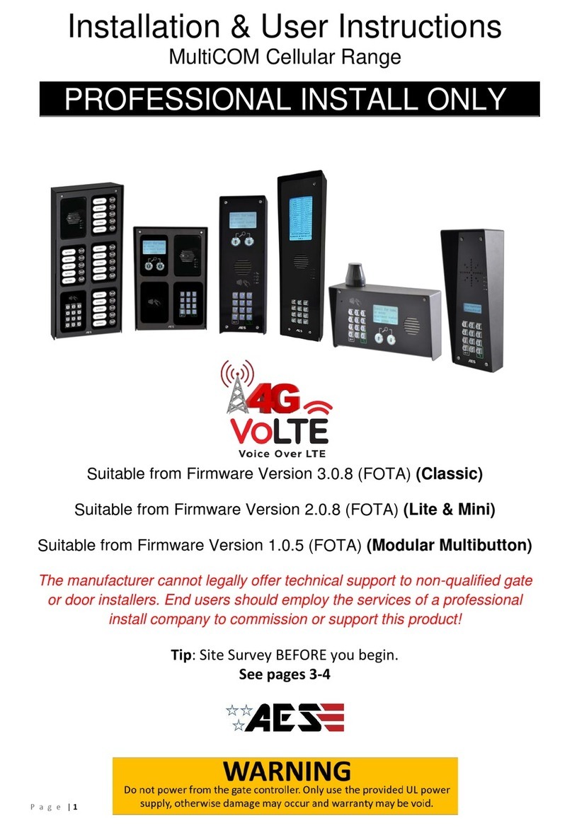
Installation & User Instructions
SnapCOM PRIME Cellular Range
PROFESSIONAL INSTALL ONLY
Suitable from Firmware Version 2.1.4 (FOTA)
The manufacturer cannot legally offer technical support to non-qualified gate
or door installers. End users should employ the services of a professional
install company to commission or support this product!
Tip: Site Survey BEFORE you begin.
See pages 3-4

P a g e | 2
Index
Section
Pages
PHASE 1 –SITE SURVEY
3 - 4
Site Survey
4
PHASE 2 –PRODUCT OVERVIEW
5 - 15
Overview of Intercoms
6 - 7
More Detail….
8 - 10
PCB Module Overview
11 - 12
Component Sellable Codes
Technical Specifications
13
14 - 15
PHASE 3 –SETUP & PROGRAMMING
16 - 22
Preparation Before Configuration
17
Inserting the SIM & Power Connections
18
Status LEDs
19
Checking Signal Level and APN
20-21
Using the AES Pro App
22
PHASE 4 –USING THE INTERCOM
23 –26
Calling a Resident & Using Keypad Codes &
Prox IDs
24
Receiving A Call and Using Caller ID
25
Manager Control of Gate / Door
26
PHASE 5 - INSTALLATION
27 - 32
How to Achieve & Maintain IP55 Rating
28
Power & Solar Power
29
Relay Wiring Examples
30
Connecting Auxiliary Devices
Auxiliary Device Relay Setup
31
32
PHASE 6 –AFTERCARE
33 –39
Troubleshooting
34 –36
Firmware Updates
37
App Updates / Intercom Maintenance / Extra
Resources / Environmental Information
38
Documentation Feedback
39
Warranty
40-41

P a g e | 3
PHASE 1
Site Survey

P a g e | 4
Important things you Need to Know..
Please read this entire manual before installing
this product.
To be installed by certified and qualified
personnel / gate automation dealer only.
Not for DIY install!
Ensure there is a good 4G signal on site. 4G
units will fall back to 3G service in some
countries.
Set up, on a bench in the workshop
BEFORE going to the site. Program the
unit in the comfort of your workbench
and call technical support should you
have questions.
This product requires a regular voice, SMS and
data SIM card with an MMS plan. Do not use a
data-only SIM, as this will not work in the
unit.
To make voice calls on a 4G system
and get optimum service, your SIM and provider
will need to offer VOLTE support (Voice over
LTE) otherwise the unit will be forced to fall back
to 3G or 2G service to make calls.
Manufacturer warranty does NOT cover
lighting/storm damage. In lightning prone
areas, you MUST fit external surge
protection and a lightning rod to maintain
warranty on this product.
5
6
1
2
3
4

P a g e | 5
PHASE 2
Product Overview

P a g e | 6
Overview of Intercoms(Imperial Design)
Antenna Separate
Overview of Intercoms(Architectural Design)
Antenna Separate
Overview of Intercoms(Pedestal Design)
Antenna Integrated

P a g e | 7
Overview of Intercoms(Flush Design)
Antenna Separate

P a g e | 8
More Detail….
SnapCOM Keypad Version Overview
Note: the numbers in the
brackets (#) relate to the
sellable code table on
page 13.
8GB
SD CARD
USB
Relay 2
Relay 1
FCON
SCA
1500
6.3V
FCON
SCA
1500
6.3V
220
50V
RVT
FCON
SCA
1500
6.3V
101
QUECTEL
QUECTEL
12 3
4 5 6
7 8 9
0
*#
SnapCOM Cellular Module
(2)
Security screw
access
Waterproof Mylar
1.5W speaker (10)
DDA
LEDs
Optional
illuminated
keypad (15/16)
Illuminated IP67
push button (7/8)
Microphone (11)
Mounting holes
Cable entry hole
Optional Keypad (15/16)
Illuminated IP67
push button (7/8)
LED Light Strip
PCB (3)
Camera (4)
LED Light Strip
PCB (3)
Camera (4)

P a g e | 9
SnapCOM Non-Keypad Version Overview
SnapCOM Cellular
Module (2)
Illuminated IP67
push button (7/8)
Illuminated IP67
push button (7/8)
Camera (4)
LED Light Strip PCB (3)
Cable entry hole
Mounting holes
Backlighting PCB (13)
Camera (4)
LED Light
Strip PCB (3)
Waterproof Mylar
1.5W speaker (10)
External Power
Conditioning Module
(surge protection) provided
with non-pedestal units.

P a g e | 10
SnapCOM Pedestal Overview
Without PCB (Printed Circuit Board) With PCB (Printed Circuit Board)
8GB
SDC ARD
USB
Relay 2
Relay 1
FCON
SCA
1500
6.3V
FCON
SCA
1500
6.3V
220
50V
RVT
FCON
SCA
1500
6.3V
101
QUECTEL
QUECTEL
12 3
4 5 6
7 8 9
0
*#
DDA Sleeve
Waterproof Mylar 1.5W
speaker (10)
Illuminated IP67
push button (7/8)
LED PCB (3)
Camera (4)
SnapCOM Cellular
Module (2)
Illuminated IP67
push button (7/8)
Camera (4)
LED Light Strip
PCB (3)
Keypad
(15/16)
Cam Lock (17)
Surge PCB (1)

P a g e | 11
Main Cellular Module (2) in Detail…
Keypad Module (15/16) in Detail
8GB
SD CARD
USB
Relay 2Relay 1
FCO N
SCA
1500
6.3V
FCO N
SCA
1500
6.3V
220
50V
RVT
FCON
SCA
1500
6.3V
101
220
QUECTEL
QUECTEL
SLAVE IN
SLAVE OUT
12-24V
OUT 12 3
12-24V
OUT 12 3
Relay 2
DETECT
Gate Position
Limit switch
(optional)
OPEN
Exit Button
DC 24V
Input from
supplied
PSU
Relay 1
Green LED = CPU Status
Blue LED = Signal Status
Red LED = Power
NANO SIM
holder
White LED =
Modem Status
Female SMA
Antenna
Connection
N/O
COM
N/C
USB-B Port
Speaker
Master only/ Auxiliary
(Baud rate on older units)
Jumper Link
Slave IN
DATA
DC
Voltage In
Slave OUT
Polarity Protected
Microphone
N/C
COM
N/O
Camera Socket
Push Button
SD Card Port
12V Out
24V Out

P a g e | 12
Overview of Surge PCB (1)
Earth Rod MUST be connected for
warranty.
Power Output
NOT USED
24v INPUT –Use provided power supply or hook up to
24v solar system. (DO NOT USE 12v HERE)
12v DC –Battery backup
1 Amp Quick Blow Input Fuse (REPLACEABLE)
Must use a 30 Watt solar panel (minimum) and at least 2 x 10Ah
batteries to supply a regulated 24v
12V | 24 IN | SOL |OUT

P a g e | 13
Component Sellable Codes
Component
Sellable Code
1
Surge PCB
SURGE3
2
SnapCOM PCB
SNAPCOM-PCB-US
3
SnapCOM LED Strips
SNP-LED
4
SnapCOM Camera
SNAPCOM-CAM-PCB
5
SnapCOM camera cable
(European)
SNAPCOM-CAM-LEAD-100
6
SnapCOM camera cable
(Pedestal)
SNAPCOM-CAM-LEAD-150
7
Blue push button
BPB-24V
8
White push button
WPB-24V
9
No touch sensor
NT-BUTTON
10
Speaker
SPK-ASSM
11
GSM Microphone
MPA
12
Prox PCB and coil
PROX-PCB-PRIME6
13
Backlighting PCBs (blue)
LEDB-PCBA-ABK-V2
14
Backlighting PCBs
(white)
LEDW-PCBA-ABK-V2
15
Blue prime keypad
PRIME-KP-B-KIT
16
White prime keypad
PRIME-KP-W-KIT
17
Cam Security Lock
IBK-LOCK

P a g e | 14
Technical Specifications
GENERAL
Front Panel
Portrait Orientation
AB/ABK = 3mm Acrylic on Architectural Design Marine Grade
Stainless Steel BS316 Front Plate
FBK = 3mm Acrylic on Flush Design Marine Grade Stainless Steel
BS316 Front Plate
IBK = 3mm Acrylic on Imperial Design Marine Grade Stainless
Steel BS316 Front Plate
Landscape Orientation
PED = Pedestal Surface Mount. Powder Coated Marine Grade
Stainless Steel BS316 Front Plates with 3mm Acrylic on Design
Marine Grade Stainless Steel BS316 Modular Plates
Hood Cover (IBK, PBK)
Powder coated Aluminium
Mounting Housing (Backbox)
Marine Grade Stainless Steel BS316
Mounting Type
AB/ABK = Surface Mounted with backlighting,
IBK = Surface Mounted,
FBK = Flush Mounted,
PED = Surface Mounted
Call Button
Stainless-steel button with illuminated LED Ring
Power Supply
24V DC (24v dc 2A adaptor included)
Power Consumption
GSM PCB w/Keypad & Prox
Standby Current: 120mA
Dial Out: 400mA
Max Current: 2A
Solar Power
30Watt Solar Panel (minimum)
2x 12V 10AH Batteries connected in series to provide 24V
output. The power output must be regulated.
Ingress Protection:
IP55
Approvals
FCC, CE
Dimensions
See catalogue
Operating Temperatures
-15 to +55°C / -13 to 131°F
KEYPAD MODULE
Backlighting
Blue / White
Baud Rate
9600
Code Length
4 Digits (fixed)
Confirmation Key
N/A

P a g e | 15
GSM
Modem Models
4G Europe - SIM7500E -L1C
4G USA - QUECTEL EC25-AFX
4G AUS/NZ - QUECTEL EC25-AUX
Frequency Range
GSM900 880-915MHz, DCS 1800 1710-1785MHz
WCDMA Band I 11920-1980MHz, WCDMA Band VIII 880-
915MHz
LTE B1, B3, B7 1920-9180MHz, 1710-1785MHz, 2500-2570MHz
LTE B8, B20 880-915MHz, 832-862MHz
RF Output Power (EIRP)
32.55dBm (GSM 900), 29.73dBm (DCS 1800)
23.77dBm (WCDMA Band I), 23.78dBm (WCDMA Band VIII)
22.79dBm, 22.73dBm, 22.97dBm, 22.35dBm, 22.99dBm (LTE B1,
B3, B7, B8, B20)
PROX TAGS
Dimensions
40 x 25 x 4.5mm
Frequency
125 KHz
Type
Passive, fixed 10 digit.
Storage Temperatures
.-40°C to +85°C (-40°F to 185°F)
Operating Temperatures
.-40°C to +55°C (-40°F to 131°F)
Ingress Protection:
IP68
TECHNICAL DETAILS
Dial Out Numbers
4
Automatic Trigger Events per
Week
50
Modem Models
4G EU, 4G USA, 4G AUS/NZ
Relays
2
Relay Type
N/C and N/O
Relay Load
2 amps, 24v ac max
Permanent Codes, cards and
Caller ID
250
Time Restricted Codes, cards
and Caller ID
250
Temporary Codes, cards and
Caller ID
50

P a g e | 16
PHASE 3
Setup &
Programming
(To be done before installing the intercom)

P a g e | 17
Cellular Coverage
Before installing this system, you need to be sure that there is good cellular coverage
in the area it is to be installed. It is recommended that you conduct a site survey, and
check reception on the site for cellular coverage. If reception is poor in the area, then
this system is not recommended.
SIM Card
The system includes an AES SIM and will be pre-programmed with the APN to
suit. If you wish to use a different SIM then the correct APN must be set for full
operation. The alternative SIM will need to be a regular voice, SMS and data
NANO SIM card with an MMS plan, with at least 1GB of data allowance and
capable of running on 4G service.
Do not use a data-only SIM, as this is only for tablets and will not work in the
unit.
If you wish to use the SIM card provided please follow the instructions with the
SIM serial number. Further details can be found on our telecoms website.
www.aesglobaltelecom.com
APN Details (for VoLTE / 4G services)
To achieve a full 4G network service, an Access Point Name (APN) will need to be set.
The APN provides all the details that your device needs to connect to mobile data.
If you purchased the system in the below countries the APN stated will be pre-
programmed for your convenience. If you purchased in a different country or wish to
use a different network then the correct APN must be set for full operation.
UK –Vodafone UK | IRL –Vodafone IRL | USA –MODUS (AT&T)
A list of the most popular APNs can be found on the website above or you can contact
your network provider for this information. How to apply this is shown later in the
instructions.
Alternative SIM Tips:
1) Ensure the SIM has calling credit and can make and
receive calls on a mobile cell phone. (pre-pay)
2) Check that the SIM is not locked to a phone and can be
used in other devices.
3) Check that the SIM does not have a PIN code request.
4) Disable voicemail service on the SIM.
5) You are now ready to begin programming.
Tip: IoT SIMs or certain networks may not operate as expected. Please ensure you have
tested using a reputable network before reporting any faults.

P a g e | 18
Inserting the SIM card
Power Connections
Perform a final check of wiring and ensure the antenna is connected before switching on the
power. Once the power is switched on, the power LED should illuminate
Please ensure the SIM card is a 4G NANO SIM card. Do not
use a SIM card for a tablet, as these only support data, and do
not support voice and SMS. You simply require a mobile phone
type SIM card.
It is always good practice to check if the SIM is active by
putting it into a phone and making a call.
24V dc
preferred
28V ac
absolute max!
Door/gate limit switch
(to allow remote checking
of door position)
Push to exit
button
(triggers relay 1)
24v
0v
Detect
Open
WARNING
Ensure power is OFF. Do not hot
insert or remove while power on.
Insert Chamfered
edge first.
Ensure SIM is activated.
Pre-pay SIM will need credit first.

P a g e | 19
Exit Button (PTE)
When the exit button is pressed it will trigger relay 1 for the pre-programmed time in the app. (Default is 1 second)
Status LEDs
CPU
Flashing = standby
Constant ON/OFF = busy
SIGNAL STRENGTH
1 flash = poor (1 bar)
2 flashes = low (2 bars)
3 flashes = good (3 bars)
4 flashes = strong (4 bars)
5 flashes = searching
POWER
MODEM
Flashing = standby
Constant ON/OFF = searching
Do NOT use fine gauge cable such as CAT5, CAT6, Alarm Cable
etc to power this device as damage will occur.
0-2 metres (6 feet) –min 0.50mm2(18 gauge)
2-4 metres (12 feet) –min 0.75mm2(16 gauge)
4-8 metres (24 feet) –min 1.0mm2(14 gauge)

P a g e | 20
Checking Signal Level and APN
When the green and white status LEDs (shown on previous page) flash to indicate network
connection, the SMS string *20# can be sent to the intercom to check the signal level and
APN.
Check Signal Level:
The intercom should then reply with a signal level between 1 and 31.
1-12
Poor 13-20
Medium 21-31
Good
For optimal performance, the minimum signal level required is 13 on 4G systems.
Check APN Setting (required for VOLTE / 4G services):
The intercom is designed to obtain the APN dynamically i.e. automatically apply it. (If you do not
get a GREEN LED on the PCB after a maximum 180 seconds then you may need to apply the
APN manually).
Ensure the correct APN is being used for long term connection:
(a) Ensure the APN* information is correct for the SIM card in use.
(If the SIM is provided by AES the APN should be ‘RESELLER’.)
*You can obtain the correct APN to be used by contacting the SIM card supplier.
(b) If the APN is incorrect, you can reset this by sending the below SMS string.
9999#97X#
(replace X with the APN provided by the SIM supplier. E.g. 9999#97RESELLER#)
(c) If there is no 2G/3G signal in your area the system will not be able to connect to the
network at all without applying the APN.
If you purchased a unit with keypad you can contact technical support for the correct APN serial
code that matches the APN for the network being used, then follow the process below:
1. Press and hold the call button before turning the unit on.
2. Upon power up, a long tone will be emitted from the speaker and the blue LED will remain solid
- it is now in the APN setting mode.
3. After this, enter the APN serial number through the keypad then press #. (e.g. if you want to set
APN No. 18, press 1 - 8, then #. A long beep will again be heard)
4. Reboot unit.
If the MMS Settings (*30#) are not correct or not present after setting the APN, then this
information will need programmed separately via the app. (The Cellular Module is pre-
loaded with an APN/MMS Settings whitelist. Setting an APN from this list will auto-fill the
MMS Settings required for a visitor to receive an MMS when the push button is pressed).
This manual suits for next models
1
Table of contents
Other AES global Keypad manuals
Popular Keypad manuals by other brands
CVS
CVS RSKP-1 instruction manual
Linear
Linear Pro Access LPWKP Operation instructions
UTC Fire and Security
UTC Fire and Security interlogix ATS1135 Installation sheet
Honeywell
Honeywell ADEMCO 6152 Installation and setup guide
B&D
B&D Genuine Tri-Tran KPX6v1 quick start guide
Dormakaba
Dormakaba LA GARD 700 Series quick start guide
