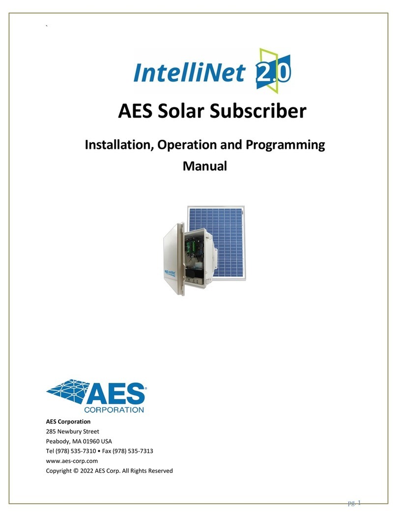
AES Solar Subscriber Kit
Quick Start Guide
AES Corporation www.aes-corp.com
285 Newbury St. Peabody, MA 01960 40-SOLAR Rev 0.3 1/12/2023
Pg.1 of 1
Overview
The AES 3100S-PKG (Solar Subscriber Kit) is designed for applications where a solar powered AES subscriber is
needed.
Included in box
•AES Solar Subscriber 1 ea. AES P/N 3100S
•18 Ah Gel Cell Battery 1 ea. AES P/N 81810
•Subscriber Mounting Bracket 1 ea. AES P/N 30-3100-MB
•Water proofing tape 1 ea. AES P/N 56-7701
•Coax, 10 ft. 1 ea AES P/N 13-0345-10
•Antenna 1 ea. AES P/N 7264-PA
•Antenna mount bracket 1 ea. AES P/N 52-0057
•Quick Start Guide 1 ea. AES P/N 40-3100-QSG
•Solar Panel 1 ea. AES P/N 56-3100-SP
Not Included:
Wiring, for solar panel connection
Pre-Installation
NOTE: Detailed installation instructions can be found in the Installation and Operation Manual AES P/N 40-SOLAR.
Important! Install location needs to account for solar exposure, access to the AES RF mesh network, and placement
to prevent unauthorized subscriber access.
Important! Subscriber physical installation requires a mounting point that can support the weight of the enclosure,
the weight of the backup battery, any other equipment mounted, and wind load.
NOTE: Pole diameter must be 1 ¾ in to 2 ½ in max diameter. for use with U bolt clamps. Four (4) clamps are
recommended. Steel band clamps 3/8 in width may be used. For wall mount use ¼ in diameter size.
Installation
Enclosure Mounting:
1. Use the bracket attached to the subscriber enclosure with appropriate mounting hardware to attach to a pole,
wall, or other mounting surface.
2. Provide clearance beneath the solar subscriber enclosure to allow routing of power and antenna wiring.
Wiring:
CAUTION!: Make sure solar panel is disconnected or use other means to be sure there is no voltage present on
solar panel before wiring next step.
3. Run the electrical cable from the solar panel through the weathertight cable entry at the bottom of the enclosure.
4. Place the (+) lead of the solar panel wiring into the (+) lead of the power connector and fasten tightly. See the
diagram below
6. Place the (-) lead of the solar panel wiring into the (-) lead of the power connector and fasten tightly. See the
diagram below
Important! Do not connect solar panel power connector to the subscriber power connector at this step in the
installation.
4. Install the backup battery in the enclosure. Do not connect the backup battery leads at this step.
5. Connect the coax to the external mount antenna. Seal the coax connector at the antenna using the supplied water
proofing tape and sealant.
6. Add water proofing tape and sealant to the end of the coax at the enclosure.
7. Run the external antenna coax cable through the weathertight cable entry at the bottom of the enclosure.
8. Connect the antenna coax cable to the transceiver in the subscriber enclosure.
9. If required, connect a ground wire to the ground stud
Power Up:
1. Verify the solar panel cable wires are in the correct position on the power connector.
2. Verify the antenna coax is connected to the transceiver connector and to the antenna.
NOTE: Solar conditions need to be suitable to power the subscriber and provide battery charge at the next step.
3. Insert the power connector from the solar panel to the subscriber power connector.
4. Connect the backup battery leads. Connect the (+) lead to the (+) terminal of the battery and the (-) lead to the (-)
lead of the battery.
5. After power is applied the subscriber will boot up and operate.


