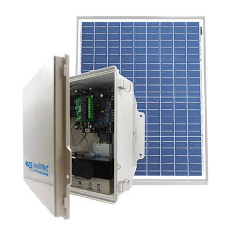
AES 3100S-PKG Owner's manual

`
pg. 1
AES Solar Subscriber
Installation, Operation and Programming
Manual
AES Corporation
285 Newbury Street
Peabody, MA 01960 USA
Tel (978) 535-7310 • Fax (978) 535-7313
www.aes-corp.com
Copyright © 2022 AES Corp. All Rights Reserved

AES SOLAR Subscriber 2
AES P/N 40-3100S Rev. 3, 3/14/2023
This page deliberately left blank

AES SOLAR Subscriber 3
AES P/N 40-3100S Rev. 3, 3/14/2023
Table of Contents
1. Safety Considerations......................................................................................................6
2. Technical Specifications ...................................................................................................6
3. Pre-Installation................................................................................................................8
3.1 Equipment List.................................................................................................................8
3.2 Requirements..................................................................................................................8
Environmental Requirements ...................................................................................8
4. Installation......................................................................................................................8
Mounting the Enclosure............................................................................................8
Weather Proofing Steps ............................................................................................8
5. Wiring.............................................................................................................................9
Earth Ground Connection..........................................................................................9
Battery Connection .................................................................................................10
Battery Replacement...............................................................................................10
Battery Supervision .................................................................................................10
Low Battery Voltage Cutoff .....................................................................................10
Discharge/Recharge ................................................................................................10
6. Programming ................................................................................................................12
6.1 Programming Interface .................................................................................................12
6.2 Logging In ......................................................................................................................12
Change Login Password...........................................................................................12
6.3 Solar Subscriber Interface.............................................................................................13
Page Navigation.......................................................................................................13
Making Configuration Changes ...............................................................................13
Saving Configuration Changes.................................................................................14
6.4 View SOLAR Subscriber Software Version ....................................................................14
6.5 Subscriber Configuration...............................................................................................14
Subscriber ID ...........................................................................................................14
Event Reporting Route ............................................................................................15
6.6 Radio Configuration ......................................................................................................16
6.7 Central Receiver Configuration.....................................................................................16
6.8 Advanced Configuration................................................................................................17
6.9 Zone Input Configuration..............................................................................................18
Zone Input Options for Zones 1 though 4...............................................................18
Alarm Panel Siren Input Options for Zones 5 and 6................................................19
6.10 Consecutive AT Events ..................................................................................................19
6.11 Inverted Fire..................................................................................................................19
6.12 Restoral .........................................................................................................................19
6.13 Status LED Indicators.....................................................................................................20

AES SOLAR Subscriber 4
AES P/N 40-3100S Rev. 3, 3/14/2023
ALM LED Blink Pattern Chart...................................................................................20
6.14 Subscriber Status Check ................................................................................................21
General ....................................................................................................................21
Routing Table...........................................................................................................21
Hardware.................................................................................................................21
6.15 Tools..............................................................................................................................22
Text Message...........................................................................................................22
Alarm History...........................................................................................................22
RF Traffic..................................................................................................................22
IP Traffic...................................................................................................................22
RF Antenna Test ......................................................................................................22
Ping..........................................................................................................................23
System Activity Log..................................................................................................23
6.16 IP Configuration.............................................................................................................23
IP Address –Static ...................................................................................................23
7. System Settings.............................................................................................................23
7.1 Change Password..........................................................................................................23
7.2 Add User........................................................................................................................23
7.3 Buzzer –Onboard Subscriber........................................................................................24
7.4 Uploading/Downloading Settings .................................................................................24
Download Current Settings .....................................................................................24
Upload Preconfigured Settings ...............................................................................24
Reset to Default Configuration................................................................................24
7.5 System Firmware Update..............................................................................................24
Updating..................................................................................................................24
Download Support Files (from subscriber to PC)....................................................24
Restart System.........................................................................................................24
8. Flexible Power Option ...................................................................................................24
9. Reporting......................................................................................................................28
9.1 Compatible Receiver .....................................................................................................28
10. Testing..........................................................................................................................28
11. Maintenance.................................................................................................................28
12. Troubleshooting ............................................................................................................28
13. Repair Information ........................................................................................................29
14. Contact Information ......................................................................................................29
15. Battery Replacement Instructions ..................................................................................29
16. Warranty ......................................................................................................................30

AES SOLAR Subscriber 5
AES P/N 40-3100S Rev. 3, 3/14/2023
List of Tables
Table 1. System Status LED Indicators ..................................................................................20
Table 2. Blink Patterns ..........................................................................................................20
List of Figures
Figure 1. 7007S Solar Enclosure............................................................................................7
Figure 2. Earth Ground Connection Point.............................................................................9
Figure 3. Connecting the Battery Backup ...........................................................................10
Figure 4. Antenna and Surge Suppressor Grounding..........................................................11
Figure 5. Earth Grounding...................................................................................................11

AES SOLAR Subscriber 6
AES P/N 40-3100S Rev. 3, 3/14/2023
1. Safety Considerations
WARNING!
Subscriber antenna or other cables that come in contact with electrical power
lines may result in DEATH or SERIOUS INJURY.
WARNING!
Do NOT install the subscriber unit during a lightning storm.
•Equipment must be installed in accordance with National Electric Code, NFPA 70, local building codes, and
any specific requirements of the Authority Having Jurisdiction (AHJ).
•Ground the antenna, the SOLAR subscriber enclosure, and any surge protector devices to help dissipate surges
away from equipment and personnel. Antenna grounding and surge protectors are for your safety and the
safety of your equipment.
•Periodically test the system for proper operation. AES assumes no responsibility for the equipment’s
failure to operate. AES's sole responsibility is to repair or replace any AES device found to be defective during
the warranty period.
•Avoid dropping or exposing the unit to physical impact that could damage the enclosure or internal
components.
2. Technical Specifications
Requirements
Solar panel (supplied with unit)
•Min. 50W capacity 18V output
•Must select “SOLAR” power option in GUI setup
12 V DC from Rechargeable Backup Battery
in Enclosure
•Minimum 18 Ah size
•Must be SLA (gel cell) battery –due to temperature and
charge controller limitation
Operating Temperature: –13F to 185°F (–20°C to 70°C)
Relative Humidity: Non-condensing
Dimensions: 13.78 in. H × 13.78 W × 5.97 D (Inches)
Weight: 20 pounds with battery
Enclosure Material: Molded fiberglass reinforced polycarbonate, NEMA 4x style
Finish Color: Gray
•Alarm Signal Inputs:
4 Zone Input –four each EOL resistor type –All inputs supervised with trouble and restore
Outputs
•Relay Outputs, 4 ea.
•15 A @ 120 VAC
•10 A @ 250 VAC
Power Supply
Environmental Specifications
Mechanical Specifications
Inputs
Reporting

AES SOLAR Subscriber 7
AES P/N 40-3100S Rev. 3, 3/14/2023
•Low Battery (low battery voltage limit: 11.6 V DC)
•Charger Failure
•Output Power: 2 Watts
•Frequency Range: 450–470 MHz standard (Contact AES for other UHF and VHF frequencies.)
•Four each –field wiring, antenna, solar panel power, and vent. See drawing for locations.
Figure 1. Model 3100S Solar Enclosure
Transceiver
Access

AES SOLAR Subscriber 8
AES P/N 40-3100S Rev. 3, 3/14/2023
3. Pre-Installation
3.1 EQUIPMENT LIST
The following materials are available out of the box:
•AES Solar Subscriber 1 ea. AES P/N 3100S
•18 Ah Gel Cell Battery 1 ea. AES P/N 81810
•Subscriber Mounting Bracket 1 ea. AES P/N 30-3100-MB
•Water proofing tape 1 ea. AES P/N 56-7701
•Coax, 10 ft. 1 ea. AES P/N 13-0345-10
•Antenna 1 ea. AES P/N 7264-PA
•Antenna mount bracket 1 ea. AES P/N 52-0057
•Quick Start Guide 1 ea. AES P/N 40-3100-QSG
•Solar Panel 1 ea. AES P/N 65-3100-SP
3.2 REQUIREMENTS
Environmental Requirements
Select an installation location that meets the Environmental Specifications described in the Technical Specifications
section.
Exposing the subscriber to temperatures below –13°F (–20°C) or above 158°F (70°C) can cause unexpected operation
of the subscriber electronics.
All the enclosure access points into the enclosure must be adequately sealed against water infiltration.
4. Installation
WARNING!
Do NOT install the subscriber unit during a lightning storm or excessive wind conditions.
Mounting the Enclosure
Important!
Solar exposure is critical to operation and sun tilt and location during solar exposure must
be considered.
Mounting location depends on customer application. Customer must consider the suitability
for the application the subscriber will be used for.
Weather Proofing Steps
Important!
Use AES supplied water resistant tape and grease to prevent water entering the enclosure.
Apply this at each of the cable entries into the enclosure.

AES SOLAR Subscriber 9
AES P/N 40-3100S Rev. 3, 3/14/2023
5. Wiring
Earth Ground Connection
Earth ground is provided with a terminal. See the lower left corner in Figure 2 below.
Figure 2. Earth Ground Connection Point

AES SOLAR Subscriber 10
AES P/N 40-3100S Rev. 3, 3/14/2023
Battery Connection
The charge capacity of the subscriber battery is 18 Ah based on enclosure capability.
To connect the backup battery, refer to the following steps:
1. Connect the BLACK wire from (place to the charger terminal) to the negative (‒) side of the battery.
2. Connect the RED wire from (place to the charger terminal) to the positive (+) side of the battery.
Figure 3. Connecting the Battery Backup
Battery Replacement
The type of battery used should be replaced every 3 years or when your application indicates replacement is required.
Replace with the same size and type installed.
Battery Supervision
When solar panel power is present, the battery is tested at approximately 30-second intervals.
When the battery voltage is 11.2 V DC or less for two consecutive test intervals (approximately 60 seconds total), a
low-battery trouble message is transmitted.
When solar panel power is present and a low battery reaches a charge voltage above 12 V DC, a restoral message is
transmitted.
Low Battery Voltage Cutoff
To prevent damage from deep discharge, the SOLAR subscriber disconnects the battery when voltage is less than 10 V
DC.
Discharge/Recharge
The SOLAR panel charges the battery using a charger controller. The battery voltage level conditions are:
•Low Battery (Trouble message): 11.2 V DC or below
•Subscriber Battery Disconnect: Below 10 V DC
•Battery Reconnect (Restoral message): Above 12 V DC

AES SOLAR Subscriber 11
AES P/N 40-3100S Rev. 3, 3/14/2023
A protective surge suppressor (AES Model 7230) option (separately purchased) may be installed in line with any type
of remotely installed antenna, as shown in the diagram below. The surge suppressor and outdoor antenna must be earth
grounded.
Figure 4. Antenna and Surge Suppressor Grounding
Figure 5. Earth Grounding

AES SOLAR Subscriber 12
AES P/N 40-3100S Rev. 3, 3/14/2023
6. Programming
6.1 PROGRAMMING INTERFACE
The Model 3100S is programmed using a graphical interface through a smartphone, a laptop/tablet, or other
browser-capable device through a Wi-Fi dongle.
The subscriber is connected to a LAN through the J10 Ethernet connector. The default network protocol is DHCP. The
IP address obtained is shown in the app only during subscriber power-up. An example display is shown below. The
actual IP address will depend on the network the subscriber connects to.
Note: If DHCP is not available, the IP address is set to 169.254.100.1.
6.2 LOGGING IN
Connecting to the SOLAR configuration page requires a login. Enter the IP address of the subscriber into a web
browser, then enter your username and password at the login screen. Both the default username and password are
admin (lowercase):
The following screen appears after a successful login:
Change Login Password
1. Click the System tab as shown below:
2. Place the cursor in the Current Password text box. Enter the current password.
3. In the New Password text box, type the new password. Type the new password again in the Confirm box
and click Change Password.

AES SOLAR Subscriber 13
AES P/N 40-3100S Rev. 3, 3/14/2023
6.3 SOLAR SUBSCRIBER INTERFACE
Page Navigation
Individual pages are listed in a tab bar. To go to a page, click the associated tab.
For example, the Tools page is accessed by clicking Tools:
Each page displays a set of controls. Use the control to expand the control window. In this example, expanding
Alarm History allows you to view messages similar to the example below:
Use the control to collapse the window.
The Log Out control ends the configuration session and returns to the Login screen.
Making Configuration Changes
Configuration settings are made and changed using either the dropdown or slider switch controls in the window.
The dropdown provides a list to select from:
The slider switch provides one of two values to select:
:

AES SOLAR Subscriber 14
AES P/N 40-3100S Rev. 3, 3/14/2023
Saving Configuration Changes
Saving configuration changes requires the following steps:
1. When you are finished making changes, select and click Save Changes. The Saved new settings!
acknowledgement appears:
2. You may finish and save your changes immediately, or you can make additional changes and then save all
changes at once afterward.
3. If done making changes, click the Update tab shown in the browser (highlighted in red in the figure below):
The Status window displays changes:
6.4 VIEW SOLAR SUBSCRIBER SOFTWARE VERSION
The SOLAR software version is visible in the System tab under the System Firmware Upgrade panel.
Select the System tab, as shown in the following figure:
The version number is displayed in the System Firmware Upgrade section:
6.5 SUBSCRIBER CONFIGURATION
Subscriber ID
Subscriber ID is set in the Configuration tab.
1. From the main menu, select the Configuration tab.

AES SOLAR Subscriber 15
AES P/N 40-3100S Rev. 3, 3/14/2023
Note:
Remote programming of Sub ID and Cipher Code is not possible. Also, the Subscriber ID
number must be unique from all other Sub ID numbers in the system.
2. Change the Sub ID by entering a four-character hex (0‒9 and A‒F) identification number. Valid values are
0001 to FFFF.
Event Reporting Route
1. From the main menu, click the Configuration tab.
2. In the Event Reporting panel, click the Reporting Route dropdown and select the path for the subscriber to
communicate.
Complete the configuration using the links shown below for the Event Reporting path selected for the subscriber:
•Radio Only:
•NOTE: Applicable to solar only.
•Radio and Internet:
•, Central Receiver Configuration and Subscriber IP Address under Advanced Configuration.
•Radio and Internet Backup:
•, Central Receiver Configuration and Subscriber IP Address under Advanced Configuration.
•Internet and Radio Backup:
•, Central Receiver Configuration and Subscriber IP Address under Advanced Configuration.
•Internet Only: Central Receiver Configuration and Subscriber IP Address under Advanced Configuration.

AES SOLAR Subscriber 16
AES P/N 40-3100S Rev. 3, 3/14/2023
6.6 RADIO CONFIGURATION
The Radio Configuration panel contains subscriber settings.
To set Radio Configuration:
1. Click the Configuration tab.
2. Scroll to the Radio Configuration panel.
•Cipher: Enter the four-character hex (0-9 and A-F) cipher code (dealer code) assigned by the system
administrator. Valid values are 0000 to FFFF.
Note:
The code must match the AES 7170 IP-Link cipher code for the network that the
subscriber is to join. The subscriber will not join the mesh network if the cipher code is
incorrect.
•Check-In Time: Enter Check-In interval time in hours and minutes. The default is 23:45 (23 Hr. 45
Min).
Note:
Using short Check-In times generates more traffic on the network.
•Communication Timeout: Communication Timeout is the time the subscriber waits for an ACK as a
reply to a transmitted packet before going into RF Trouble mode. The range is 1‒300 seconds. The
default (recommended) time is 120 seconds.
•Repeating: Set Repeating to Enabled/Disabled by clicking the Repeating switch.
6.7 CENTRAL RECEIVER CONFIGURATION
The Central Receiver panel contains Internet connection settings to the MultiNet/INCC receiver.

AES SOLAR Subscriber 17
AES P/N 40-3100S Rev. 3, 3/14/2023
To set Central Receiver Configuration:
1. Click the Configuration tab.
2. Scroll to the Central Receiver panel.
•IP Group ID: Enter the assigned IP Group ID found in Business Unit Settings.
•Primary Receiver IP: Enter the Primary receiver IP address.
•Primary Receiver Port: Enter the Primary receiver port number.
NOTE –The following is applicable to dual receiver setups only.
•Secondary Receiver IP: Enter the Secondary receiver IP address.
•Secondary Receiver Port: Enter the Secondary receiver port number.
•Internet Check-In: Enter the check-in time interval for the subscriber.
•MCT Delay: Enter the MCT (Multiple Communications Technology) Timeout. The MCT Timeout
sets the amount of time the subscriber tries to send messages though one communication technology
before giving up and switching to the other technology.
6.8 ADVANCED CONFIGURATION
From the Advanced Configurations menu, you can configure Secondary Alarm Delay, TTL (Time to Live) and
subscriber IP address settings. To configure these settings:
1. Select the Configuration tab.
2. Scroll to the Advanced Configuration panel.
•Secondary Alarm Delay
Enter the number of seconds to allow between data transmissions from the subscriber. The range is
1─330 seconds. The default (recommended) time is 10 seconds.
Note:
The first message is sent immediately without delay. Messages that follow are delayed.
•TTL (Time-To-Live) Configuration
Time-to-Live settings are for managing the performance of the AES mesh network. TTL is the length of
time a packet message transmission for a specific setting is retried by a subscriber in the AES mesh
network. The subscriber will stop attempting to transmit the packet when the TTL limit has expired.
To set Time-to-Live:
1. Scroll to the Configuration tab.
2. Select the Advanced Configuration panel and configure the setting:
Message Type
TTL
CHECK-IN
10 minutes
STATUS
10 minutes
ALARM
3:00 hours
TROUBLE
3:00 hours
RESTORAL
3:00 hours
INTELLIPRO
3:00 hours
SPECIAL
10 minutes

AES SOLAR Subscriber 18
AES P/N 40-3100S Rev. 3, 3/14/2023
•Subscriber IP Address Information
To set the subscriber IP address (applicable only if IP access is available and used):
1. Scroll to the Configuration tab.
2. Select the Advanced Configuration panel and configure the setting:
Subscriber IP Address type: Select STATIC or DHCP
If STATIC address is selected, enter the following information:
IP Address –The IP address of the subscriber
Subnet Mask
Gateway
DNS Server 1 (Optional)
DNS Server 2 (Optional)
6.9 ZONE INPUT CONFIGURATION
Zone input for the Model 3100S. The 7094A IntelliPro configuration note applicable. See Accessories tab.
You can verify that a 7094A IntelliPro is installed by selecting the Status tab and checking the Hardware panel.
To configure zone inputs on the SOLAR click the Accessories tab shown below:
The SOLAR subscriber has six zone inputs, zones 1 through 6, as shown below:
Zone Input Options for Zones 1 though 4
The following options are the default choices on the dropdown menu of Zones 1 through 4:
Bypassed –zone input is ignored
Normally Open
Normally Closed
Supervised
When the Fire Zones switch is set to Yes and Inverted Fire is set to Yes, then the Fire and Inverted Fire options will be
listed in the dropdown options as shown below:

AES SOLAR Subscriber 19
AES P/N 40-3100S Rev. 3, 3/14/2023
Zone Programming
Zone Input Condition
Supervised
Bypass
Fire
Inverted Fire
2.2k ohm EOL resistor
circuit
Normal
Input Ignored
Normal
Normal
Open circuit
Alarm
Input Ignored
Trouble
Alarm
Short/closed circuit
Alarm
Input Ignored
Alarm
Trouble
Alarm Panel Siren Input Options for Zones 5 and 6
Inputs for zones 5 and 6 pertain to security alarm panel siren output. The alarm panel condition is detected by the
subscriber through the zone input and a message sent to the central monitoring station. The following types of Siren
Alarm input types can be programmed for zones 5 and 6:
•Bypassed –zone input is ignored
•Temporal/Pulse alarm pattern
•Steady/Even alarm pattern
Connect the Alarm Panel Siren terminals to the SOLAR subscriber siren input terminals.
6.10 CONSECUTIVE AT EVENTS
Set Consecutive AT Events to Yes for verbose reporting of alarm and trouble messages. This means that alarms and
trouble will be sent continuously alarm-trouble-alarm-trouble. Set to No for non-verbose reporting, which means that an
alarm can be sent, then a trouble, but if an alarm happens again without a restoral, the alarm will not be sent.
6.11 INVERTED FIRE
Set Inverted Fire to Yes for an open zone input to report as an alarm and a short on a zone input report as trouble.
Otherwise, the default setting of No which reports open on a zone input as trouble and a short on a zone input as an
alarm (if Fire Zones = Yes).
Note:
Set all unused zones to Bypassed. Do not install EOL resistors on
Bypassed zones.
6.12 RESTORAL
Restoral messages are sent for the zone when the Restoral switch is set to Yes.

AES SOLAR Subscriber 20
AES P/N 40-3100S Rev. 3, 3/14/2023
6.13 STATUS LED INDICATORS
The four LED indicators on the Model 3100S main circuit board show the system status. The LEDs are located in the
lower left corner of the circuit board above the J6 connector:
Table 1. System Status LED Indicators
LED
Color
Function
ALM
Red
Status / troubleshooting indicator, “blink”
WA
Yellow
Steady On = Waiting for acknowledgment of lasttransmission
SteadyBlinking= Noton Network; Off = Normal
TX
Yellow
On = radio transmit
RX
Green
On =Radio transceiverreceivingRFsignal.
NOTE:IfRXis onsteady longerthan20seconds, thenthere is aninterferingRFsignal. Any
RF signals on the same frequencyas the subscriber andstrongenough to break the squelchwill
alsocause the RX light to remainon.
Trbl
Red
Blinking Continuously = Trouble Output Condition
ALM LED Blink Pattern Chart
The chart below shows blink patterns displayed by the ALM LED and what each blink pattern means.
Table 2. Blink Patterns
Blink Type
Pattern
Possible Meaning(s)
Steady blink
•••
Normal operation
Short-short blink
•••
Low battery
Short-long
•••
Zone input in alarm or
trouble/off normal
Short-short-long
•••
Low battery and zone in
alarm/trouble
Short-short-pause-short
•••
AC Fault
Short-short-pause-short-short
•••
AC Fault and low battery
Steady/no blink
Self-test failure (excluding low
battery and AC)
Symbols as follows: "◼"= short blink, " " = long blink
Period betweenpatternsisabout 1 second.The chart shows the pattern repeated3 times.
Other manuals for 3100S-PKG
1
Table of contents
Other AES Inverter manuals