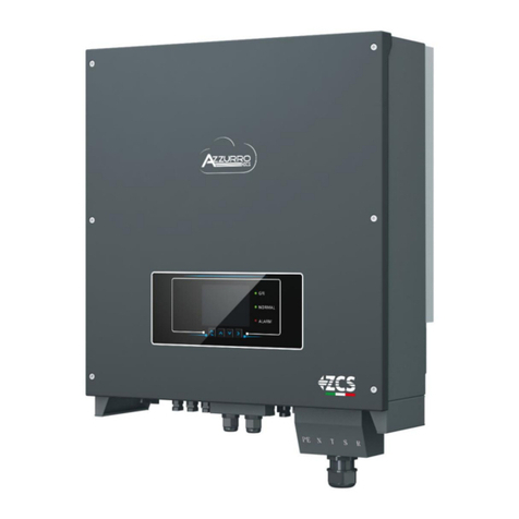
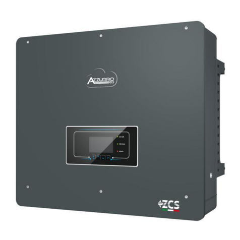
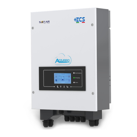
ZCS AZZUPRO 5-20-ZSS User manual

QUICK GUIDE
5-20-ZSS HYBRID INVERTER
Rev. 2.0 –17/04/2023

TABLE OF CONTENTS
TABLE OF CONTENTS
1. INSTALLATION AND DISTANCES
2. WALL INSTALLATION
3. LIGHTS AND BUTTONS
4. MAIN MENU
5. QUICK INFO ON SYSTEM STATUS
6. CONNECTING TO THE GRID
7. PHOTOVOLTAIC CONNECTION
8.1.1 PYLONTECH BATTERY CONNECTION –1 BATTERY TOWER
8.1.2 PYLONTECH BATTERY SETTINGS ON INVERTER -1 BATTERY TOWER
8.2.1 PYLONTECH BATTERY CONNECTION –2 BATTERY TOWERS SC500 & SC1000
8.2.2 PYLONTECH BATTERY SETTINGS ON INVERTER -2 BATTERY TOWERS SC500 & SC1000
8.3.1 PYLONTECH BATTERY CONNECTION –2 BATTERY TOWERS SC500 & SC1000 Wi-Fi/USB
8.3.2 PYLONTECH BATTERY SETTINGS ON INVERTER -2 BATTERY TOWERS SC500 & SC1000 Wi-Fi/USB
9.1.1 WECO 5K3 BATTERY CONNECTION –1 BATTERY TOWER
9.1.2 5K3 WECO BATTERY SETTINGS ON INVERTER -1 BATTERY TOWER
9.2.1 5K3 WECO BATTERY CONNECTION –2 BATTERY TOWERS
9.2.2 5K3 WECO BATTERY SETTINGS ON INVERTER -2 BATTERY TOWERS
9.3.1 5K3 XP WECO BATTERY CONNECTION –1 BATTERY TOWER
9.3.2 5K3 XP WECO BATTERY SETTINGS ON INVERTER -1 BATTERY TOWER
9.3.3 5K3XP WECO BATTERY START-UP
9.4.1 5K3 XP WECO BATTERY CONNECTION –2 BATTERY TOWERS
9.4.2 5K3 XP WECO BATTERY SETTINGS ON INVERTER -2 BATTERY TOWERS
9.5 MIXED CONNECTION BETWEEN 5K3 WECO AND 5K3 XP WECO BATTERIES
10.1.1 AZZURRO HV BATTERY CONNECTION –1 BATTERY TOWER
10.1.2 AZZURRO HV BATTERY SETTINGS ON INVERTER -1 BATTERY TOWER
10.2.1 AZZURRO HV BATTERY CONNECTION –2 BATTERY TOWERS
10.2.2 AZZURRO HV BATTERY SETTINGS ON INVERTER -2 BATTERY TOWERS
11.1 DIRECT READING VIA CURRENT SENSORS
11.2 METER READING
11.3 METER SETTING
11.4 CHECKING THE CORRECT READING OF THE METER
12. INITIAL START-UP
13. FIRST CONFIGURATION
14. CHECKING THE INVERTER SETTINGS
15. CHECKING THE BATTERY SETTINGS
16. QUICK INFO ON SYSTEM STATUS
17. OPERATING STATUSES IN AUTOMATIC MODE
18.1 EPS MODE (OFF GRID)
18.2 EPS MODE (OFF GRID) -WIRING PROCEDURE AND INSTALLATION TYPES
18.3 EPS MODE (OFF GRID) -OPERATION
18.4 EPS MODE (OFF GRID) -MENU ENABLING
18.5 EPS OPERATING MODE (OFF GRID)
19.1 PARALLEL INVERTER MODE -CONFIGURATION
19.2 PARALLEL INVERTER MODE -SETTINGS
20. OPERATION OF PHOTOVOLTAIC SYSTEM ONLY
1. INSTALLATION
2. WALL INSTALLATION
1. INSTALLATION AND DISTANCES
20 20
Distances for installation of a single inverter
Distances for installation of multiple inverters
Always wear protective
clothing and/or personal
protective equipment
Always consult the
manual
General notice -
Important Safety
Instructions
30
3030
Maximum height from ground permitted: 180 cm
Step 1: Position the mounting bracket on the
wall, mark the fixing points.
Step 2: Insert the expansion bolts vertically into
the hole, make sure that the insertion depth is
neither too shallow nor too deep.
Step 3: Fix the mounting bracket to the wall
using the expansion bolts with nuts.
Step 4: Position the 3PH HYD5000-HYD20000-
ZSS inverter on the mounting bracket.
Step 5: Use the grounding hole to electrically
ground the inverter
Step 1 Step 2 Step 3
Step 4 Step 5

1
5
6
7
2 3 4
9
8
10
11
12
13
1. Menu/Back
2. Up
3. Down
4. Enter/Forward
5. On-grid Status
6. Off-grid Status
7. Alarm status
8. System status
9. PV production
10. Grid power
11. Home consumption
12. Battery power
13. Date and time
14. Wi-Fi signal
15. PV system status
14
3. LIGHTS AND BUTTONS
Main menu
1. Basic settings
2. Advanced settings
3. Event list
4. System Info
5. Software Update
6. Energy statistics
From the main menu, press
“Menu/Back” to enter the main
menu.
4. MAIN MENU
Status of the HYD-ES
inverter
On-Grid
Green light
Off-Grid
Green light
Alarm
Red light
On-Grid On
Standby (On-Grid) Intermittent
Off-Grid On
Standby (Off-Grid) Intermittent
Alarm On
15
1. Language
2. Date and Time
3. Safety parameters
4. Working mode
5. Self-test
6. Config.input Channels
7. EPS Mode
8. Commun. Address.
Select.
1. Battery parameters
2. Battery active
3. Zero grid feed-in mode
4. IV Curve Scan
5. Logic interface
6. Factory reset
7. Parallel settings
8. Bluetooth Reset
9. CT Calibration
PWD: 0715
1. List of current events
2. List of historical events
1. Inverter Info
2. Battery Info
3. Safety parameters
Start Update ...
PWD: 0715
Today Week Month Year Life Cycle
PV prod.PV prod.PV prod.PV prod.PV prod.
AutoCon AutoCon AutoCon AutoCon AutoCon
Export Export Export Export Export
Consumption Consumption Consumption Consumption Consumption
AutoCon AutoCon AutoCon AutoCon AutoCon
Import Import Import Import Import

5. QUICK INFO ON SYSTEM STATUS
6. CONNECTING TO THE GRID
1Battery input terminals 7DRMs
2DC Switch 8COM
3PV input terminals 9Port 1 for parallel connection
4Privileged load connection port 10 Port 0 for parallel connection
5Grid connection port 11 CT (current sensors)
6USB/Wi-Fi 12 LCD
Step 1:Select the
appropriate cable
type and
specifications. Then
pass the cables
through the
terminal.
Step 2: Lock the
cables into the
holes on the
terminal and
tighten them with
the Allen key.
Step 3: Connect the
terminal to the machine
port and turn the clamp in
a clockwise direction
Component Description Recommended
cable type
Recommended cable
specification
LOAD
L1/L2/L3
Multi-core copper
cable for outdoor
use
Cross-section area of the
conductor: 6~10 mm2
N
PE
AC
L1/L2/L3
Multi-core copper
cable for outdoor
use
Cross-section area of the
conductor: 10~16 mm2
N
PE

7. PHOTOVOLTAIC CONNECTION
Cross-sectional area (mm2)
Outer cable area (mm2)
Range Recommended
value
4.0~6.0 4.0 4.5~7.8
Recommended specifications for
DC input cables
Procedure:
1) Prepare the positive and negative photovoltaic cables.
Insert the crimped positive and negative cables into the corresponding photovoltaic connectors.
1. Positive contact
2. Negative contact
3. Positive connector
4. Negative connector
Make sure that all the DC string parameters are acceptable to the inverter according to the technical specifications
given in the datasheet and in the Azzurro ZCS configurator. In addition, check that the polarities of the photovoltaic
cables are correct. Insert the positive and negative connectors into the inverter until you hear a “click” sound.
Before removing the positive and negative PV connectors, make
sure that the DC rotary circuit breaker is in the OFF position.
Use a MC4 wrench to disconnect the
photovoltaic connectors
NOTE: All MPPT inputs of the inverter should be populated, even if the system only has one
string. Use “Y” cables or a DC square to split the string.
Configure the inverter in parallel mode:
Basic settings
Channel configuration (Channel 3: PV input 1, Channel 4: PV input 1)
ATTENTION Before connecting/disconnecting the PV panels to the inverter,
check that the DC circuit breaker on the inverter is in the OFF position.

8.1.1 PYLONTECH BATTERY CONNECTION –1 BATTERY TOWER
Battery
Power connections between batteries
and BMS:
Batteries are connected IN SERIES to
each other:
•Negative input (-) of battery 1
connected to positive input (+) of
battery 2.
•Negative input (-) of battery 2
connected to positive input (+) of
battery 3.
•…..
•Negative input (-) of battery N-1
(second-last) connected to positive
input (+) of battery N (last).
Connect each battery to the metal rack
and connect accordingly to the ground
system.
Communication connections between batteries
and BMS:
•Link port of the BMS to link port 0 of battery 1.
•Link port 1 of battery 1 must be connected to link
port 0 of battery 2.
•…
•Link port 1 of battery N-1 (second-last) must be
connected to link port 0 of battery N (last).
Power and communication connections between batteries and BMS
BMS
The BMS is connected in parallel to the
series consisting of the batteries:
•Negative input (-) of the BMS
connected to the negative input (-) of
battery N (last) in the series.
•Positive input (+) of the BMS
connected to positive input (+) of
battery 1.
PE cable
Power and communication connections between BMS and inverter
ADD: 000000
Communication connections between BMS and
inverter:

SC500 & SC1000 BMS communication:
•ADD communication address: 000000
•Cable connected to BMS on CAN/Link port B
SC500 & SC1000
BMS
Wi-Fi/USB SC500 & Wi-Fi/USB SC1000 BMS communication:
•ADD communication address: 000000
•Cable connected to BMS on CAN port
Wi-Fi/USB SC500 &
Wi-Fi/USB SC1000
BMS
Connect the cable connected to position 4 (blue wire) pin 7 of the inverter COM connector.
Connect the cable connected to position 5 (white-blue wire) pin 8 of the inverter COM connector.
Connect the cable connected to position 2 (orange wire) pin 9 of the inverter COM connector.
The end labelled inverter must be cut leaving only the wires connected to pins 2 (orange wire), 4
(blue wire) and 5 (white-blue wire).
Screw-in COM port
Snap-in COM port

Power cable ends with
connectors to connect to the
BAT1 channel of the inverter.
Cable ends with fast
connectors to
connect to the BMS
Power cables
supplied
13
4 5
2
COM port PIN
(inverter) Battery communication Notes
7CAN H (blue wire) Communication with the BMS
of the lithium battery, the CAN
of the inverter adapts to the
BMS of the lithium battery.
8CAN L (white-blue
wire)
9GND.S (orange wire)
Power connections between BMS and inverter:

8.1.2 PYLONTECH BATTERY SETTINGS ON INVERTER -1 BATTERY TOWER
Set the battery channels in the inverter according to the configuration of the battery
towers.
Configure the inverter channels:
Basic settings
Channel configuration:
When connecting 1Pylontech tower:
oInput channel 1 – BAT input 1;
oInput channel 2 – Not used.
To set the battery parameters:
Advanced settings
0715
Battery parameters:
When connecting 1Pylontech tower:
-Battery 1:
oType:Pylon ;Address:00;Maximum charge/discharge current:25 A;
Depth of discharge:80%.
BATTERY 1
1.Battery
type Pylon
2.Battery
address 00
3.Maximum
charge (A)
25.00
A
4.Maximum
discharge (A)
25.00
A
5.Depth of
Discharge 80%
6.Save
8.2.1 PYLONTECH BATTERY CONNECTION –2 SC500 & SC1000 BATTERY TOWERS
BMS 1
•Communication address:000000
•Connect the communication cable between
the two BMSs to link port A.
BMS 2
•Communication address:100001
•Connect the communication cable between the
two BMSs to link port B.
Inverter
BMS 1 BMS 2
Communication connections between the two SC500 & SC1000
Battery Management Systems

BAT1 INPUT BAT2 INPUT
+ - + -
Each BMS will be connected via power cables
(+ and -) to the two inputs of the inverter, in
particular make sure to connect:
BMS 1 → Channel BAT1 of the inverter
BMS 2 → Channel BAT2 of the inverter
INVERTER
Power connections between SC500 & SC1000 BMS and inverter
BMS 1 BMS 2
BATTERY TOWER 1 BATTERY TOWER 2
Note: Refer to the previous chapter for the communication and power
connections of each tower.

8.2.2 PYLONTECH BATTERY SETTINGS ON INVERTER -2 SC500 & SC1000 BATTERY TOWERS
Set the battery channels in the inverter according to the configuration of the battery towers.
Configure the inverter channels:
Basic settings
Channel configuration:
When connecting 2Pylontech towers:
oInput channel 1 – BAT input 1;
oInput channel 2 – BAT input 2.
To set the battery parameters:
Advanced settings
0715
Battery parameters:
When connecting 2Pylontech towers:
-Battery 1:
oType:Pylon ;Address:00;Maximum charge/discharge current:25 A; Depth of
discharge:80%.
-Battery 2:
oType:Pylon ;Address:01;Maximum charge/discharge current:25 A; Depth of
discharge:80%.
BATTERY 1
1.Battery type Pylon
2.Battery address 00
3.Maximum charge (A) 25.00A
4.Maximum discharge (A) 25.00A
5.Depth of Discharge 80%
6.Save
BATTERY 2
1.Battery type Pylon
2.Battery address 01
3.Maximum charge (A) 25.00A
4.Maximum discharge (A) 25.00A
5.Depth of Discharge 80%
6.Save

8.3.1 PYLONTECH BATTERY CONNECTION –2 Wi-Fi/USB SC500 & SC1000 BATTERY TOWERS
BMS 1
•Communication address:100001
•Connect the communication cable between the
two BMSs to link port A.
•Link port Bof BMS 1 COM port of the inverter
BMS 2
•Communication address:010001
•Connect the communication cable between the
two BMSs to link port B.
BMS 1
BMS 2
Communication connections between the two Wi-Fi/USB SC500 & SC1000 BMSs
BATTERY TOWER 1 BATTERY TOWER 2
Note: Refer to the previous chapter for the communication and power
connections of each tower.

8.3.2 PYLONTECH BATTERY SETTINGS ON INVERTER -2 Wi-Fi/USB SC500 & SC1000 BATTERY TOWERS
Set the battery channels in the inverter according to the configuration of the battery towers.
Configure the inverter channels:
Basic settings
Channel configuration:
When connecting 2Pylontech towers:
oInput channel 1 – BAT input 1;
oInput channel 2 – BAT input 1.
To set the battery parameters:
Advanced settings
0715
Battery parameters:
When connecting 2Pylontech towers:
-Battery 1:
oType:Pylon ;Address:01;Maximum charge/discharge current:50 A; Depth of
discharge:80%.
BATTERY 1
1.Battery type Pylon
2.Battery address 01
3.Maximum charge (A) 50.00A
4.Maximum discharge (A) 50.00A
5.Depth of Discharge 80%
6.Save
NOTE:The first time the inverter is switched on, error code ID044 (PvConfigError) may appear in
the current event list for about 5/10 minutes.Do not switch off or restart the inverter as this
behaviour is caused by the BMS configuration.After this waiting period, the system will start
operating normally.

9.1.1 WECO 5K3 BATTERY CONNECTION –1 BATTERY TOWER
Batteries are connected IN SERIES to each other:
•Negative input (-) of battery 1 connected to positive input (+)
of battery 2.
•Negative input (-) of battery 2 connected to positive input (+)
of battery 3.
•…..
•Negative input (-) of battery N-1 (second-last) connected to
positive input (+) of battery N (last).
The HV-BOX is connected in parallel to the series consisting of
the batteries:
•Negative input (-) of the HV-BOX connected to negative input
(-) of battery N (last) in the series.
•Positive input (+) of the HV-BOX connected to positive input
(+) of battery 1.
Connect each device to the ground system.
Communication connections between batteries and
HV-BOX:
•CAN1-B of the HV-BOX to CAN-A of battery 1.
•LINK of HV-BOX to LINK-A of battery 1.
•CAN- B of battery 1 to CAN-A of battery 2.
•LINK-B of battery 1 to LINK-A of battery 2.
•…
•CAN-B of battery N-1 (second-last ) to CAN-A of
battery N (last).
•LINK-B of battery N-1 (second-last) to LINK-A of
battery 2 (last).
Battery
module
HV BOX
The Dip switches of the battery modules must be set:
PE cable
Power and communication connections between batteries and HV-BOX
Switch from battery 1
to battery N-1
(second-last)
Switch to battery N
(last)

BAT1 INPUT BAT2 INPUT
+ - + -
Power cables
supplied
HV-BOX
Power and communication connections between HV-BOX and inverter
Power connections between HV-BOX and inverter:
The HV-BOX will be connected via power cables (+ and -) to
the two inputs of the inverter, in particular make sure to
connect:
Inverter channel 01 HV-BOX Channel BAT1 of the
inverter
Inverter channel 02 HV-BOX Channel BAT2 of the
inverter
HV-BOX communication:
•ADD communication address: 00000010
•Communication cable connections between HV-BOX
and inverter:
CAN2-A HV-BOX COM port inverter
Communication connections between HV-BOX and inverter:
-Connect cable CAN H (White-Orange wire) pin 7 of the inverter COMM connector.
-Connect cable CAN L (Orange wire) pin 8 of inverter COM connector.
Screw-in COM port
Snap-in COM port

Set the battery channels in the inverter according to the configuration of the battery towers.
Configure the inverter channels:
Basic settings
Channel configuration:
When connecting 1 5k3 WeCo tower:
oInput channel 1 – BAT input 1;
oInput channel 2 – BAT input 1.
To set the battery parameters:
Advanced settings
0715
Battery parameters:
When connecting 1 5k3 WeCo tower:
-Battery 1:
oType:WeCo ;Address:00;Maximum charge/discharge current:25 A(for inverter HYD
3PH 5000-8000 ZSS) or 50 A(for inverter HYD 3PH 10000-20000 ZSS) ;Depth of
discharge:80%.
9.1.2 5K3 WECO BATTERY SETTINGS ON INVERTER -1 BATTERY TOWER
HYD 5000 ZSS/HYD 8000 ZSS HYD 10000 ZSS/HYD 20000 ZSS
BATTERY 1 BATTERY 1
1.Battery type WeCo 1.Battery type WeCo
2.Battery address 00 2.Battery address 00
3.Maximum charge (A) 25.00A 3.Maximum charge (A) 50.00A
4.Maximum discharge (A) 25.00A 4.Maximum discharge (A) 50.00A
5.Depth of Discharge 80% 5.Depth of Discharge 80%

9.2.1 5K3 WECO BATTERY CONNECTION –2 BATTERY TOWERS
HV-BOX 1
•Communication address:00000010
•Connect the communication cable between
the two HV-BOXES to CAN2-B port.
Communication connections between the two HV-BOXES
HV-BOX 2
•Communication address:10000000
•Connect the communication cable between
the two HV-BOXES to CAN2-B port.
Power connections between the two HV-BOXES and inverter
BAT1 INPUT BAT2 INPUT
+ - + -
INVERTER
HV-BOX 1 HV-BOX 2

HV-BOX 1HV-BOX 2
Battery 1
Battery 1
Battery N Battery N
INVERTER
9.2.2 5K3 WECO BATTERY SETTINGS ON INVERTER -2 BATTERY TOWERS
Note: Refer to the previous chapter for the communication and power
connections of each tower.
Set the battery channels in the inverter according to the configuration of the battery towers.
Configure the inverter channels:
Basic settings
Channel configuration:
When connecting 2 5k3 WeCo towers:
oInput channel 1 – BAT input 1;
oInput channel 2 – BAT input 2.
To set the battery parameters:
Advanced settings
0715
Battery parameters:
When connecting 2 5k3 WeCo towers:
-Battery 1:
oType:WeCo ;Address:00;Maximum charge/discharge current:25 A; Depth of
discharge:80%.
-Battery 2:
oType:WeCo ;Address:01;Maximum charge/discharge current:25 A; Depth of
discharge:80%.
BATTERY 1
1.Battery type WeCo
2.Battery address 00
3.Maximum charge (A) 25.00A
4.Maximum discharge (A) 25.00A
5.Depth of Discharge 80%
6.Save
BATTERY 2
1.Battery type WeCo
2.Battery address 01
3.Maximum charge (A) 25.00A
4.Maximum discharge (A) 25.00A
5.Depth of Discharge 80%
6.Save

9.3.1 5K3 XP WECO BATTERY CONNECTION –1 BATTERY TOWER
Batteries are connected IN SERIES to each other:
•Negative input (-) of battery 1 connected to positive input (+)
of battery 2.
•Negative input (-) of battery 2 connected to positive input (+)
of battery 3.
•…..
•Negative input (-) of battery N-1 (second-last) connected to
positive input (+) of battery N (last).
The HV-BOX is connected in parallel to the series consisting of
the batteries:
•Negative input (-) of the HV-BOX connected to negative input
(-) of battery N (last) in the series.
•Positive input (+) of the HV-BOX connected to positive input
(+) of battery 1.
Connect each device to the ground system.
Communication connections between batteries and
HV-BOX:
•CAN1-B of the HV-BOX to CAN-A of battery 1.
•CAN- B of battery 1 to CAN-A of battery 2.
•…
•CAN-B of battery N-1 (second-last ) to CAN-A of
battery N (last).
Battery
module
HV BOX
The Dip switches of the battery modules must be set:
PE cable
Power and communication connections between batteries and HV-BOX
Switch from battery 1
to battery N-1
(second-last)
Switch to battery N
(last)
Battery 1
Battery N
Table of contents
Other ZCS Inverter manuals

ZCS
ZCS Azzurro 3PH 20000TL-V2 User manual

ZCS
ZCS TL Series User manual

ZCS
ZCS Azzurro HYD3000-ZP1 User manual

ZCS
ZCS 3PH 100KTL-HV User manual

ZCS
ZCS HYD 3000-ES User manual

ZCS
ZCS HYDxxxxES Series User manual

ZCS
ZCS AZZURRO Series User manual

ZCS
ZCS 1100TL-G3 User manual

ZCS
ZCS ZCS 1.1K-3KTL User manual

ZCS
ZCS Azzurro HYD 3000 ES User manual