9
10. LCD Setting and Display
Setting Program:
Program Description Selectable option
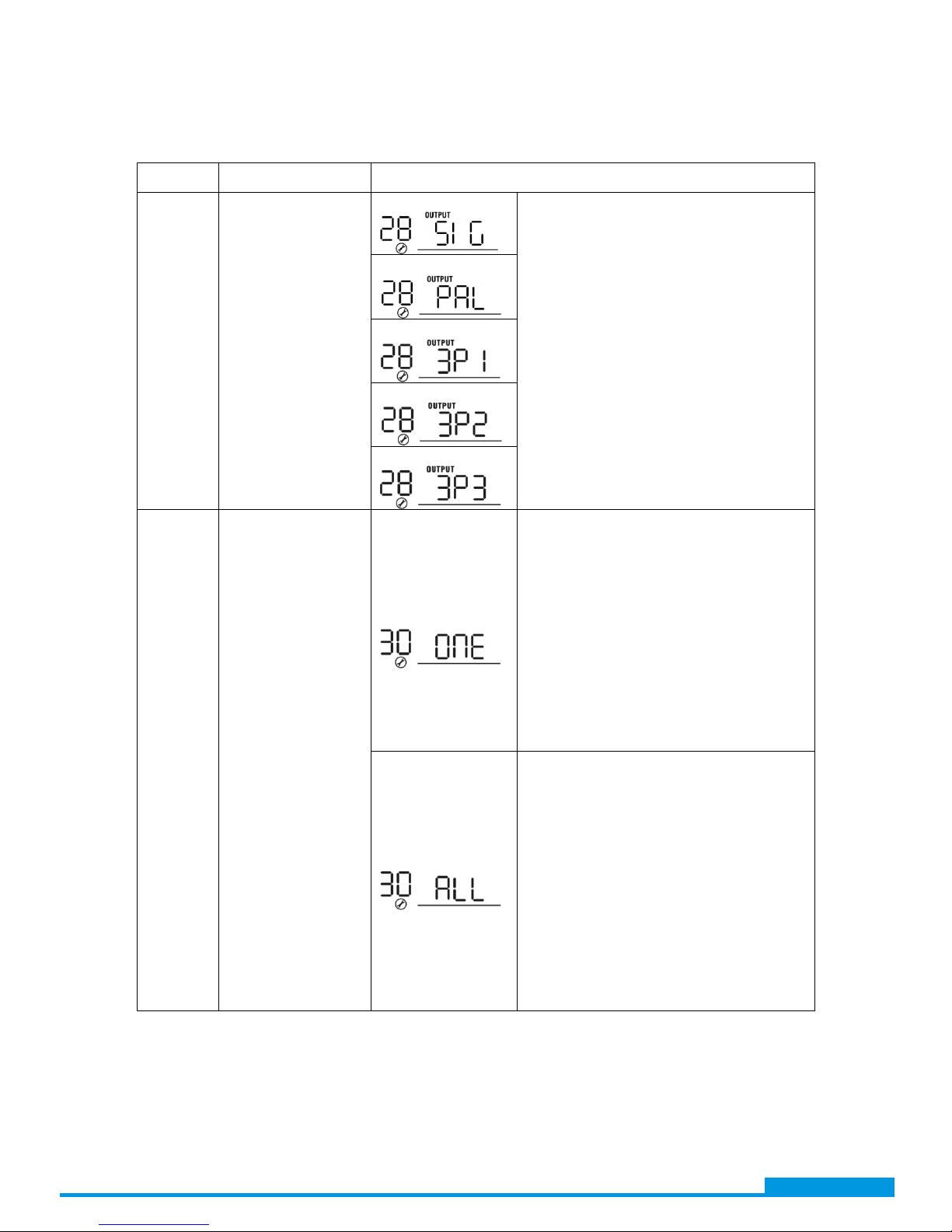
28
AC output mode
*This setting is only
available when the
inverter is in standby
mode (Switch off).
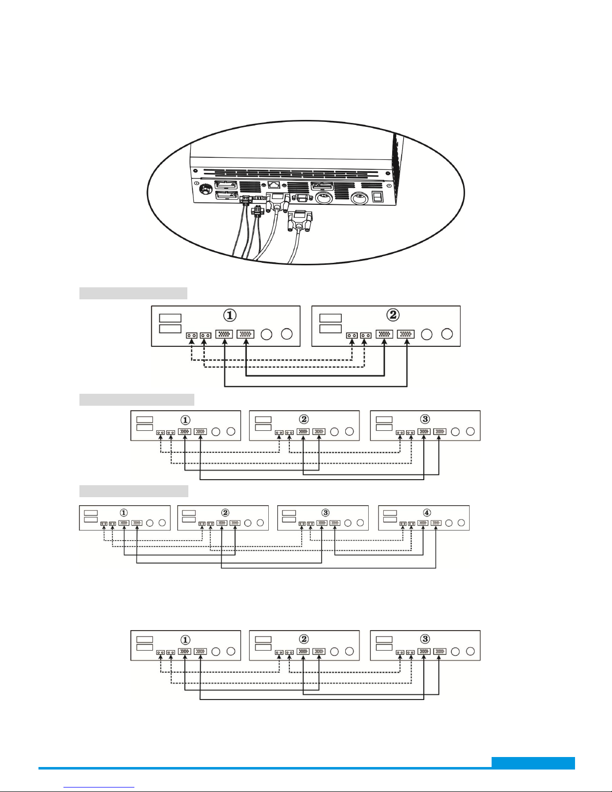
Single:
When the units are used in parallel with
single phase, please select “PAL”in
program 28.
Operation to support three-phase
equipment is required to have three
inverters. This setting for each unit
should be different in L1 phase, L2 phase
and L3 phase separately. Please set up
this setting corresponding to each phase
connection.
Besides, power saving function will be
automatically disabled.
Parallel:
L1 phase:
L2 phase:
L3 phase:
30
PV judge condition
(Only apply for
setting “Solar first”
in program 1:
Output source
priority)
One Inverter
(Default):
When “ONE”is selected, as long as one of
inverters has been connected to PV
modules and PV input is normal, parallel
or 3-phase system will continue working
according to rule of “solar first”setting.
For example, two units are connected in
parallel and set “SOL” in output source
priority. If one of two units has connected
to PV modules and PV input is normal, the
parallel system will provide power to
loads from solar or battery power. If both
of them are not sufficient, the system will
provide power to loads from utility.
All of Inverters:
When “ALL”is selected, parallel or
3-phase system will continue working
according to rule of “solar first”setting
only when all of inverters are connected
to PV modules.
For example, two units are connected in
parallel and set “SOL” in output source
priority. When selecting “ALL”in program
30, it’s necessary to have all inverters
connected to PV modules and PV input is
normal to allow the system to provide
power to loads from solar and battery
power. Otherwise, the system will provide
power to loads from utility.
www.voltacon.com