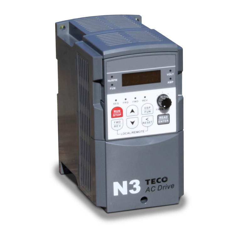
N3 Drive Operations Manual
Table of Contents
Table of Contents
1.0 Introduction.....................................................................................................................................1
2.0 Product Inspection.........................................................................................................................2
2.1 Nameplate Layout ......................................................................................................................2
3.0 Operating Precautions...................................................................................................................3
3.1 Before Power up.........................................................................................................................3
3.2 During Power up.........................................................................................................................4
3.3 Before Operation ........................................................................................................................4
3.4 During Operation ........................................................................................................................5
4.0 Environment and Installation ........................................................................................................6
4.1 Inverter Mounting........................................................................................................................6
Fig.4.1.1 Panel and Enclosure Placement .....................................................................................6
Fig 4.1.2 Din Rail Mounting Clearances.........................................................................................7
5.0 General Wiring Diagram (1 - 2 HP)................................................................................................8
6.0 General Wiring Diagram (3 - 75 HP)..............................................................................................9
7.0 Power Terminals Designations and Ratings (Terminal Block TM1)........................................10
7.1 Power Terminal Configuration TM1..........................................................................................10
7.2 Power Terminal Block TM1 Electrical Ratings and Tightening Torques..................................11
8.0 Inverter Wiring ..............................................................................................................................11
8.1 Input / Output Power Wiring Connections (Terminal TM1) ......................................................11
8.2 Input / Output Power Wiring Noise Suppression......................................................................11
Fig. 8.2 Input / Output Power Wiring Noise Suppression.............................................................11
8.3 Motor Cable Length..................................................................................................................12
8.4 Cable Length vs Carrier Frequency .........................................................................................12
8.5 Inverter Grounding....................................................................................................................12
8.6 Input Power Wiring and Installation Recommendations with Examples ..................................13
Fig. 8.6 Input Power Wiring and Installation Examples................................................................13
9.0 Input / Output Power Section Block Diagram............................................................................14
Fig. 9.0 Power Input / Output Block Diagrams.............................................................................14
10.0 Control Terminals (Terminal Block TM2) .................................................................................15
10.1 Control Terminal Designations (Terminal Block TM2) ..........................................................15
10.2 Control Terminal Layout and Control Switches.....................................................................16
Fig. 10.2.1 Control Terminal TM2 Layout................................................................................16
Fig. 10.2.2 Control Terminal TM2 Layout (Prior to Version 1.3) .............................................16
10.3 Control Terminal Wiring and Connections (Terminal TM2)..................................................16
11.0 Peripheral Power Devices..........................................................................................................17
12.0 Input Fuse Types and Ratings ...........................................................................................18 - 19
13.0 Applicable specifications for circuit breakers and magnetic contactors.............................19
14.0 Reactor Input / Output Specifications ......................................................................................20
15.0 Braking Unit and Braking Resistor Selections........................................................................21
16.0 EMC Filters..................................................................................................................................22
17.0 Keypad Key Functions and Navigation....................................................................................23
17.1 N3 Keypad.............................................................................................................................23
17.2 Keypad LED Functions..........................................................................................................23
17.3 Key Functions........................................................................................................................24
17.4 Keypad Navigation ................................................................................................................25
17.4.1 Basic Keypad Control .................................................................................................25
17.4.2 Local / Remote Function..............................................................................................25
17.4.3 Setting Parameters b(Basic) and A(Advanced)........................................................26
18.0 Control Mode Selection .............................................................................................................27
Cont.
