Lennox e-Lite LV-M080 Series User manual

LV-MO80-180-IOM-
20.04-E
e-Lite
DC INVERTER FREE | LV-MO80 > 180
Installation and Operation Manual


1
1. PRECAUTIONS
CAUTION
PRECAUTIONS...............................................................................1
ATTACHED FITTINGS......................................................................2
OUTDOOR UNIT INSTALLATION.......................................................3
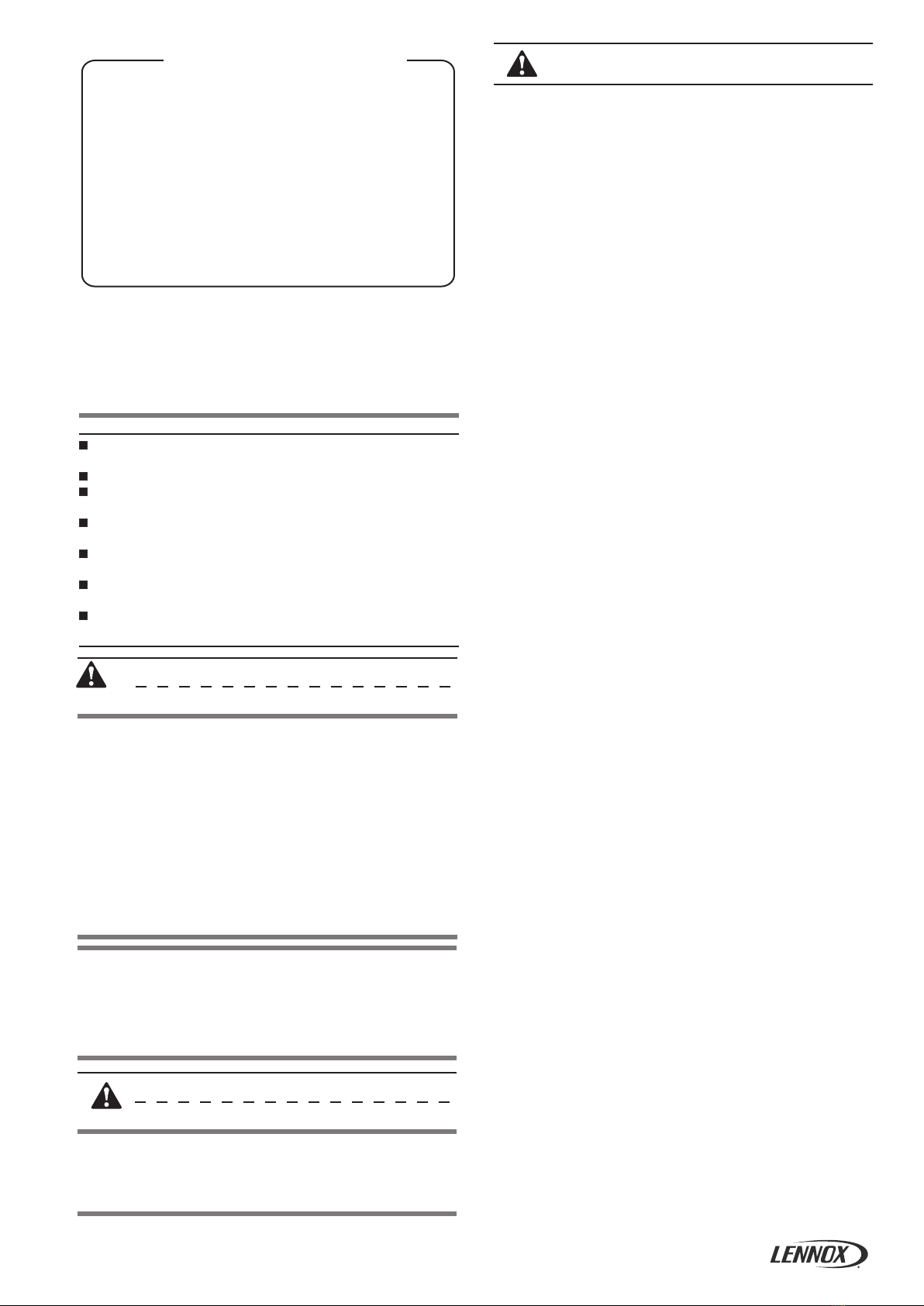
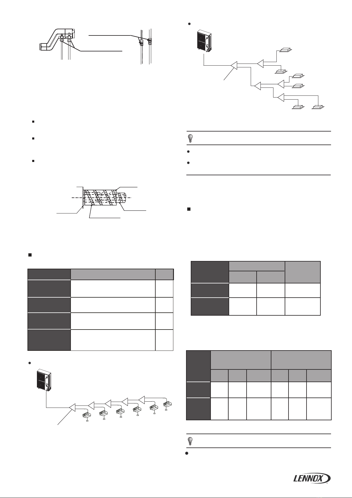
INSTALL THE CONNECTING PIPE.....................................................4
ELECTRICAL WIRING......................................................................9
TEST RUNNING.
..
......
..
..................
..
..........
.................................
.12
PRECAUTIONS ON REFRIGERANT LEAKAGE....................................12
TURN OVER TO CUSTOMER..........................................................12
Ensure that all Local, National and International regulations
are satisfied.
Read this ”PRECAUTIONS ” carefully before Installation.
The precautions described below include the important
items regarding safety. Observe them without fail.
After the installation work, perform a trial operation to check
for any problem.
Follow the Owner’s Manual to explain how to use and
maintain the unit to the customer.
Turn off the main power supply switch (or breaker) before
maintenance the unit .
Ask the customer that the Installation Manual and the Owner’s
Manual should be kept together .
New Refrigerant Air Conditioner Installation
WARNING
THIS AIR CONDITIONER ADOPTS THE NEW HFC
REFRIGERANT(R410A)WHICH DOES NOT DESTROY OZONE
LAYER.
The characteristics of R410A refrigerant are; Hydrophilic, oxid-
izing membrane or oil, and its pressure is approx.1.6 times high-
er than that of refrigerant R22.Accompanied with the new refrig-
erant, refrigerating oil has also been changed ,Therefore, during
installation work, be sure that water, dust, former refrigerant, or
refrigerating oil does not enter the refrigerating cycle.
To prevent charging an incorrect refrigerant and refrigerating oil,
the sizes of connecting sections of charging port of the main
unit and installation tools are charged from those for the
conventional refrigerant.
Accordingly the exclusive tools are required for the new
refrigerant (R410A):
For connecting pipes, use new and clean piping designed for
R410A,and please care so that water or dust does not enter.
Moreover, do not use the existing piping because there are
problems with pressure-resistance force and impurity in it.
CAUTION
Do not connect the Appliance from Main Power Supply.
This unit must be connected to the main power supply by
means of a switch with a contact separation of at least 3 mm.
The installation fuse must be used for the power supply line of
this conditioner.
If the supply cord is damaged, it must be replaced by the
manufacturer or its service agent or a similarly qualified person
in order to avoid a hazard.
An all-pole disconnection switch having a contact separation of
at least 3mm in all poles should be connected in fixed wiring.
The appliance shall be installed in accordance with national
wiring regulations.
The temperature of refrigerant circuit will be high, please keep
the interconnection cable away from the copper tube.
An all-pole disconnection device which has at least 3mm
separation distance in all pole and a residual current
device(RCD)with the rating of above 10mA shall be incorporated
in the fixed wiring according to the national rule.
The power cord type designation is H05RN-R/H07RN-F or above.
Ask an authorized dealer or qualified installation professional to
install/maintain the air conditioner.
Inappropriate installation may result in water leakage,electric shock
or fire.
Turn off the main power supply switch or breaker before
attempting any electrical work.
Make sure all power switches are off.Failure to do so may cause
electric shock.
Connect the connecting cable correctly.
If the connecting cable is connected in a wrong way, electric parts
may be damaged.
When moving the air conditioner for the installation into another
place, be very careful not to enter any gaseous matter other
than the specified refrigerant into the refrigeration cycle.
If air or any other has is mixed in refrigerant, the gas pressure in the
refrigeration cycle becomes abnormally high and it may resultingly
causes pipe burst and injuries on persons.
Do not modify this unit by removing any of the safety guards or
by by-passing any of the safety interlock switches.
Exposure of unit to water or other moisture before installation
may cause a short-circuit of electrical parts.
Do not store it in a wet basement or expose to rain or water.
After unpacking the unit, examine it carefully if there are
possible damage.
Do not install in a place that might increase the vibration of the
unit.
To avoid personal injury (with sharp edges), be careful when
handling parts.
Perform installation work properly according to the Installation
Manual.
Inappropriate installation may result in water leakage, electric shock
or fire.
When the air conditioner is installed in a small room, provide
appropriate measures to ensure that the concentration of
refrigerant leakage occur in the room does not exceed the
critical level.
Install the air conditioner securely in a location where the base
can sustain the weight adequately.
Perform the specified installation work to guard against an
earthquake.
If the air conditioner is not installed appropriately, accidents may
occur due to the falling unit.
If refrigerant gas has leaked during the installation work,
ventilate the room immediately.
If the leaked refrigerant gas comes in contact with fire, noxious gas
may generate.
After the installation work, confirm that refrigerant gas doer not
leak.
If refeigerant gas leaks into the room and flows near a fire source,
such as a cooking range, noxious gas might generate.
Electrical work must be performed by a qualified electrician in
accordance with the Installation Manual. Make sure the air
conditioner uses an exclusive power supply.
CONTENTS PAGE

2
2. ATTACHED FITTINGS
Please check whether the following fittings are of full scope. If there are some spare fittings , please restore them carefully.
QUANTITY
INSTALLATION FITTINGS
SHAPENAME
1. Outdoor unit installation manual
2. Outdoor unit owner’s manual
3. Indoor unit owner’s manual
4.Outflow connecting tube
1
1
1
1
An insufficient power supply capacity or inappropriate installation
may cause fire.
Use the specified cables for wiring connect the terminals
securely fix. To prevent external forces applied to the terminals
from affecting the terminals.
Be sure to provide grounding.
Do not connect ground wires to gas pipes, water pipes, lightning rods
or ground wires for telephone cables.
Conform to the regulations of the local electric company when
wiring the power supply.
Inappropriate grounding may cause electric shock.
Do not install the air conditioner in a location subject to a risk
of exposure to a combustible gas.
If a combustible gas leaks, and stays around the unit, a fire may occur.
6) Reamer
7) Gas leak detector
8) Tape measure
9) Thermometer
10) Mega-tester
11) Electro circuit tester
12) Hexagonal wrench
13) Flare tool
14) Pipe bender
15) Level vial
16) Metal saw
17) Gauge manifold (Charge hose:R410A special requirement)
18) Vacuum pump (Charge hose:R410A special requirement)
19) Torque wrench
1/4(17mm)16N•m (1.6kgf•m)
3/8(22mm)42N•m (4.2kgf•m)
1/2(26mm)55N•m (5.5kgf•m)
5/8(15.9mm)120N•m (12.0kgf•m)
20) Copper pipe gauge adjusting projection margin
21) Vacuum pump adapter
Required tools for installation work
1) Philips screw driver
2) Hole core drill(65mm)
3) Spanner
4) Pipe cutter
5) Knife
Refrigerant Piping
Piping kit used for the conventional refrigerant cannot be used.
Use copper pipe with 0.8 mm or more thickness for φ9.5.
Use copper pipe with 1.0 mm or more thickness for φ15.9.
Use copper pipe with 1.0 mm or more thickness for φ19.0.
Flare nut and flare works are also different form those of the
conventional refrigerant.take out the flare nut attached to the main
unit of the air conditioner, and use it.
Before installation
Be careful to the following items before installation.
Air purge
For air purge, use a vacuum pump.
Do not use refrigerant charged in the outdoor unit for air purge.
(The refrigerant for air purge is not contained in the outdoor unit.)
Electrical cabling
Be sure to fix the power cables and indoor/outdoor connecting
cables with clamps so that they do not contact with the cabinet, etc.
Installation Place
A place which provides a specified space around the outdoor unit.
A place were the operation noise and discharged air are not given
to your neighbors.
A place that is not exposed to a strong wind.
A place that does not block a passage.
When the outdoor unit is installed in an elevated position, make
sure it's four feet securely installed.
There must be sufficient space for carrying in the unit.
A place where the drain water does not make any problem.
2000
Fig.2-1
When installing the outdoor unit in a place that is constantly
exposed to a strong wind such as the upper stairs or rooftop of a
building, apply the windproof measures referring to the following
examples.
Install the unit so that its discharge port faces to the wall of the
building. Keep a distance of 2000mm or more between the unit
and the wall surface.
CAUTION
Strong
wind
Strong
wind
Fig.2-2
Install the outdoor unit at a place where discharge air is not blocked.
When an outdoor unit is installed in a place that is always exposed
to a strong wind like a coast or on a high storey of a building, secure
a normal fan operation by using a duct or a wind shield.
Supposing the wind direction during the operation season of the
discharge port is set at right angle to the wind direction.

3
Keep indoor unit, outdoor unit, power supply wiring and
transmission wiring at least 1 meter away from televisions
and radios. This is to prevent image interference and
noise in those electrical appliances. (Noise may be
generated depending on the conditions under which the
electric wave is generated, even if 1 meter is kept.)
3. OUTDOOR UNIT INSTALLATION
3.1 Installation place
CAUTION
There is combustible gas leakage.
There is much oil (including engine oil) ingredient.
Please keep away from the following place, or malfunction of the
machine may be caused:
There is salty air surrounding(near the coast)
There is caustic gas (the sulfide, for example) existing in the
air (near a hotspring)
A place the heat air expelled out from the outdoor unit can
reach your neighbor’s window.
A place that the noise interferes your neighbors every day
life.
A place that is too weak to bear the weight of the unit
Uneven place.
Insufficient ventilation place.
Near a private power station or high Frequency equipment.
The insulation of the metal parts of the building and the air
conditioner should comply with the regulation of National Electric
Standard.
Install indoor unit, outdoor unit, power cord and connecting
wire at least 1m away from TV set or radio to prevent noise or
picture interference.
Install the unit in the place that can offer enough space for
installation and maintenance.Don’t install it in the place that
has a high requirement for noise,such as the bed room.
Single unit installation
Parallel connect the two units or above
Parallel connect the front with rear sides
Installation in the following places may result in some troubles.
Do not install the unit in such places below.
A place full of machine oil.
A place full of sulphuric gas.
A place where high-frequency radio waves are likely to be
generated as from audio quipment, welders, and medical
equipment.
3.2 Installation space (Unit:mm)
Fig.3-1
H
G
A
MODEL(kW)
990
900
624
600
366
360
396
400
966
1327
380
366
8/10.5
12/14/16/18
A B ED GFC Fig
320
339 Fig.3-1 Fig.3-3
Fig.3-2 Fig.3-3
Table 3-1(unit:mm)
H
1073
——
Fig.3-2
H
A
B
C
D
E
F
Fig.3-3
>300
>600
>300
>2000
(Wall or obstacle)
Maintain
channel
Air outlet
Air inlet
Air inlet
Fig.3-4
Fig.3-6
Fig.3-5
>600
>2000
>300
>2000 >500 >3000 >3000 >300

4
All the pictures in this manual are for explanation purpose only.
They may be slightly different from the air conditioner you
purchased(depend on model).The actual shape shall prevail.
NOTE
3.3 Moving and installation
Fig.3-7
Do not touch the fan with hands or other objects.
Do not lean it more than 45°, and do not lay it sidelong.
Make concrete foundation according to the sepecifications of
the outdoor units.(refer to Fig.3-7)
Fasten the feet of this unit with bolts firmly to prevent it from
collapsing in case of earthquake or strong wind.
(refer to Fig.3-7)
Since the gravity center of the unit is not at its physical center,
so please be careful when lifting it with a sling.
Never hold the inlet of the outdoor unit to prevent it from
deforming.
Table 4-1
The indoor and outdoor connecting pipe interface and power
line outlet
3.4 Water Outlet
Vavious piping and viring patterns can be selected,such as out from
the front ,the back the side ,and undersurface, etc.(The follow display
the locations of several piping and wiring knock-off interfaces)
Front out pipe Back out pipe
Side out pipe Undersurface out pipe
To prevent the refrigerant piping from oxidizing inside when
welding, it is necessary to charge nitrogen, or oxide will chock
the circulation system.
CAUTION
4. INSTALL THE CONNECTING PIPE
Check whether the height drop between the indoor unit and
outdoor unit, the length of refrigerant pipe, and the number of
the bends meet the following requirements:
4.1 Refrigerant piping
Fat pipe
Four condensed water outlets on the chassis for selection
display as the follow figure:
Please pay attention to avoid the components while connect to
the connecting pipes.
While installing the outdoor unit, pay attention to the installation
place and the drainage pattern;
if it’s installed at the alpine zone, the frozen condensed water will
block up the water outlet, please pull out the rubber stopper of the
reserve water outlet. If that still fails to satisfy for the water draining,
please knock open the other two water outlets, and keep the water
can drain in time.
Pay attention to the knock the reserve water outlet from outside to
inside, and it will be beyond repair after knocking open, please pay
attention to the installation place, lest cause the inconvenience.
Please do the moth proofing for the knocked out hole, to avoid the
pest processing into and destroy the components.
CAUTION
Side out pipe: please remove the L-shape metal plate, otherwise
can not wiring.
Back out pipe:please wipe off the piping support rubber blanket
beside the inner outlet pipe cover of the machine while back side
getting out pipes.
Front out pipe: cut the frontal hole of the pipe-outlet plate.The
method of the out pipe in the same way of the back out pipe.
Undersurface outlet pipe: the knock out should from inside to
outside, and then piping and wiring through this.Pay attention to the
piping the fat connecting pipe should out from the largest hole,
otherwise the pipes will be rubbed. Please do the moth proofing for
the knocked out hole, to avoid the pest processing into and destroy
the components.
CAUTION
Use soap water or leak detector to check every joint whether leak or
not (Refer to Fig.4-2).Note:
A is low pressure side stop valve
B is high pressure side stop valve
C and D is connecting pipes interface of indoor and outdoor units
4.2 Leak Detection
Fig.3-8
Reserve water outlet
Reserve water outlet Water Outlet
Outlet for power and connecting pipes
(Need to knock open)
(With rubber stopper)
>60cm
Fix with bolt
Fig.4-1
Strong
wind
Strong
wind

5
NOTE
Size of main pipe and corresponding branch joint and branch
header
Table 4-2
Select refrigerant pipe
Fig. 4-3
The unit body
Affiliated heat pump belt
Site pipe side
Cut from upward
4.3 Heat Insulation
Do the heat insulation to the pipes of air side and liquid side
separately. The temperature of the pipes of air side and liquid side
when cooling, for avoiding condensation please do the heat
insulation fully.
The air side pipe should use closed cell foamed insulation
material, which the fire-retardant is B1 grade and the heat
resistance over 120°C.
When the external diameter of copper pipe≤Φ12.7mm, the
thickness of the insulating layer at least more than 15mm;
When the external diameter of copper pipe≥Φ15.9mm, the
thickness of the insulating layer at least more than 20mm.
Please use attached heat-insulating materials do the heat
insulation without clearance for the connecting parts of the indoor
unit pipes.
Fig. 4-2
Check point of outdoor unit
Check point of indoor unit
D
BA
C
Pipe definition Pipe connect position
The pipe between outdoor unit to the
first branch of indoor unit.
The main pipes of
indoor unit
Code
Indoor unit branch
pipes components
L2~L5
L1
a,b,c,
d,e,f
A,B,C,
D,E
The first connect methond
abc
e
f
d
L1L2L3L4L5
ABCDE
NOTE
4.4 Confirmation for the diameters of indoor
unit connecting pipes
A<166
166≤A<230
Total capactiy of
the downstream
inner units
Main pipe size(mm)
Iiquid pipe
Φ15.9
Φ9.5
Φ9.5
Branch Pipe
FQZHN-01D
FQZHN-01D
Φ19.1
R410A Indoor unit connecting pipes diameters
1) R410A Indoor unit connecting pipes diameters 4-3。
2) Example 1:In the Fig.4-5,The downstream inner units of the
L2,and its total capacity is 28×2=56,refers to the Table 4.4,the
air/liquid side of L2 is:Φ15.9/Φ9.5。
N1
(28)
N3
(28)
N5
(28)
N6
(22)
N2
(28)
N4
(28)
AB
D
E
C
a
b
c
e
f
d
L1L2
L5
L3
L4
The straight distance between copper pipe turning and the contig-
uous branch pipe is at least 0.5m;
air side
(mm)
liquid si-
de
(mm)
A<160
160≤A<230
Φ15.9 Φ9.5
Φ19.1 Φ9.5
FQZHN-01D
FQZHN-01D
FQZHN-01D
FQZHN-02D
Φ19.1 Φ9.5
Φ22.2 Φ9.5
Main pipe size when the tot-
al equivalent piping length
of liquid + air side is <90m
4.4 Connecting method
Main pipe
The branch pipes
of indoor unit
The pipe after the first branch do not
drect connect with the indoor unit.
The pipe after the branch connect with
the indoor unit.
The pipes connect with the main pipe、
the branch pipe and the the main pipe
of indoor unit.
The First Line Branch Pipe
Outdoor Unit
The First Line Branch Pipe
Outdoor Unit(Take Model 160 for example)
The second connect methond
Intdoor Units
Fig. 4-4
Fig. 4-5
The distance between the first buranch to the last indoor unit is
more than 15m,choose the second connect methond.
The pipe between the indoor unit to the closest branch must less
than 15m.
Table 4-3
Air pipe
R410A outdoor unit connecting pipes diameters
Total capa-
ctiy of The
outdoor
units
Table 4-4
Main pipe size when the tot-
al equivalent piping length
of liquid + air side is ≥90m
air side
(mm)
liquid si-
de
(mm)
The first Line
Branch Pipe
The first Line
Branch Pipe
4.5 Confirmation for the diameters of outdoor
unit connecting pipes

6
Branch header must be connected with indoor units directly,
the further branch connection is not allowed.
Select branch joint
Select the branch joint according to the total designed capacity
of indoor units which it connects to. If this capacity is more than
that of the outdoor unit, then select the connection according to
the outdoor unit.
The selection of branch header depends on the quantity of
branches it connects to.
4
5
6
6
45%~130%
45%~130%
12
14
6 7 45%~130%16
Outdoor Unit
(kW)
Capacity of
Outdoor unit
(horsepower)
Maximum
Quantity of
Indoor unit
Sum Capacity
of Indoor unit
(horsepower)
0.8
1.25
1.7
2
2.5
3
4
5
22
0.618
10.5
36
45
56
120
140
80
Capacity
ranking
Capacity
(horsepower)
Capacity
ranking
Capacity
(horsepower)
Connection method
Flaring
Welding or Flaring
Flaring
FlaringFlaring
FlaringFlaring
12kW
Branch pipe
Indoor unit
14kW
16kW
FlaringFlaring
18kW
Gas side Liquid side
Table 4-9
Table 4-5
Piping sizes at the branch pipe
128
6160
Flaring
Flaring
Flaring
Flaring
8kW
10.5kW Flaring
Flaring
Welding or Flaring
(The quantity of indoor unit more than or equal to two, each indoor unit
of capacity should be not more than 8.0kW.)
When capacity of indoor unit greater than the sum of 100%, capacity
of indoor unit will be attenuated.
When capacity of indoor unit greater than or equal to the sum of
120%, in order to ensure the effectiveness of machine, and then try to
open the indoor units at different time.
When the capacity of indoor unit is greater than or equal to 16.8kW,
the caliber of primary gas pipe should be augmented from
Φ
16 to
Φ
19.
12.7(Flaring nut)
A≤45
R410A
A≥56
6.4(Flaring nut)
15.9(Flaring nut) 9.5(Flaring nut)
R410A
Gas Side (Φ) Liquid Side (Φ)
Table 4-6
Indoor Unit Capacity
A(x100W)
Refrigerant
Table 4-10
When outdoor
unit is top
When outdoor
unit is bottom
less than 10
MODEL
(kW)
The max height drop(m) The length of
refrigerant
pipe(m)
The number
of bends
12
14
16
18
25
25
25
25
20
20
20
20
50
50
50
50
When the outdoor unit connects one indoor unit
The straight distance between the contiguous branchpipes is at
least 0.5m;
The straight distance which the branch pipes connected to the
indoor unit is at least 0.5m;
N1
(28)
N3
(28)
N5
(28)
N6
(22)
N2
(28)
N4
(28)
AB
D
E
C
a
b
c
e
f
d
L1L2
L5
L3
L4
4.6 Illustration
Outdoor Unit((Take Model 160 For Example)
The First Line Branch Pipe
Indoor units
Caution: Suppose in the displayed piping system, the total equi-
valent piping length of air side + liquid side is longer than 90m.
8
10.5 25
25
20
20
50
50
6.5 9 45%~130%18
8
10.5
45%~130%
45%~130%
4
5
2.5
3
Table 4-8
Fig.4-6
Piping
side
Φ15.9 Φ9.5
Φ15.9 Φ9.5
Φ19.1 Φ9.5
Pipe diameter of outdoor unit's connector(mm)
Φ15.9 Φ9.5
Φ15.9 Φ9.5
MODEL
(kW)
8
10.5
12
14
16
Φ19.1 Φ9.5
18
Table 4-7
Pipe diameter of the connector in the outdoor unit's body
Gas Side Liquid Side

7
Main pipe (Please refer to Fig.4-5 and Fig.4-7)
In Fig.4-6, the main pipe L1, the outdoor unit capacity is
16kW, and check the Fig.4-7 to get the size of gas pipe/liquid
pipe is Φ19.1/Φ9.5, and aslo the total equivalent length of liquid
side and gas side pipes is >90m,then check the Fig.4-4 to get
the size of gas pipe/liquid pipe is Φ22.2/Φ9.5, and according to
the maximum value principle, it should apply the Φ22.2/Φ9.5.
Allowable length and altitude difference of refrigerant pipe
Maximum
Piping(L)
Indoor Unit to Indoor Unit Drop Heihgt(H)
Equivalent Length
Actual Length
or L1+L3+L5+f(The second connect methond)
or L3+L5+f(The second connect methond)
L1+L2+L3+L4+L5+f(The first connect methond)
L2+L3+L4+L5+f(The first connect methond)
a,b,c,d,e
Total Pipe Length(Actual)
Pipe Length
Pipe Length(from the first line branch
pipe to furhtest indoor unit)(m)
Indoor Unit-Outdoor
Unit Drop Height(H)
Outdoor Unit up
Outdoor Unit Down
Pimitted value
≤100m
≤60m(12kW,14kW,16kW,18kW)
≤70m(12kW,14kW,16kW,18kW)
≤20m
≤15m
≤8m
≤30m
Piping
L1+L2+L3+L4+L5+a+b+c+d+e+f
≤20m
Drop HEIGHT between indoor unit and uutdoor unit
The first cennect methond
Indoor Unit
The First Line Branch Pipe
Outdoor unit
a
A
L2
L1
BCDE
L3 L4 L5
bcde f
Fig.4-7
Note: When the total equivalent piping length of liquid + gas side is ≥90m, it must increase the size of air side main pipe. Besides, according
to the distance of refrigerant pipe and the over matched state of inner unit, when the capacity is decreasing it still can increase the gas side
main pipe size.
≤45m(8kW,10.5kW)
≤50m(8kW,10.5kW)
Inner branch pipes are a~f, the size selection please refers to
Table4-6. Note: The max. length of the branch pipe should not
longer than 15m.
Indoor unit branch pipe
The main pipes of indoor unit and the indoor unit branch pipe
components
The downstream inner units of the main pipe L2 are N1, N2, and
its total capacity is 28×2=56, the size of pipe L2 isΦ15.9/Φ9.5,
and the branch pipe B should be FQZHN-01D.
The downstream inner units of the main pipe L4 are N3, N4, and
its total capacity is 28×2=56, the size of pipe L4 isΦ15.9/Φ9.5,
and the branch pipe D should be FQZHN-01D.
The downstream inner units of the main pipe L5 are N5, N6, and
its total capacity is 28+22=50, the size of pipe L5 isΦ15.9/Φ9.5,
and the branch pipe E should be FQZHN-01D.
The indoor unit below to the main pipe L3 are N3~N6, and its to-
tal capacity is 28×3+22=106, the size of pipe L3 isΦ15.9/Φ9.5,
and he branch pipe C should be FQZHN-01D.
The indoor unit below to the main pipe A are N1~N6, and its to-
tal capacity is 28×5+22=162, and the branch pipe should be
FQZHN-01D, and because the total piping length of liquid + air side
is ≥90m, check Table.4-4, and the first branch pipe should apply
FQZHN-02D, and according to the principle of maximum value, it
should apply FQZHN-02D.
Drop Height
Pipe Length(from the nearest branch
pipe equivalent length(m)
Pipe length(From the nearest branch pipe equivalent length)
Maximum pipe equivalent length
(From the first line branch pipe) Maximum pipe equivalent length
Indoor Unit to Indoor
Unit Drop Heihgt
table 4-11

Make sure there is no any dirt or water before connectiong
the piping to the outdoor units.
Wash the piping with high pressure nitrogen, never use
refrigerant of outdoor unit.
4.7 Remove Dirt or Water in the Piping
4.8 Airtight Test
Charge pressured nitrogen after connecting indoor/outdoor unit
piping to do airtight test.
CAUTION
1. Pressured nitrogen [ 4.3MPa (44kg/cm ) for R410A] should be
used in the airtight test.
2
2. Tighten high pressure/low pressure valves before
applying pressured nitrogen.
3. Apply pressure from air vent mouth on the hight pressure/
low pressure valves.
4. The high pressure/low pressure valves are closed when
applying pressured nitrogen.
5. The airtight test should never use any oxygen,
flammable gas or poisonous gas.
8
4.9 Air Purge with Vacuum Pump
4.10 Refrigerant Amount to be Added
Using vacuum pump to do the vacuum,never using refrigerant to
expel the air.
Vacuuming should be done from both liquid side and gas side
simultaneously.
Calculate the added refrigerant according to the diameter and the
length of the liquid side pipe of the outdoor unit/indoor unit
connection.
NOTE
Additional refrigerant volume of divergent pipe is 0.1kg
per item (Consider the liquid side of divergent pipe only)
Liquid Side Piping
Diameter
Refrigerant to be Added
Permeter Piping
Φ9.5
Φ12.7
Φ15.9
Φ19.1
Φ22.2
0.054kg
0.110kg
0.170kg
0.260kg
0.360kg
Φ6.4 0.022kg
Table 4-12
When the outdoor unit connects 1 indoor unit:
The second cennect methond
Indoor unit
a
N
1
3
N
5
N
6
N
2
N
4
N
Outdoor unit
A
B
D
E
C
b
c
ef
d
1
L
2
L
5
L
3
L
4
L
Drop HEIGHT between indoor unit and uutdoor unit
Maximum pipe equivalent length
Pipe length(From the nearest branch
pipe equivalent length
(From the first line branch pipe)
Maximum pipe equivalent length
Indoor Unit to Indoor Unit Drop Heihgt
The First Line Branch Pipe
Fig.4-8

5. ELECTRICAL WIRING
9
For 10.5~18kw(3-Phase) Fig. 5-2
Outdoor unit
Signal wire between indoor/outdoor unit
Indoor unit Indoor unit Indoor unit
Signal wire between indoor units
N
L1 L2 L3 P Q E
L
N EQP EYX L N E L N EQP QP
Y EX
Branch Box Branch Box
CCM
EYX EYX
Branch Box
Please use 3-core shielded wire, and connect the shielded layer to Grounding
Power Supply
Power Supply
X Y E
Y EX
CCM
For 8~18kw(1-Phase)Fig. 5-1
Outdoor unit
Signal wire between indoor/outdoor unit
Indoor unit Indoor unit Indoor unit
Signal wire between indoor units
N
LP Q E
L
N EQP EYX L N E L N EQP QP
Y EX
Branch Box Branch Box
CCM
EYX EYX
Branch Box
Please use 3-core shielded wire, and connect the shielded layer to Grounding
Power Supply
Power Supply
X Y E
Y EX
CCM
For 8~18kW Fig. 5-3
Outdoor
Unit
Indoor
Unit
Power wiring
(indoor)
Communication Bus
Power (220-240V~ 50Hz 1-Phase)
(208-230V~ 60Hz 1-Phase)
Power (220-240V~ 50Hz 1-Phase)
(208-230V~ 60Hz 1-Phase)
Indoor
Unit
Indoor
Unit
Wire distribution box
Switch / Circuit breaker Switch / Circuit breaker
Power wiring
(outdoor)
Central control
monitor (CCM) Computer
In broken line table, users can purchase the central
control montior when necessary.

Please select power source for indoor unit and outdoor
unit respectively
The power supply has specified branch circuit with leakage
protector and manual switch.
The outdoor unit model which corresponding to different outdoor
unit power supply should refer to the nameplate.
(Please set all the
Please put the connective wire system between indoor unit
and outdoor unit with the refrigerant system together.
Use 3-core shielded wire as indoor unit and outdoor unit signal
wire.
The installation should comply with local electric standard.
Power wiring should be engaged by specialized electrician.
CAUTION
5.1 Outdoor Unit Wiring
10
The Specification of Power
Equipment complying with IEC 61000-3-12.
A disconnection device having an air gap contact separation
in all active conductors should be incorporated in the fixed
wiring according to the National Wiring Regulation.
CAUTION
The reserved function is indicated in broken line table,users
can select it when necessary.
CAUTION
Indoor/Outdoor Unit Signal Wire
Connect the wire according to their numbers.
For 10.5~18kw Fig. 5-4
Outdoor
Unit
Indoor
Unit
Power (220-240V~ 50Hz 1-Phase)
(220-240V~ 60Hz 1-Phase)
(208-230V~ 60Hz 1-Phase)
Power wiring
(indoor)
Communication Bus
Indoor
Unit
Indoor
Unit
wire distribution box
Switch / Circuit breaker Switch / Circuit breaker
Power wiring
(outdoor)
Central control
monitor (CCM)
CCM
Computer
in broken line table, users can purchase the Central
control montior when necessary.please contract
with local supplier in details .
Power (380-415V~ 50Hz 3-Phase)
(380-415V~ 60Hz 3-Phase)
(208-230V~ 60Hz 3-Phase)
indoor unit power of one system into the same branch circuit.)
Table 5-1
14
50
220-240
198
264
36.25
30
40
/
13.5
2×0.1
2×0.9
10.5
50
220-240
198
264
27.5
24
32
/
9.7
0.17
1.7
8
50
220-240
198
264
26.25
24
25
/
9.7
0.17
1.7
16
50
220-240
198
264
36.25
30
40
/
16.1
2×0.1
2×0.9
12
60
208-230
187
253
31.25
30
40
/
13.5
2×0.1
2×0.9
14
60
208-230
187
253
36.25
30
40
/
13.5
2×0.1
2×0.9
16
60
208-230
187
253
36.25
30
40
/
16.1
2×0.1
2×0.9
14
50
380-415
342
456
16.25
15
25
/
9.3
2×0.1
2×0.9
16
50
380-415
342
456
17.5
15
25
/
12
2×0.1
2×0.9
14
60
380-415
342
456
16.25
15
25
/
9.3
2x0.1
2x0.9
16
60
380-415
342
456
17.5
15
25
/
12
2x0.1
2x0.9
10.5
60
208-230
187
253
27.5
24
32
/
9.7
0.17
1.7
8
60
208-230
187
253
26.25
24
25
/
9.7
0.17
1.7
12
50
220-240
198
264
31.25
30
40
/
13.5
2×0.1
2×0.9
Model Capicity(kW)
Hz
Voltage
Min.(V)
Max.(V)
MCA
TOCA
MFA
MSC
RLA
kW
FLA
220-240V~ 1Ph 50Hz 208-230V~ 1Ph 60Hz
12
50
380-415
342
456
15
15
25
/
9.3
2×0.1
2×0.9
380-415V 3Ph~ 50Hz
12
60
380-415
342
456
15
15
25
/
9.3
2x0.1
2x0.9
380-415V 3Ph~ 60Hz
Power
Supply
Compressor
OFM
Power Source

11
5.2 Indoor Unit Wiring
Power Supply
The wire diameter and continuous length is under the
condition that the voltage vibration is within 2%. If the
continuous length is exceed showing value, choose the
wire diameter follow relevant regulation.
NOTE
Indoor Power Supply
Circuit Breaker
Manual swtich
Wire Distribution Box
Indoor Unit
CAUTION
1. Refrigerant piping system, indoor unit-indoor unit connection
signal wires and indoor unit-outdoor unit connection singal wire
are in the same system.
2. When power cord is parallel with signal wire, please put them
into separate wire distribution pipes, and leave a proper distance.
(Reference distance: It is 300mm when current capacity of
power cord is less than 10A, or 500mm when 50A).
Please use shield wire as indoor unit/outdoor unit signal wire.
Indoor/Outdoor unit signal wire wiring
Outdoor Unit
Close end of the connection shielded wire
Indoor/Outdoor
Unit Signal Wire
(open)
Table 5-2
Fig. 5-6
Wrong connection may cause malfunction .
Wiring Connection
Seal the wiring connection with the insulation material , or the
condensing dew will be caused.
The air-conditioners can connect with Central Control Monitor
(CCM). Before operation, please wiring correctly and set system
address and network address of indoor units
NOTE
Single phase indoor unit
Wire controller
The reserved wire control
function is indicated in broken
line table, users can purchase
the wire controller when
necessary.
In broken line table, users can purchase the wire
controller when necessary.
To wire controller
Display
board
WHITE
BLUE
BLACK
P QX Y E
YELLOW
GRAY
To Outdoor
COMM.BUS
To Central Control
Monitor (CCM)
COMM. BUS
Power Supply
Y/G
N
L
Please use 3-core shielded wire, and
connect the shielded layer to Grounding
XT1
XT3
Fig. 5-5
BLACK
E
Indoor unit power supply wiring
Circuit Breaker (A) 16
Wire size must comply with local codes
Indoor Unit
Power
Phase
Voltage and
Frequency
1-Phase
220-240V~ 50Hz
Indoor Unit /Outdoor Unit
Signal Wire (mm2)
(Weak electric signal)
Indoor/Outdoor unit signal wire is low voltage circuit. Do not
let it touch the high voltage power wire and put it to gather
with power cord in the same wire distribution pipe.
1. Signal wire is 3-core, polarized wire. Use 3-core shield wire to
prevent interference. The grounding method now is grounding
the closed end of the shield wire and opening (insulating) at the
end. Shield is to be grounded.
2. The control between outdoor unit and indoor unit is BUS type.
Addresses is set on field during the installation.
CAUTION
3-core shielded wire
3X0.75
Capicity(kW)
208-230V~ 60Hz
1.8~16
Fig. 5-7
Power Wiring
Size
5.3 Function setting dial switches instructions
SW3(SW-1) definition: Auto Addressing Dial

6. TEST RUNNING
Operate according to "gist for test running" on the electric control box
cover.
Test running can not start until the outdoor unit has been
connected to the power for 12hr.
Test running can not start until all the valves are affirmed
open.
Never make the forced running. (Or the protector sits back,
danger will occur.)
CAUTION
7. PRECAUTIONS ON REFRIGERANT
LEAKAGE
This air conditioner(A/C) adopts inncouous and nonflammable
refrigerant. The locating room of the A/C should big engough
that any refrigerant leakage is unable to reach critical thickness.
So certain esssential action can be taken on time.
A[kg]
B[m ]
3
Critical thickness------the Max. thickness of Freon without any
harm to person.
Refrigerant critical thickness: 0.44[kg/m ] for R410A.
3
Confirm the critical thickness through follow steps, and take
necessary actions.
1. Calculate the sum of the charge volume (A[kg]) Total
Refrigerant volume of 10HP=factory refrigerant
volume + superaddition
2. Calculate the indoor cubage (B[m ]) (as the minimum
cubage.
3
3. Calculate the refrigerant thickness
≤critical thickness
Counter measure against over high thickness
1. Installmechanicalventilator to reduce the refrigerant thickness
under critical level. (ventilate regularly)
2. Install leak alarm facility related to mechanical ventilator if
you can not regularly ventilate.
b. Leak alarm related to mechanical ventilator
A. Ventilation
peristome
(Leak hunting siren should be installed in
places easily keep refrigerant)
Indoor unit
Outdoor unit
Indoor unit
Room full of leak refrigerant
(All refrigerant has run up)
12
8. TURN OVER TO CUSTOMER
The owner's manual of indoor unit and owner's manual of
outdoor or unit must be turned over to the customer. Explain
the contents in the owner’s manual to the customers in details.
Please press “constraint cool” button to carry out refrigerant
recycling process. Keep the low pressure above 0.2MPa, other
wise compressor may be burnt out.
Fig. 7-1
NOTE
1
ON Obtain network address automatically
OFF Obtain network address manually
2
ON Revocation indoor unit network address
OFF
/
SW3(SW-1)
Table 5-3
7.1 Important information for the used
refrigerant
This product has the fluorinated gas, it is forbidden to release to air.
Refrigerant type: R410A; Volume of GWP: 2088;
GWP=Global Warming Potential
Attention:
Frequency of Refrigerant Leak Checks
1) For equipment that contains fluorinated greenhouse gases in
quantities of 5 tonnes of CO
2
equivalent or more,but of less than
50 tonnes of CO
2
equipment,at least every 12 months, or where
a leakage detection system is installed, at least every 24 months.
2) For equipment that contains fluorinated greenhouse gases in
quantities of 50 tonnes of CO
2
equivalent or more,but of less than
500 tonnes of CO
2
equipment,at least every six months, or where
a leakage detection system is installed, at least every 12 months.
3) For equipment that contains fluorinated greenhouse gases in
quantities of 500 tonnes of CO
2
equivalent or more,at least every
three months, or where a leakage detection system is installed,
at least every six months.
4) Non-hermetically sealed equipment charged with fluorinated
greenhouse gases shall only be sold to the end user where evidence
is provide that the installation is to be carried out by an undertaking
certified person.
5) Only certificated person is allowed to do installation, operation
and maintenance.
Model
Refrigerant/kg tonnes CO2equivalent
2.95
2.95
3.30
3.90
3.90
4.50
6.16
6.16
6.89
8.14
8.14
9.40
12kW
14kW
16kW
18kW
8kW
10.5kW
Factory charge

13
Cooling mode:
Information requirements for air-to-air conditioners
8.1 Information requirements for air-to-air conditioners
Power consumption in modes other than "active mode"
Other items
Model(s): LV-MO120-I4T
Test matching indoor units from 2, non-duct: 2×LV-C4(C)36-2DC + 2×LV-C4(C)22-2DC
Outdoor side heat exchanger of air conditioner:air
Indoor side heat exchanger of air conditioner:air
Type:compressor driven
If applicable:driver of compressor:electric motor
Tj=+35℃
Tj=+30℃
Tj=+25℃
Tj=+20℃
Tj=+35℃
Tj=+30℃
Tj=+25℃
Tj=+20℃
EERd
EERd
EERd
EERd
3.06
4.91
7.31
8.04
-
-
-
-
12.300
8.769
5.612
4.212
kW
kW
kW
kW
Item Symbol Value UnitItem
Rated cooling
capacity
Degradation co-efficient
for air conditioners(*)
Declared cooling capacity for part load at given outdoor
temperatures Tj and indoor 27/19℃(dry/wet bulb)
Declared energy efficiency ratio or gas utilisation efficiency/auxiliary
energy factor for part load at given outdoor temperatures Tj
Prated,c
Pdc
Pdc
Pdc
Pdc
Cdc 0.25 -
12.3 kW
Seasonal space cooling
energy efficiency
ηs,c 223.8 %
Symbol Value Unit
Off mode
Thermosat-off
mode
Crankcase heater
mode
Standby mode
0.023
0.023
kW
kW
0.023
0
kW
kW
POFF PCK
PSB
PTO
Capacity control
Contact details
(*)If Cdc is not determined by measurement then the default degradation coefficient of heat pumps shall be 0.25
Where information relates to multi-split air conditioners,the test result and performance data may be obtained on the basis of
performance of the outdoor unit ,with a combination of indoor unit(s) recommended by the manufacturer or importer
Sound power
level,outdoor
GWP of the
refrigerant
For air-to-air air
conditioner:air
flow rate,outdoor
measured
6500- m3/h
variable
72
2088
dB
kg CO2eq
(100years)
LWA

14
Heating mode:
Information requirements for air-to-air conditioners
Power consumption in modes other than "active mode" Supplementary heater
Other items
Model(s): LV-MO120-I4T
Test matching indoor units from 2, non-duct: 2×LV-C4(C)36-2DC + 2×LV-C4(C)22-2DC
Outdoor side heat exchanger of air conditioner:air
Indoor side heat exchanger of air conditioner:air
Idication if the heater is equipped with a supplementary heater:no
If applicable:driver of compressor:electric motor
Parameters shall be declared for the anerage heating season,parameters for the warmer and colder heating seasoms are optional
Tj=-7℃
Tj=+2℃
Tj=+7℃
Tj=+12℃
Tbiv=bivalent
temperature
TOL=operation
temperature
Bivalent
temperature
Tj=-7℃
Tj=+2℃
Tj=+7℃
Tj=+12℃
Tbiv=bivalent
temperature
TOL=operation
temperature
2.44
3.87
5.25
6.12
2.44
1.91
-
-
-
-
-
-
7.948
4.871
3.172
3.560
7.948
5.838
-7
kW
kW
kW
kW
kW
kW
℃
Item Symbol Value UnitItem
Rated heating
capacity
Degradation co-efficient
for heat pumps(**)
Declared heating capacity for part load at indoor teperature
20℃and outdoor temperatures Tj
Declared coefficient of performance or gas utilisation efficiency/auxiliary
energy factor for part load at given outdoor temperatures Tj
Prated,h
Pdh
Pdh
Pdh
Pdh
Pdh
Pdh
Pbiv
Cdh 0.25 -
13.2 kW
Seasonal space heating
energy efficiency
ηs,h 153.0 %
Symbol Value Unit
Off mode
Thermosat-off
mode
Crankcase heater
mode
Back-up heating
capacity(*)
Type of energy
input
Standby mode
0.023
0.023
kW
kW
0.023
0.023
0.023
kW
kW
kW
POFF elbu
PSB
PTO
PCK
Capacity control
Contact details
(**)If Cdh is not determined by measurement then the default degradation coefficient of heat pumps shall be 0.25
Sound power
level,outdoor
GWP of the
refrigerant
For air-to-air heat
pump:air flow
rate,outdoor
measured
6500- m3/h
variable
72
2088
dB
kg CO2eq
(100years)
LWA
COPd
COPd
COPd
COPd
COPd
COPd

15
Cooling mode:
Information requirements for air-to-air conditioners
Power consumption in modes other than "active mode"
Other items
Model(s): LV-MO120-I4M
Test matching indoor units from 2, non-duct: 2×LV-C4(C)36-2DC + 2×LV-C4(C)22-2DC
Outdoor side heat exchanger of air conditioner:air
Indoor side heat exchanger of air conditioner:air
Type:compressor driven
If applicable:driver of compressor:electric motor
Tj=+35℃
Tj=+30℃
Tj=+25℃
Tj=+20℃
Tj=+35℃
Tj=+30℃
Tj=+25℃
Tj=+20℃
EERd
EERd
EERd
EERd
3.06
4.91
7.31
8.04
-
-
-
-
12.300
8.769
5.612
4.212
kW
kW
kW
kW
Item Symbol Value UnitItem
Rated cooling
capacity
Degradation co-efficient
for air conditioners(*)
Declared cooling capacity for part load at given outdoor
temperatures Tj and indoor 27/19℃(dry/wet bulb)
Declared energy efficiency ratio or gas utilisation efficiency/auxiliary
energy factor for part load at given outdoor temperatures Tj
Prated,c
Pdc
Pdc
Pdc
Pdc
Cdc 0.25 -
12.3 kW
Seasonal space cooling
energy efficiency
ηs,c 223.8 %
Symbol Value Unit
Off mode
Thermosat-off
mode
Crankcase heater
mode
Standby mode
0.023
0.023
kW
kW
0.023
0
kW
kW
POFF PCK
PSB
PTO
Capacity control
Contact details
(*)If Cdc is not determined by measurement then the default degradation coefficient of heat pumps shall be 0.25
Where information relates to multi-split air conditioners,the test result and performance data may be obtained on the basis of
performance of the outdoor unit ,with a combination of indoor unit(s) recommended by the manufacturer or importer
Sound power
level,outdoor
GWP of the
refrigerant
For air-to-air air
conditioner:air
flow rate,outdoor
measured
6500- m3/h
variable
72
2088
dB
kg CO2eq
(100years)
LWA

16
Heating mode:
Information requirements for air-to-air conditioners
Power consumption in modes other than "active mode" Supplementary heater
Other items
Model(s): LV-MO120-I4M
Test matching indoor units from 2, non-duct: 2×LV-C4(C)36-2DC + 2×LV-C4(C)22-2DC
Outdoor side heat exchanger of air conditioner:air
Indoor side heat exchanger of air conditioner:air
Idication if the heater is equipped with a supplementary heater:no
If applicable:driver of compressor:electric motor
Parameters shall be declared for the anerage heating season,parameters for the warmer and colder heating seasoms are optional
Tj=-7℃
Tj=+2℃
Tj=+7℃
Tj=+12℃
Tbiv=bivalent
temperature
TOL=operation
temperature
Bivalent
temperature
Tj=-7℃
Tj=+2℃
Tj=+7℃
Tj=+12℃
Tbiv=bivalent
temperature
TOL=operation
temperature
2.44
3.87
5.25
6.12
2.44
1.91
-
-
-
-
-
-
7.948
4.871
3.172
3.560
7.948
5.838
-7
kW
kW
kW
kW
kW
kW
℃
Item Symbol Value UnitItem
Rated heating
capacity
Degradation co-efficient
for heat pumps(**)
Declared heating capacity for part load at indoor teperature
20℃and outdoor temperatures Tj
Declared coefficient of performance or gas utilisation efficiency/auxiliary
energy factor for part load at given outdoor temperatures Tj
Prated,h
Pdh
Pdh
Pdh
Pdh
Pdh
Pdh
Pbiv
Cdh 0.25 -
13.2 kW
Seasonal space heating
energy efficiency
ηs,h 153.0 %
Symbol Value Unit
Off mode
Thermosat-off
mode
Crankcase heater
mode
Back-up heating
capacity(*)
Type of energy
input
Standby mode
0.023
0.023
kW
kW
0.023
0.023
0.023
kW
kW
kW
POFF elbu
PSB
PTO
PCK
Capacity control
Contact details
(**)If Cdh is not determined by measurement then the default degradation coefficient of heat pumps shall be 0.25
Sound power
level,outdoor
GWP of the
refrigerant
For air-to-air heat
pump:air flow
rate,outdoor
measured
6500- m3/h
variable
72
2088
dB
kg CO2eq
(100years)
LWA
COPd
COPd
COPd
COPd
COPd
COPd

17
Cooling mode:
Information requirements for air-to-air conditioners
Power consumption in modes other than "active mode"
Other items
Model(s): LV-MO140-I4T
Test matching indoor units from 2, non-duct: 2×LV-C4(C)36-2DC + 2×LV-C4(C)28-2DC
Outdoor side heat exchanger of air conditioner:air
Indoor side heat exchanger of air conditioner:air
Type:compressor driven
If applicable:driver of compressor:electric motor
Tj=+35℃
Tj=+30℃
Tj=+25℃
Tj=+20℃
Tj=+35℃
Tj=+30℃
Tj=+25℃
Tj=+20℃
EERd
EERd
EERd
EERd
2.87
4.69
7.53
10.19
-
-
-
-
14.000
10.016
6.629
5.176
kW
kW
kW
kW
Item Symbol Value UnitItem
Rated cooling
capacity
Degradation co-efficient
for air conditioners(*)
Declared cooling capacity for part load at given outdoor
temperatures Tj and indoor 27/19℃(dry/wet bulb)
Declared energy efficiency ratio or gas utilisation efficiency/auxiliary
energy factor for part load at given outdoor temperatures Tj
Prated,c
Pdc
Pdc
Pdc
Pdc
Cdc 0.25 -
14 kW
Seasonal space cooling
energy efficiency
ηs,c 233.8 %
Symbol Value Unit
Off mode
Thermosat-off
mode
Crankcase heater
mode
Standby mode
0.023
0.023
kW
kW
0.023
0
kW
kW
POFF PCK
PSB
PTO
Capacity control
Contact details
(*)If Cdc is not determined by measurement then the default degradation coefficient of heat pumps shall be 0.25
Where information relates to multi-split air conditioners,the test result and performance data may be obtained on the basis of
performance of the outdoor unit ,with a combination of indoor unit(s) recommended by the manufacturer or importer
Sound power
level,outdoor
GWP of the
refrigerant
For air-to-air air
conditioner:air
flow rate,outdoor
measured
6500- m3/h
variable
73
2088
dB
kg CO2eq
(100years)
LWA

18
Heating mode:
Information requirements for air-to-air conditioners
Power consumption in modes other than "active mode" Supplementary heater
Other items
Model(s): LV-MO140-I4T
Test matching indoor units from 2, non-duct: 2×LV-C4(C)36-2DC + 2×LV-C4(C)28-2DC
Outdoor side heat exchanger of air conditioner:air
Indoor side heat exchanger of air conditioner:air
Idication if the heater is equipped with a supplementary heater:no
If applicable:driver of compressor:electric motor
Parameters shall be declared for the anerage heating season,parameters for the warmer and colder heating seasoms are optional
Tj=-7℃
Tj=+2℃
Tj=+7℃
Tj=+12℃
Tbiv=bivalent
temperature
TOL=operation
temperature
Bivalent
temperature
Tj=-7℃
Tj=+2℃
Tj=+7℃
Tj=+12℃
Tbiv=bivalent
temperature
TOL=operation
temperature
2.27
3.87
5.27
6.28
2.27
2.04
-
-
-
-
-
-
8.067
4.917
3.399
3.654
8.067
6.436
-7
kW
kW
kW
kW
kW
kW
℃
Item Symbol Value UnitItem
Rated heating
capacity
Degradation co-efficient
for heat pumps(**)
Declared heating capacity for part load at indoor teperature
20℃and outdoor temperatures Tj
Declared coefficient of performance or gas utilisation efficiency/auxiliary
energy factor for part load at given outdoor temperatures Tj
Prated,h
Pdh
Pdh
Pdh
Pdh
Pdh
Pdh
Pbiv
Cdh 0.25 -
15.4 kW
Seasonal space heating
energy efficiency
ηs,h 151.4 %
Symbol Value Unit
Off mode
Thermosat-off
mode
Crankcase heater
mode
Back-up heating
capacity(*)
Type of energy
input
Standby mode
0.023
0.023
kW
kW
0.023
0.023
0.023
kW
kW
kW
POFF elbu
PSB
PTO
PCK
Capacity control
Contact details
(**)If Cdh is not determined by measurement then the default degradation coefficient of heat pumps shall be 0.25
Sound power
level,outdoor
GWP of the
refrigerant
For air-to-air heat
pump:air flow
rate,outdoor
measured
6500- m3/h
variable
73
2088
dB
kg CO2eq
(100years)
LWA
COPd
COPd
COPd
COPd
COPd
COPd
This manual suits for next models
10
Table of contents
Other Lennox Inverter manuals
Popular Inverter manuals by other brands

Rockwell Automation
Rockwell Automation 2361-SPM04A user manual

Wagan
Wagan 2012 user manual

Victron energy
Victron energy Phoenix 24/1200 manual

Mosa
Mosa GE 4500 HBS Use and maintenance manual

Generac Power Systems
Generac Power Systems 00802-3 Installation and owner's manual

Studer
Studer AJ 275 quick guide